
Subscribe to Our Youtube Channel
Related Manuals for Comelit YDPI2


Summary of Contents for Comelit YDPI2
- Page 1 LINE LINE LINE LINE Manuale tecnico kit videocitofonico 2 fili YDKITV1 Passion.Technology. Design. Technical manual 2-wire video door entry kit YDKITV1...
- Page 2 L’installazione deve essere effettuata seguendo scrupolosamente le istruzioni fornite dal costruttore ed in conformità alle norme vigenti. Tutte le apparecchiature devono essere destinate esclusivamente all’uso per cui sono state concepite. Comelit Group S.p.A declina ogni responsabilità per un utilizzo improprio delle apparecchiature, per modifiche effettua- te da altri a qualunque titolo e scopo, per l’uso di accessori e materiali non originali.
-
Page 3: Contenuto Del Kit
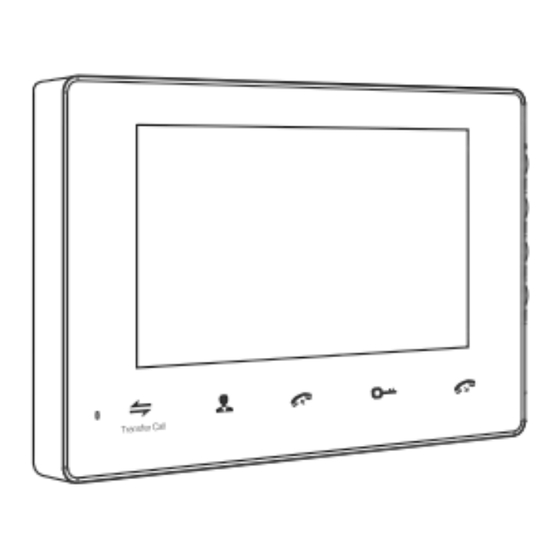
CONTENUTO DEL KIT A. Monitor (YDPI2) Cavetti con Cavetti con 4 2 poli (2) poli (2) Monitor YDPI2(1) Staffa (1) Tasselli (4) Manuale utente (1) Viti (4) Viti (4) Alimentatore switching 15Vdc (1) Alimentatore switching 15Vdc (1) B. Posto esterno... - Page 4 SPECIFICHE A. Monitor (YDPI2) Display LCD 7” Risoluzione 800x480pixel 193mm 12mm Standard PAL/NTSC Fonica Full duplex 123mm Tempo di conversazione 120s Assorbimento stand-by 200 mA max Assorbimento in 500mA max comunicazione Range di temperatura 0-50°C Installazione Parete Memoria interna Sì...
-
Page 5: Installazione
SPECIFICHE A. Posto esterno (YDPE1) 37,03mmm Camera CMOS 1/4”pinhole Risoluzione 600TVL LED IR60 Consumo 200 mA max 126,6mm Alimentazione Alimentato dal monitor interno Temperatura -20+60°C Installazione Parete 57mm Nome 1 Visiera antipioggia 2 Microfono 3 Telecamera 4 LED IR 5 Pulsante di chiamata 6 Altoparlante 7 Slot tasselli 8 Regolazione volume... - Page 6 INTRODUZIONE ALL’UTILIZZO Chiamata visitatore Modalità stand-by Il visitatore preme il pulsante di chiamata Il visitatore preme il pulsante di chiamata del posto esterno 2 del posto esterno 1 Il monitor suona per 10 secondi NOTA L’immagine del visitatore viene visualizzata Durante la conversione tra posto interno e posto esterno 1, se sul monitor viene premuto il pulsante del posto esterno 2 non vi è...
- Page 7 INTRODUZIONE ALL’UTILIZZO Autoaccensione del monitor Modalità stand-by Se nel menu è impostato ON per PORTA2; CAM1; CAM2 è possibile effettuare l’autoaccensione del monitor e vedere in sequenza le immagini della porta1, cam1, porta2, cam2. Monitoring Monitoring Monitoring Monitoring Monitoring ...
-
Page 8: Trasferimento Di Chiamata
INTRODUZIONE ALL’UTILIZZO Trasferimento di chiamata La funzione trasferimento di chiamata richiede almeno 2 postazioni interne e 1 postazione esterna collegate. Durante la conversazione tra posto interno NOTA Quando si effettua il trasferimento di chiamata ad un altro monitor, e posto esterno il primo monitor che ha ricevuto la chiamata si spegne mentre il ... -
Page 9: Menu Setup
INTRODUZIONE ALL’UTILIZZO Menu setup NOTA Il pulsante è un pulsante “multifunzione” che permette di: A: In modalità “standby”, premere il pulsante per entrare nel menu setup. Nella pagine principale del menu setup, scorrere in alto o in basso per selezionare I sotto- menu, premere ancora per entrare nei sotto menu. - Page 10 INTRODUZIONE ALL’UTILIZZO 3. Setup data e info -Data: impostazione data e ora Data e ora 2016-02-05 -Toni tasti: abilitazione o disabilitazione dei toni tasti del monitor Toni tasti -Riavvio: premi , comparirà un pop up con messaggio “Riav- Riavvio via?”, Premi per selezionare “Si”...
-
Page 11: Schemi Di Collegamento
SCHEMI DI COLLEGAMENTO Alimentatori per telecamere scorporate (12Vdc, non inclusi) Alimentatore switching 15Vdc CAM2 CAM1 YDPI2 VIDEO AUDIO INPUT1 VIDEO DATA Alimentazione VIDEO INPUT2 Primo posto MASTER VI/AI/VCC esterno AUDIO Secondo Al prossimo VI/AI/VCC posto esterno monitor DATA VIDEO GND DC 15V/Video/Audio... - Page 12 SCHEMI DI COLLEGAMENTO 1. Schema di collegamento posto esterno 1. Red: DC15 2. Black: GND 3. Brown: COM Serratura elettrica 4. Yellow: NC 5. Blue: NO (non inclusa) Regolazione volume altoparlante 1. Rosso: +15Vdc 2. Nero: GND 3/4. Marrone/Giallo - COM/NC: alla serratura elettrica 3/5.
- Page 13 Install the equipment by carefully following the instructions given by the manufacturer and in compliance with the standards in force. Comelit Group S.p.A declines any responsibility for improper use of the apparatus, for any alterations made by others for any reason, or for the use of non-original accessories or materials.
-
Page 14: The Kit Includes
THE KIT INCLUDES: A. Internal Monitor (YDPI2) Cables 2Pin Cables 4Pin line (2) line (2) Internal Monitor YDPI2 (1) Bracket (1) Screw anchors (4) User manual (1) Wall screws (4) Wall screws (4) External switching power supply 15Vdc (1) External switching power supply 15Vdc (1) B. -
Page 15: Specifications
SPECIFICATIONS A. Internal Monitor (YDPI2) Display screen 7” LCD screen Resolution 800x480pixel 193mm 12mm Standard PAL/NTSC Calling mode Full duplex 123mm Calling time 120s Stand-by absorption 200 mA max Work absorption 500mA max Work temperature 0-50°C Installation Surface mounting Internal storage... -
Page 16: Installation
SPECIFICATIONS A. Outdoor doorbell (YDPE1) 37,03mmm Camera CMOS 1/4”pinhole View angle 600TVL LEDs LED IR60 Stand-by absorption 200 mA max 126,6mm Power supply Supplied from indoor monitor Work temperature -20+60°C Installation Surface mounting 57mm Name 1 Waterproof cover 2 Microphone 3 Camera IR LEDs 5 Call button... -
Page 17: Operation Introduction
OPERATION INTRODUCTION Visitor call Stand-by mode The Visitor presses the call button on The Visitor presses the call button on outdoor camera 2. outdoor camera 1. A 10s of continuous Ding Dong is heard inside and outside NOTICE The visitor’s image automatically displayed During the conversation between internal monitor and outdoor on the screen. - Page 18 OPERATION INTRODUCTION Monitoring Stand-by mode Option in the settings in the menu: CAM1; DOOR2; CAM2 operating mode. Monitoring Monitoring Monitoring Monitoring Monitoring Stand-by DOOR 1 CAM 1 DOOR 2 CAM 2 Show DOOR 1 Show CAM 1 image Close LCD Show DOOR 2 Show CAM 2 image...
- Page 19 OPERATION INTRODUCTION Transfer to other extensions Internal communication function requires at least two indoor and one outdoor units to be connected. Outdoor camera call indoor monitor and NOTICE When you activate the call transfer to another internal monitor, conversation is underway. the first monitor receiving the call will switch off, while second ...
-
Page 20: Menu Operations
OPERATION INTRODUCTION Menu operations NOTICE The button is a three-in-one key, but also composite keys, there are three modes: A: In standby mode, press the button once to enter the main menu settings. In main menu settings, scroll the button upward or downward to select sub-menu, then press again to enter sub-menu. -
Page 21: Set Date And Time
OPERATION INTRODUCTION 3. Set date and time -Time: system date time Time 2016-02-05 -Key tone: Enable or disable the key tone of the indoor monitor. Key Tone -Reboot: press , it will pop-up a window “Reboot?”, scroll Reboot upwards or downwards to select “Yes” or “No”, choose “Yes” to restart the machine, choose “NO”... -
Page 22: Wiring Connection
WIRING CONNECTION Power adapter for external cameras (12Vdc, not included) External switching power supply 15Vdc CAM2 CAM1 VIDEO AUDIO INPUT1 VIDEO DATA VIDEO INPUT2 MASTER VI/AI/VCC AUDIO To next extension VI/AI/VCC DATA indoor unit VIDEO (CN1) GND DC 15V/Video/Audio GND DC 15V/Video/Audio YDPE1 YDPE1 External switching power supply... - Page 23 WIRING CONNECTION 1. Wiring diagram for outdoor doorbell 1. Red: DC15 2. Black: GND 3. Brown: COM Serratura elettrica 4. Yellow: NC 5. Blue: NO (non inclusa) Regolazione volume altoparlante 1. RED: 15Vdc 2. Black: GND 3/4. Brown/Yellow - COM/NC: to magnetic lock 3/5.
- Page 24 COMELIT GROUP S.P.A. Via Don Arrigoni 5 - 24020 Rovetta S.Lorenzo - BG - Italy T: +39 0346 750011 Passion.Technology. Design. www.comelitgroup.com...
Need help?
Do you have a question about the YDPI2 and is the answer not in the manual?
Questions and answers