Table of Contents
Advertisement
Quick Links
Advertisement
Table of Contents

Subscribe to Our Youtube Channel
Related Manuals for Shaw Superdew 3


Summary of Contents for Shaw Superdew 3
-
Page 1: Operating Instructions
Superdew 3 Hygrometer Operating Instructions Issue_0114... - Page 2 EC Declaration of Conformity...
-
Page 3: Table Of Contents
15.0 16.0 Guarantee ....................21 17.0 Superdew 3 Specification ................22 Appendix A - Superdew 3 Setup Menu Flow Diagram ........ 23 18.0 19.0 Appendix B - Alarm 1 & 2 Hotkey Flow Diagram ........24 20.0 Appendix C - Units Hotkey Flow Diagram ........... 25 Appendix D - rS485 Protocol .............. -
Page 4: Unpacking Your Shaw Moisture Meters Superdew 3
1.0 Unpacking your Shaw Moisture Meters Superdew 3 Please examine the Superdew 3 package for any damage or mishandling. If any damage is evident please notify the carrier and the Shaw Moisture Meters representative from where this unit was purchased. -
Page 5: General Information
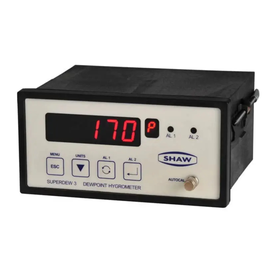
AUTOCAL SUPERDEW 3 DEWPOINT HYGROMETER Every key on the Superdew 3 has two functions, the control function ( & ) and the hotkey function (menu, units, alarm 1 and alarm 2). The use of these commands is described in the following table:... -
Page 6: Safety Information
The Superdew 3 has an AutoCal potentiometer to perform auto calibration of sensors. ● The Superdew 3 has two full range alarms that can be set as rising or falling edge triggered. These alarms have visual indication (LEDs) and activate changeover relays for remote indication or control. -
Page 7: Installation
4.2 Instrument Wiring Wire the Superdew 3 as per figure 1.1 below. Alarm 1 Alarm 2 Power Supply... -
Page 8: Power Supply
4.3 Power Supply The Superdew 3 can be powered by either a 90 - 250 V AC or 24 V DC supply. Connect the required supply cable to the appropriate terminals as shown in figure 1.1. The AC power supply should be between 90 - 250 V AC @ 50/60 Hz. -
Page 9: Installing The Air/Gas Sampling System
5.0 Installing the Air/Gas Sampling System The Piping Installation Schematic diagram (see section 5.1) shows all components that could be used in a dry gas measurement application. Not all the items shown will be required for every installation. Care should be taken to ensure that the sample presented to the measuring sensor is not contaminated with any other component that will damage, contaminate or affect the sensor in a way that will impair the system accuracy. -
Page 10: Piping Installation Schematic
5.1 Piping Installation Schematic MAIN PROCESS LINE Notes a. The sample pipe should be on the upper surface of the horizontal pipe or on a vertical section of pipe wherever possible. b. The sample tube should run continually upwards from the sample point. If this is not possible then an inspection port or drain tap should be installed at the lowest point in the system. -
Page 11: Piping Schematic Component Index
5.2 Piping Schematic Component Index Sample Isolation Valve - This is a recommended item as it allows access to the sample system without interrupting the main process line. Filter Unit – A filter unit is recommended when the samples are likely to contain particulate matter. -
Page 12: Installing And Commissioning The Sensor
6.0 Installing and Commissioning the Sensor It is advisable to carry out an initial purge routine of the sample loop before installing the sensor. This is to remove the possibility of sensor damage on start up. Refer to the Piping Installation Schematic in section 5.1. Open the inlet isolation valve slowly until a small flow of air/gas (at atmospheric pressure) flows through the inlet pipe work to the sensor holder, exhausting through the sensor entry port of the sensor holder. -
Page 13: Default Instrument Configuration
See Appendix A, B & C for flow charts. key allows the user to leave a part of the menu without changing any settings. Wherever a numerical value has to be entered into the Superdew 3 the following text will be found. “Use the &... -
Page 14: Configuring The Superdew 3
Description: The ‘rAngE’ option allows the user to select the required sensor range. This option is used to match the Superdew 3 to the sensor connected to the unit. For example a ‘RED’ sensor requires that the Superdew 3 ‘rAngE’ option ‘rEd’ is selected. -
Page 15: Outpt
9.2 oUtPt Description: The ‘oUtPt’ option of the Superdew 3 allows the user to set the span and the range over which the 4 - 20 mA operates. The default setting is for the output to cover the full operating span of the selected range e.g. -
Page 16: Al1 And Al2
10 second time-out occurs. 9.4 rS485 (Communications) Description: The rS485 option allows the user to set the Superdew 3 address and communication baud rate used when the Superdew 3 is communicating with a PC using rS485 point-... -
Page 17: Pass
‘Addr’, or ‘bAUd’ then press the key. Note: If the key is pressed the Superdew 3 will return to the ‘rS485’ screen. If the ‘Addr’ option is selected the screen will now display the current address value. Use the &... -
Page 18: Normal Operation Of The Superdew 3
10.0 Normal Operation of the Superdew 3 In normal operation, the Superdew 3 will display the current moisture value of the connected sensor. The value is displayed in the currently selected engineering units, which is indicated by the small LED. -
Page 19: Units
If the hotkeys are restricted by the ‘PAnEL’ function then the units can only be reviewed. If the key is pressed to select another moisture unit, the Superdew 3 will display ‘LOC’ and not change the moisture units. Operation To review the Superdew 3 moisture units press the (Units) key for longer than five seconds. -
Page 20: Calibration (Sensor Ranges Up To +20 °C Dewpoint)
Remove the sensor from the sensor holder and expose it to ambient conditions for at least one minute. Compare the reading of the Superdew 3 in the ambient air, against the actual moisture level obtained by another method. Turn the... -
Page 21: Faults/Errors
If the user tries to enter an alarm level above the maximum value of the sensor range selected, the Superdew 3 will display ‘oVEr’. 16.0 Guarantee All Shaw products are guaranteed for two years from the date of purchase, some exclusions are as follows: Removing protective guard from any sensor, subjecting sensor to shock or black list gases e.g. -
Page 22: Superdew 3 Specification
17.0 Superdew 3 Specification Transmitter: Compatible with the Shaw Sensor DIN Style, 144 mm (w) x 72 mm (h) x 116 mm (d) Enclosure: PCB Layout: General PSU PCB and display PCB to fit the DIN enclosure Display: Five characters LED display. Largest positive number... -
Page 23: Appendix A - Superdew 3 Setup Menu Flow Diagram
18.0 Appendix A - Superdew 3 Setup Menu Flow Diagram... -
Page 24: Appendix B - Alarm 1 & 2 Hotkey Flow Diagram
19.0 Appendix B - Alarm 1 & 2 Hotkey Flow Diagram... -
Page 25: Appendix C - Units Hotkey Flow Diagram
20.0 Appendix C - Units Hotkey Flow Diagram... -
Page 26: Appendix D - Rs485 Protocol
A Hart-like protocol is used. A single Superdew 3 may be connected using the universal address of 0. Up to 32 separate Superdew 3 instruments may be connected using address 1 to 32 (NOT including the universal address of 0). - Page 27 Transmit Protocol (as seen by Superdew 3) Byte Description 0, first Preamble Slave-to-Master Return Address 8-bit Arithmetic Or of Address with 128 Command Data Length bits 15 - 8 Status bits 7 - 0 Process Value Single Precision (4-Byte Float)
- Page 28 Example using universal of 0 Poll message sent to Superdew 3 Reply transmitted by Superdew 3 <4 bytes of single float> <1 byte of checksum>...
-
Page 29: Superdew 3 General Assembly Diagram
22.0 Superdew 3 General Assembly Diagram Front View Rear View 116mm Side View 8mm (max) -
Page 30: Sensor Diagram
23.0 Sensor Diagram 143mm 74mm 63mm (7/8”) AF Hex M14 x 1.25mm Pitch 24.0 Sensor Holder Diagram 4 Mounting Holes 5.5 mm ø (0.22 inch ø) 47 mm (1.85 inch) 60 mm (2.36 inch) 34 mm ø (1.34 inch ø) 3 mm (0.125 inch) 46 mm (1.81 inch) 43 mm (1.77 inch) nominal... - Page 31 Shaw Moisture Meters (UK) Ltd. Len Shaw Building Bolton Lane Bradford BD2 1AF England t. +44 (0)1274 733582 f. +44 (0)1274 370151 e. mail@shawmeters.com www.shawmeters.com...
- Page 32 Superdew 3 Operating_Instructions_Issue _0114 © SHAW MOISTURE METERS UK (LTD) 2010 Shaw Moisture Meters (UK) Ltd. Len Shaw Building Bolton Lane Bradford BD2 1AF England t. +44 (0)1274 733582 f. +44 (0)1274 370151 e. mail@shawmeters.com www.shawmeters.com...
Need help?
Do you have a question about the Superdew 3 and is the answer not in the manual?
Questions and answers