
Related Manuals for Kaixin BVT01


Summary of Contents for Kaixin BVT01
- Page 1 KAIXIN BVT01 Bladder Volume Tester User’s Manual Xuzhou Kaixin Electronic Instrument Co., Ltd.
- Page 2 The qualified service personnel who get Kaixin written authorization can repair the instrument out of warranty by themselves. But this should be agreed by Xuzhou Kaixin Electronic Instrument Co., Ltd. We will provide circuit diagrams, component part lists or other information to assist service personnel to repair those parts of our equipment that are designated by our company as repairable by service personnel.
- Page 3 This user’s manual contains warnings for predictable dangers. Users shall also exercise care at any time to be aware of the dangers unforeseen in this manual. Kaixin shall not be liable for the damages and losses arising out of neglecting to follow the operation instructions herein described.
-
Page 4: Safety Cautions
Bladder Volume Tester User’s Manual V1.02 Safety Cautions 1. Warning Symbols and Definitions The following warning symbols are used in this manual to indicate safety level and other important items. Please remember these symbols and understand the meaning as you read this user’s manual. These symbols convey specific meanings as detailed in the table below: Symbols &... -
Page 5: Table Of Contents
Bladder Volume Tester User’s Manual V1.02 Contents Chapter One Overview……………………………………………………………………………1 Chapter Two Technical Specifications……………………………………………………………2 Chapter Three System Outline……………………………………………………………………3 3.1 Structure composition of the instrument……………………………………………………3 3.2 Components name……………………………………………………………………………3 3.3 Parts of the probe………………………………………………………………………..3 3.4 Function keys description…………………………………………………………………..3 Chapter Four System Configuration……………………………………………………………5 Chapter Five Operation Condition………………………………………………………………5 Chapter Six... - Page 6 Bladder Volume Tester User’s Manual V1.02 12.2.1 System cleaning and disinfection…………………………………………………………21 12.2.2 Clean the probe socket……………………………………………………………………23 12.2.3 Clean the touch screen……………………………………………………………………23 12.2.4 Clean the foot switch……………………………………………………………………23 12.2.5 Clean the shell and probe bracket………………………………………………………23 12.2.6 Clean the thermal printer…………………………………………………………………23 12.3 Replace the thermal paper………………………………………………………………24 12.4 Replace the fuse…………………………………………………………………………24 12.5 Use and maintenance for the rechargeable battery………………………………………24 12.6 Replacement of power supply cord………………………………………………………26...
-
Page 7: Chapter One Overview
The expected service life of BVT01 bladder volume tester is 10 years. The applied part is the part between metal ring of probe handle below 5mm and the forefront of the sound head (see Figure 12-1 “Probe regular disinfection”). -
Page 8: Chapter Two Technical Specifications
Bladder Volume Tester User’s Manual V1.02 Chapter Two Technical Specifications 2.1 Technical data 1. Monitor: 5.7” LED 2. Adapter rating: 100-240V~, 1.2-0.6A, 50-60Hz 3. Output of adapter: DC12.8V 3.0A 4. Main device rating: DC12V 3.0A 5. Main Unit Size: approx. 200 * 168 * 165 (mm, L * W * H) 6. -
Page 9: Chapter Three System Outline
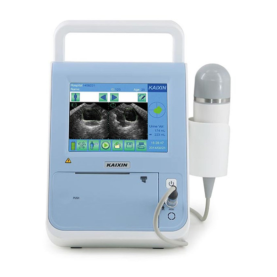
User’s Manual V1.02 Chapter Three System Outline 3.1 Structure composition of the instrument BVT01 bladder volume tester is composed of main unit, probe, etc. 3.2 Components name Fig. BVT01 sketch map 3.3 Parts of the probe Fig. Parts name of 2.5MHz probe... - Page 10 Bladder Volume Tester User’s Manual V1.02 Read data Touch the key to open data file; Save data Touch the key to save data file; Print Print various measurement images/data; Image In main interface, touch the keys to select the selection keys desired left or right image;...
-
Page 11: Chapter Four System Configuration
Bladder Volume Tester User’s Manual V1.02 Chapter Four System Configuration 4.1 Typical configuration 1. Main unit 1 unit 2. 2.5MHz 3D probe 1 pc 3. Power adapter 1 pc 4. Internal battery 1 pc 5. Charger 1 pc 6. Touch pen 2 pcs 4.2 Optional parts 1. -
Page 12: Chapter Six System Installation And Check
Warning: 1. When instrument works abnormally, do stop working, turn off the power and check the reason, then contacts the Kaixin Company about it. 2. Turn off power and pull out of the plug from socket after each operation. 3. It is forbidden to drag and press the power and probe cables emphatically; regularly inspect whether there is spilt and bareness, if there is the phenomena like this, turn off power supply immediately, stop using it and change it for new one. -
Page 13: System Placement
Bladder Volume Tester User’s Manual V1.02 6.1 System placement Please carefully read through and fully understand the safety cautions before moving and placing the system. 1. Unpack the instrument case and check the goods for its completeness according to the packing list furnished. -
Page 14: Install Foot Switch
2. AC/DC adapter is as a part of the equipment, please only use the AC/DC adapter provided by Kaixin Company. 3. To avoid damaging power adapter or harming people by unexpected fallen, make sure the power adapter is placed on the leveled desk. -
Page 15: Use The Touch Screen
Bladder Volume Tester User’s Manual V1.02 6.7 Use the touch screen The touch screen provided with the equipment is a highly sensitive device which enables selections to be made and recorded on screen. On-screen selections should only be made by gently using a finger or the provided touch pen. -
Page 16: Chapter Seven Work Main Interface
Bladder Volume Tester User’s Manual V1.02 Chapter Seven Work Main Interface 7.1 Work main interface Press the button on the front panel, turn on the machine, the touch screen displays the work main interface, as follows: Fig. Work main interface Work main interface shows the ultrasonic images, various parameters and the corresponding operation menus, etc. -
Page 17: Menu Region
Bladder Volume Tester User’s Manual V1.02 The right part displays the bladder projection generated by completed scanning each time, which can be used to locate the position of bladder. The projection position is closer to the center of the coordinate; the measurement results will be more accurate. The machine can simultaneously display two sets of measurements, it is convenient for doctors to compare, “... -
Page 18: Chapter Eight System Preset
Bladder Volume Tester User’s Manual V1.02 Chapter Eight System Preset 』key, the system preset dialog box will be displayed on the screen, as below. Touch『 System Basic Settings About Hospital: Date: 20 14 Y 03 M 12 D YYYY/MM/DD Format: 10 H 28 Min 45 S Time: Min(0-100) - Page 19 Bladder Volume Tester User’s Manual V1.02 4. Touch key on the digital keyboard to complete the entry and the cursor automatically jumps to the next input position; 5. If needs revise, touch key to delete the previous character and retype; Fig.
-
Page 20: Chapter Nine Functional Operation
Bladder Volume Tester User’s Manual V1.02 Chapter Nine Functional Operation 9.1 Startup and Shutdown Press the button on the front panel, turn on the machine. If you want to turn off the machine, please press the button again, then pull out mains plug from the supply mains. 9.2 Input patient information 』key, “Patient Information”... -
Page 21: Save Data
Bladder Volume Tester User’s Manual V1.02 Attention: When copying the data file to U disk, the system time stops until the data store is complete, the system time will automatically return to normal. Copy all files to U disk may take some time, it is recommended that user do not perform other operations. -
Page 22: Thermal Print
Bladder Volume Tester User’s Manual V1.02 The data file is saved in the “123” (patient ID) folder of U disk, which is saved at 9:34:21 on March 12, 2014. U:\USER\4A12948B.BMP (not enter ID) If not enter patient ID, the data file is saved in the “USER” folder of U disk, which is saved at 9:48:22 on October 12, 2014. -
Page 23: Chapter Ten Bladder Volume Measurement
Bladder Volume Tester User’s Manual V1.02 Chapter Ten Bladder volume measurement 10.1 Scanning and positioning bladder The correct positioning of bladder is the basis of accurate measurement of bladder volume. Bladder is located in the lower abdomen, below the pubic symphysis. Before the examination, apply ultrasound coupling gel on the subject, place the probe in accordance with the position of probe shown in the figure below, note that the direction of scanning key on the probe toward the subject’s head. -
Page 24: Manual Contour
Bladder Volume Tester User’s Manual V1.02 2. Place the probe towards the direction of tailbone, press the scan key on the probe or touch the key on the touch screen to scanning the image; 3. Touch patient mode key to select the desired mode: standard mode , obesity mode child mode Description: Child mode is generally applicable to children for 6-12 years old. - Page 25 Bladder Volume Tester User’s Manual V1.02 Operation steps: 1. In the main interface, touch keys to select the image which has a great error; 2. Directly touch left or right image which have large error to enter manual contour interface; 3.
-
Page 26: Chapter Eleven Principle Of Sound Power
Bladder Volume Tester User’s Manual V1.02 Chapter Eleven Principle of Sound Power 11.1 Biological effect It is generally recognized that ultrasonic diagnosis is safe for human’s health. So far, there has been no report on bodily harm done by ultrasound. Nevertheless it is also believed that not all types of ultrasound are absolutely safe. -
Page 27: Chapter Twelve System Maintenance
1. To prevent possible infection, it is advisable to wear sterilized gloves when cleaning, disinfecting the ultrasonic probe. 2. Kaixin Company will not make any guarantee for the efficacy of disinfector. Please contact the appropriate manufacturer for details. 3. Clean the probe with sterile water to remove the residual chemicals after disinfection, because the residual chemicals may be harmful for humans. - Page 28 Bladder Volume Tester User’s Manual V1.02 Attention: 1. In the process of cleaning and disinfection, avoid probe overheat (exceeding 60℃ ℃ ℃ ℃ ) as it may be deformed or damaged under excessive heat. 2. In the operation of disinfection, please refer to medical institutions disinfection technical specifications.
-
Page 29: Clean The Probe Socket
Bladder Volume Tester User’s Manual V1.02 Prohibit immersion Fig. Probe regular disinfection Attention 1. It is a normal phenomenon that color of the acoustic lens may change and color of the probe label may fade away. The regular disinfection times should be minimized as it may lead to degrade of the probe safety and performance. -
Page 30: Replace The Thermal Paper
1. The fuse is inside the power adapter. Fuse shall be replaced by qualified service personnel who get Kaixin approval. 2. Before replacing the fuse, please contact Kaixin and replace it under the guidance of Kaixin. 3. Before replacing the fuse, you must disconnect the mains supply from the mains supply. - Page 31 Bladder Volume Tester User’s Manual V1.02 Attention: 1. Do not throw the battery into water or be wet, which will lead to the battery leakage, explosion or fire; 2. Do not use or store the battery near the heat source, such as fire or heater, which will lead to the battery leakage, explosion or fire;...
-
Page 32: Replacement Of Power Supply Cord
12.8 Periodic Safety Checks To ensure the system performance and safety, it must be checked after using 1 year. When check the instrument, please consult the International Trade Dept of Kaixin or its dealers, as they need to have professional technology engineers. -
Page 33: Essential Performance Checks
Bladder Volume Tester User’s Manual V1.02 Test the protection earth resistance according to IEC 60601-1: Limit: 0.1 . Test the earth leakage current according to IEC 60601-1: Limit: Normal Condition 500µA, Single Fault Condition: 1000µA. Test the touch current according to IEC 60601-1: Limit: Normal Condition 100µA, Single Fault Condition: 500µA. -
Page 34: Chapter Thirteen Storage And Transportation
Bladder Volume Tester User’s Manual V1.02 Chapter Thirteen Storage and Transportation 1. If the instrument is stored over 3 months, take out the instrument from the packing case, connect it to power supply for 4 hours, and then disconnect the power and place it in the case again following the direction indicated by arrows on the package. -
Page 35: Chapter Sixteen Guidance And Manufacturer's Declaration
Bladder Volume Tester User’s Manual V1.02 Chapter Sixteen Guidance and Manufacturer’s Declaration This product complies with EMC test standard IEC 60601-1-2 Warning: The use of inappropriate accessory will reduce the performance of the product. Attention: 1. The use of the accessory, transducer or cable other than those specified may result in increased emissions or decreased immunity of the system. - Page 36 Bladder Volume Tester User’s Manual V1.02 Table 2 - Guidance and manufacturer’s declaration—electromagnetic immunity The equipment is intended for use in the electromagnetic environment specified below. The customer or the user should assure that they are used in such an environment. Immunity test IEC 60601 test Compliance level...
- Page 37 Bladder Volume Tester User’s Manual V1.02 Table 3 - Guidance and manufacturer’s declaration—electromagnetic immunity The equipment is intended for use in the electromagnetic environment specified below. The customer or the user should assure that they are used in such an environment. IEC 60601 test Compliance Electromagnetic environment -...
- Page 38 Bladder Volume Tester User’s Manual V1.02 Table 4 - Recommended separation distance between portable and mobile RF communications equipment and this equipment This equipment is intended for use in an electromagnetic environment in which radiated RF disturbances are controlled. The customer or the user of the equipment can help prevent electromagnetic interference by maintaining a minimum distance between portable and mobile RF communications equipment (transmitters) and this equipment as recommended below, according to the maximum output power of the communications equipment.
-
Page 39: Appendix A System Block Diagram
Bladder Volume Tester User’s Manual V1.02 Appendix A: System Block Diagram - 33 -... -
Page 40: Appendix B Acoustic Output Data Disclosure
In the acoustic output measurement data, the MI uncertainty is 12%, TI uncertainty is 23%. Manufacturer: Xuzhou Kaixin Electronic Instrument Co.,Ltd. Product Name: Bladder Volume Tester Test Mode: B-Mode Probe Type: 2.5S120M1... - Page 41 KAIXIN ELECTRONIC XUZHOU KAIXIN ELECTRONIC INSTRUMENT CO., LTD. Kaixin Mansion, C-01. Economic Development Zone, Xuzhou, Jiangsu, China Post Code: 221004 Tel: +86-516-87732932/87733758 Fax: +86-516-87732932/87792848 Website: http://www.kxele.com E-mail: info@kxele.com Shanghai International Holding Corp. GmbH (Europe) Eiffestrasse 80, 20537 Hamburg, Germany Information contained in this manual is subject to change without further notice.
Need help?
Do you have a question about the BVT01 and is the answer not in the manual?
Questions and answers