Table of Contents
Advertisement
Quick Links
Advertisement
Table of Contents

Subscribe to Our Youtube Channel
Related Manuals for Flomotion Systems be6000 series


Summary of Contents for Flomotion Systems be6000 series
- Page 1 BE6000 Series Ultrasonic Flow Meter...
- Page 2 BE6000 Ultrasonic Flow Meter O&M Manual Flomotion Systems, Inc. ~ FlomotionSystems.com...
- Page 3 BE6000 Ultrasonic Flow Meter O&M Manual Installation and Operation Manual BE6000 Series Ultrasonic Transit-Time Flow Meter July 2007 Flomotion Systems, Inc. 586 N. French Rd. Amherst, NY 14228 U.S.A. 716-691-3941 800-909-3569 www.FlomotionSystems.com Flomotion Systems, Inc. ~ FlomotionSystems.com...
-
Page 4: Table Of Contents
III. Display Windows ____________________________________________________________17 1. Summary ________________________________________________________________________17 2. Descriptions ______________________________________________________________________18 (1) Flow/Totalizer Displays __________________________________________________________________ 18 (2) Initial Setup ___________________________________________________________________________ 20 III. Trouble Shooting ____________________________________________________________39 Power-On self-test information, Causes and Solutions _____________________________________39 Error Code Causes and Solutions ______________________________________________________40 Flomotion Systems, Inc. ~ FlomotionSystems.com... - Page 5 Appendix 2. Sound Velocity and Viscosity of Liquids __________________________________42 Appendix 3. Sound Velocity for Various Common Materials ___________________________43 Pipe Material _______________________________________________________________________43 Liner Material ______________________________________________________________________43 Appendix 4. Sound Velocity in Water (1 ATM) at different temperatures___________________44 Appendix 5. Pipe Dimensions and Weights___________________________________________45 Flomotion Systems, Inc. ~ FlomotionSystems.com...
-
Page 6: Introduction
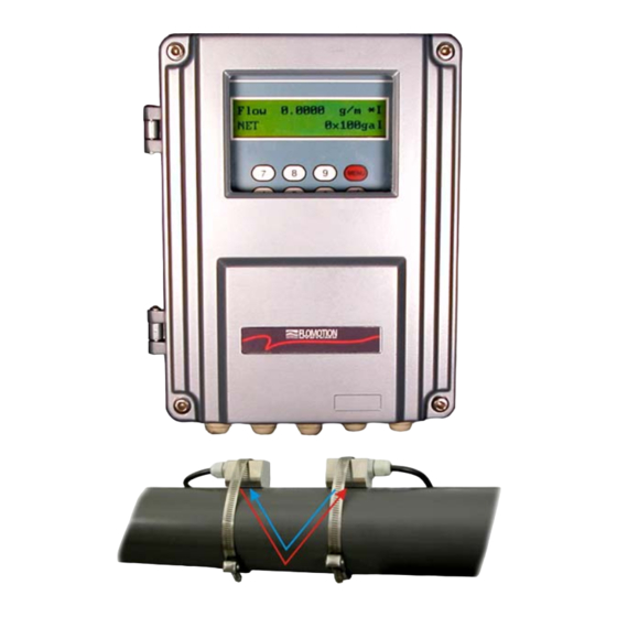
BE6000 Ultrasonic Flow Meter O&M Manual I. Introduction 1. Preface Welcome to BE6000 series ultrasonic flow meter. Please read this instruction manual thoroughly before installation and operation. BE6000 ultrasonic flow meter is a time-difference type ultrasonic flow meter, whose transducers are mounted clamped on pipe. -
Page 7: Operation Principle
With the use of the zero setting function, the meter renders 0.5% accuracy. Flomotion Systems, Inc. ~ FlomotionSystems.com... -
Page 8: Typical Applications
HVAC • Etc. 5. Packing List Items included are as follows; • 1 processor • 1 set of transducers(2 ea) • 1 transducer mounting chain • 1 couplant • 1 instruction manual • Test certificate Flomotion Systems, Inc. ~ FlomotionSystems.com... -
Page 9: Technical Specifications
The meter can use standard 120VAC or 24VDC power supply. By default, the meter is provided with the standard 120VAC power type. Therefore, should the user want 24VDC model, such should be indicated when ordering. Flomotion Systems, Inc. ~ FlomotionSystems.com... -
Page 10: Cables
Cables should never be spliced or cut. Please use the following cables; (1) Power Cable 3-core or 2-core rubber insulated cable (outer diameter 11mm) (2) Output Signal Cable 2-core or many-core rubber insulated cable (11mm) (3) Cable between transducer and processor Flomotion Systems, Inc. ~ FlomotionSystems.com... -
Page 11: Wire Connections
BE6000 Ultrasonic Flow Meter O&M Manual 9. Wire Connections (1) Wall Mount Flomotion Systems, Inc. ~ FlomotionSystems.com... -
Page 12: Installation And Operation
When the above parameters are properly set, the correct transducer mounting distance is calculated and displayed in menu M25. Then the machine searches for proper amplifier gain. After S1, S2, S3 and S4 steps, the machine enters into the normal operation state. Flomotion Systems, Inc. ~ FlomotionSystems.com... -
Page 13: Rapid Setup Procedure
M13, which is the window for inputting the inner diameter of the pipe, press [MENU] [1] [3] [ENT]. 5. Transducer Mounting Distance The distance is measured between the front edges of both transducers. After all the parameters have been set, the distance is shown in M25. Flomotion Systems, Inc. ~ FlomotionSystems.com... -
Page 14: Transducer Mounting Methods
The user can verify whether the mounting is done correctly or not by checking the received signal strength, total travel time, time difference and rate of travel time, which are described below; Flomotion Systems, Inc. ~ FlomotionSystems.com... -
Page 15: Signal Strength & Quality (M90)
(3) Time Rate (TOM/TOS* 100, M91) This is used to confirm whether the transducers are located with the correct interval. This should indicate 100 ±3%. Flomotion Systems, Inc. ~ FlomotionSystems.com... -
Page 16: Selecting A Location For Transducer Mounting
It cures at room temperature upon exposure to moisture in the air. During the cure, it releases acetic acid Apply 1/4” bead of couplant (a vinegar like odor). It reaches full cure within 24 hours. to emitting surface. Flomotion Systems, Inc. ~ FlomotionSystems.com... -
Page 17: Display Windows
+ 8 Receive Shape 30 Measurement Unit in 69 High FO Flow Rate 31 Flow Rate Unit 70 LCD Backlight Option 32 Totalizer Unit 71 LCD Contrast 33 Totalizer Multiplier 72 Working Timer 34 NET Totalizer Flomotion Systems, Inc. ~ FlomotionSystems.com... -
Page 18: Descriptions
(M36), the value shown in the window is replaced by the NEG totalizer last time. • Date and Time/Flow Rate(M04) 05-10-20 10:10 *R Flow 10.023 m This window is for displaying current date, time and flow rate. The time and date can be entered in M60. Flomotion Systems, Inc. ~ FlomotionSystems.com... - Page 19 It shows the status of operation and corresponding status (or error) code. There are several error codes, whose implications and solutions are discussed in “ERROR SEARCHING”. • Net Flow Today(M09) Net Flow of Today 358.34m This window displays the net totalizer of the day. Flomotion Systems, Inc. ~ FlomotionSystems.com...
-
Page 20: Initial Setup
You can select one of the following materials from the list provided; 0. Carbon Steel 5. PVC 1. Stainless Steel 6. Aluminum 2. Cast Iron 7. Asbestos 3. Ductile Iron 8. Fiber Glass- Epoxy 4. Copper 9. Other Flomotion Systems, Inc. ~ FlomotionSystems.com... - Page 21 Liner Thickness 10mm Only when a liner is selected in M16, this menu will be activated. • Inside ABS Thickness(M19) Inside ABS Thickness Input ABS roughness coefficient. Not used. Reserved for future use. • Fluid(M20) Flomotion Systems, Inc. ~ FlomotionSystems.com...
- Page 22 If you select ‘3. User’s Own Type, you should enter a group of transducer parameters such as sound wedge angle, sound wedge velocity, ultrasonic delay and distance between the edge of the transducer and sound. • Transducer Mounting Method(M24) Transducer Mounting 0. V Flomotion Systems, Inc. ~ FlomotionSystems.com...
- Page 23 This value is used to solve the problem of the empty pipe. Even when the pipe is empty, the flow meter will show “Normal Working” for the signals that are transmitted and reflected through the pipe wall. In order to Flomotion Systems, Inc. ~ FlomotionSystems.com...
- Page 24 The totalizer multiplier acts as the function to increase the totalizer indicating range. Meanwhile, the totalizer multiplier can be applied to the positive totalizer, negative totalizer and net totalizer at the same time. The followings options are available; 0. X 0.001 (1E-3) 4. X10 Flomotion Systems, Inc. ~ FlomotionSystems.com...
- Page 25 After “YES” is selected, the following operations are available; None If it is necessary to recover the factory default, press keys after the above-mentioned characters are [.][ ] displayed on the screen. • Manual Totalizer(M38) Flomotion Systems, Inc. ~ FlomotionSystems.com...
- Page 26 “0”. If so, it can be recovered via M43. • Reset Zero(M43) Reset Zero [43 Select “YES”; reset “Zero Point” which was set by the user. • Manual Zero Point(M44) Flomotion Systems, Inc. ~ FlomotionSystems.com...
- Page 27 Keypad Lock Code (M48) Low Flow Cutoff Val. 0.01 m/s The Keypad Lock function is used to avoid any operation errors by unauthorized personnel. (Please contact us if the password is forgotten) • Logger Option (M50) Flomotion Systems, Inc. ~ FlomotionSystems.com...
- Page 28 AI Value Range [54 10-100 To input scale range of temperature, pressure or level for the analog input of 4-20mA. For example, the value 10 in the above box represents 4mA and 100 20mA. • Current Output Selection(M55) Flomotion Systems, Inc. ~ FlomotionSystems.com...
- Page 29 Display CL current output. The display of 10.0000mA indicates that CL current output value is 10.0000mA. If the difference between displaying value and CL output value is too large, the current loop then needs to be re-calibrated accordingly. Flomotion Systems, Inc. ~ FlomotionSystems.com...
- Page 30 Displays the electronic serial number (ESN) of the instrument. This ESN is the only one assigned to each BE6000 series flow meter ready to leave the factory. The factory uses it for files setup and for management by the user.
- Page 31 This option is provided for power saving. • LCD Contrast Controller (M71) LCD Contrast [71 To control the LCD contrast. Press ENT and adjust the number using up or down keys, and press ENT again to confirm. • Working Timer (M72) Flomotion Systems, Inc. ~ FlomotionSystems.com...
- Page 32 15. Key Stroking On The following sources can be selected to set off the buzzer; 0. No Signal 9. POS into Pulse 1. Poor Signal 10. NEG into Pulse 2. Not Ready(No*R) 11. NET into Pulse Flomotion Systems, Inc. ~ FlomotionSystems.com...
- Page 33 Select the batch control type. Available options are as follows; 0. Key Input 4. AI2 Down Edge 1. AI1 Up Edge 5. AI3 Up Edge 2. AI1 Down Edge 6. AI3 Down Edge 3. AI2 Up Edge 7. AI4 Up Edge Flomotion Systems, Inc. ~ FlomotionSystems.com...
- Page 34 Select “No” to cancel this function. • Energy Unit Selection (M84) Energy Unit Select [84 0. Giga Joule(GJ) Select GJ or K.C as energy unit. The default is GJ. • Energy Temperature Source Selection (M85) Flomotion Systems, Inc. ~ FlomotionSystems.com...
- Page 35 Display the measured signal strength and signal quality Q value upstream and downstream. Signal strength is indicated from 00.0~99.9. A reading of 00.0 indicates no signal detected, while 99.9 indicates maximum signal strength. Normally the signal strength should be > 60.0. Signal Quality Q is indicated 00~99. Flomotion Systems, Inc. ~ FlomotionSystems.com...
- Page 36 Normally this scaling factor is the average of line and surface velocity factor inside the pipe. • Print Commands (M97, M98, M99, M9.) Press [MENU] [9] [7]. Prints the following working parameters as set by the user at the initial set up; - Outer Diameter - Wall Thickness Flomotion Systems, Inc. ~ FlomotionSystems.com...
- Page 37 Last Power Off Time 04-07-12 10:12:02 Display the last power off time. • Last Flow Rate [MENU] + 3 Last Flow Rate [+3 100.43 m3/h Displays the last flow rate. • Calculator [MENU] + 5 Flomotion Systems, Inc. ~ FlomotionSystems.com...
- Page 38 Select one of two different communications protocols. • Receive Wave Shape [MENU] + 8 Receive Shape To display the wave shape of ultrasonic signals received by the flow meter. In normal conditions, the displayed wave shape should be constant without fluctuations. Flomotion Systems, Inc. ~ FlomotionSystems.com...
-
Page 39: Trouble Shooting
Soft Reset. Check whether the cables Mis-operation, poor cable contact on response from screen, no on the panel are contacted well. the panel display or disorderly display PRN Time Over Printer wrong or wrong connection. Examine printer or cable. Flomotion Systems, Inc. ~ FlomotionSystems.com... -
Page 40: Error Code Causes And Solutions
The reasons may include all the above- mentioned causes. Empty pipe, M29 menu settings If there is liquid in the pipe, No liquid in the pipe or wrong input “0” in the M29 menu. settings Flomotion Systems, Inc. ~ FlomotionSystems.com... -
Page 41: Appendix 1. Rs-232 Command Protocol
Binary value of A1 input DS(CR) A0 output in percentage AI1(CR) Value of A1 input DC(CR) Current Error Code AI2(CR) Value of A2 input DA(CR) OCT or RELAY alarms Electronic Serial Number DT(CR) Current date and time Flomotion Systems, Inc. ~ FlomotionSystems.com... -
Page 42: Appendix 2. Sound Velocity And Viscosity Of Liquids
0.69 Water 225 1249 0.14 Tetra chloromethane Acetone 1190 Petroleum 1290 Carbinol 1121 Pine oil 1280 Ethanol 1168 Cloroethylene 1050 0.82 Alcohol 1440 Ketone 1310 Acetaldehyde 1180 Glycol 1620 Arachis oil 1472 Castor oil 1502 Flomotion Systems, Inc. ~ FlomotionSystems.com... -
Page 43: Appendix 3. Sound Velocity For Various Common Materials
Fiber, Glass-Epoxy 3430 Glass 3276 Polyethylene 1950 2540 PTFE 1450 Rubber 1600 Liner Material Liner Material Sound Velocity(m/s) PTFE 1225 Titanium 3150 Cement 4190 Bitumen 2540 Porcelain Enamel 2540 Glass 5970 Plastic 2280 Polyethylene 1600 Flomotion Systems, Inc. ~ FlomotionSystems.com... -
Page 44: Appendix 4. Sound Velocity In Water (1 Atm) At Different Temperatures
(m/s) where, "t" is water temperature ( Calculation of Sound Velocity (C ) in Sea Water: +1.39S where, “C “ is the sound velocity in fresh water, “S” is the salinity of the sea water (%) Flomotion Systems, Inc. ~ FlomotionSystems.com... -
Page 45: Appendix 5. Pipe Dimensions And Weights
0.719 9.312 0.216 3.068 0.844 9.062 0.300 2.900 1.000 8.750 0.438 2.624 1.125 8.500 0.600 2.300 11.750 0.375 11.000 4.000 0.083 3.834 3-1/2 0.500 10.750 0.120 3.760 0.875 10.000 0.226 3.548 0.318 3.364 0.636 2.728 Flomotion Systems, Inc. ~ FlomotionSystems.com... - Page 46 14.876 0.625 40.750 1.781 14.438 0.750 40.500 20.000 0.218 19.564 48.000 0.375 47.250 0.250 19.500 0.500 47.000 0.375 19.250 0.500 19.000 0.594 18.812 0.812 18.376 1.031 17.938 1.281 17.438 1.500 17.000 1.750 16.500 1.969 16.062 Flomotion Systems, Inc. ~ FlomotionSystems.com...
- Page 47 42.02 50.50 47.98 50.80 47.96 51.40 47.96 51.98 48.00 56.66 53.96 57.10 54.00 57.80 54.00 58.40 53.94 62.80 60.02 63.40 60.06 64.20 60.20 64.82 60.06 75.34 72.10 76.00 72.10 76.88 72.10 87.54 84.10 88.54 84.10 Flomotion Systems, Inc. ~ FlomotionSystems.com...
Need help?
Do you have a question about the be6000 series and is the answer not in the manual?
Questions and answers