Table of Contents
Advertisement
Quick Links
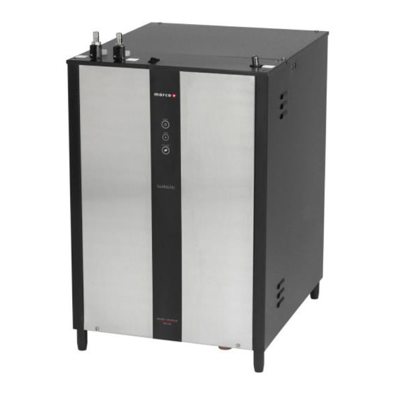
SERVICE MANUAL
Under Counter Range, Model UC45
• 1000743 (2.8kW)
• 1000744 (5.6kW)
• 1000744US (5.6kW)
• 1000745 (8.4kW)
• 1000753 (2.8kW)
• 1000754 (5.6kW)
• 1000755 (8.4kW)
• 1000743A (2.8kW)
• 1000744A (5.6kW)
• 1000745A (8.4kW)
• 1000753A (2.8kW)
• 1000754A (5.6kW)
• 1000755A (8.4kW)
Marco Beverage Systems Ltd.
Ireland Tel:
(01) 295 2674
63d Heather Road,
Ireland Fax:
(01) 295 3715
Sandyford Industrial Estate,
UK Tel:
(0207) 274 4577
Dublin 18,
UK Fax:
(0207) 978 8141
Republic of Ireland
Advertisement
Table of Contents

Related Manuals for Marco Beverage Systems Ecoboiler UC45 1000743

Summary of Contents for Marco Beverage Systems Ecoboiler UC45 1000743
- Page 1 • 1000755 (8.4kW) • 1000743A (2.8kW) • 1000744A (5.6kW) • 1000745A (8.4kW) • 1000753A (2.8kW) • 1000754A (5.6kW) • 1000755A (8.4kW) Marco Beverage Systems Ltd. Ireland Tel: (01) 295 2674 63d Heather Road, Ireland Fax: (01) 295 3715 Sandyford Industrial Estate,...
-
Page 2: Safety Instructions
1. INTRODUCTION: The information provided in this manual is intended to assist in the installation and maintenance of the Marco Ecoboiler Water boiler. Please read the instructions carefully to prevent accidents and ensure an efficient installation. This manual is not a substitute for any safety instructions or technical data affixed to the machine or its packaging. -
Page 3: Basic Instructions
3. BASIC INSTRUCTIONS: 3.1. INSTALLATION DET AILS: Installation details: Power Supply: • 1000744, 1000744US, 1000744A, 1000754, 1000754A (5.6kW/230V, 6.1kW/240V) - This needs to be connected to a 30A isolator outlet. • 1000743, 1000743A, 1000753, 1000753A(2.8kW, 230V) – connected via a 13A plug. •... -
Page 4: Operation
3.2. OPER ATION: • Check that all installation procedures have been carried out. • Ensure water valve is open. • Connect the machine to the mains power and switch the rocker switch on the top of the machine into the ON position. Ecoboiler : Status The Tri-colour LED on the front of the... -
Page 5: Temperature Calibration
3.3. TEM PERATURE CALIBR ATION 3.3.1 Eco Boiler version The Ecoboiler control PCB (1600345) has the ability to have the desired set-point temperature at whatever setting is required. During manufacture of the PCB it is set to the default temperature of around 90°C. - Page 6 • Do the same action with the other font if needed. If only one font is calibrated, settings for the other will not be altered. • The minimum time possible for the time dispense operation is 1s. Setting the dispense time for less (quick font button click) will set the font back into "push &...
-
Page 7: Troubleshooting
3.5. TROUBLESHOOTING The Ready/Status light signals various errors or problems. A cycle of red flashes indicates an error. The number of flashes in a cycle corresponds to the symptom in the table below: Status/Diagnostic light guide: No of Symptom Action required flashes Water level below elements. - Page 8 3 FLASH CYCLE – THERMISTOR OPEN CIRCUIT • Display pattern: 3 flashes then a short pause - repeated. • Electronic check This indicates that the Thermistor is measuring such a large resistance and action: that it assumes the thermistor circuit is open. •...
-
Page 9: Maintenance
6 FLASH CYCLE – NOT FILLING • 6 flashes then a short pause - repeated. Display pattern: • This checks that the water in the tank cools when the inlet solenoid Electronic check and action: valve is switched on. • This is a recoverable error. This checks that the water in the tank is cooled by when the inlet solenoid valve is opened. -
Page 10: Cautions And S Afety Tips
3.9. CAUTIONS AND S AFETY TIPS: • This appliance must be earthed. If the moulded plug supplied is not used then ensure that the green/yellow cable is connected to a suitable earth. • Risk of flooding. The hose supplied with this unit is non-toxic food quality tested to 190psi. However, a hose is not a permanent connection. -
Page 11: External Arr An Gem Ent
4.2. EXTERNAL ARR AN GEM ENT FONTS MAY VARY Depending on font the type the drip tray will either have to be manually emptied Connected to a drain via drip tray outlet. 2- wire Electrical Connection Font to Boiler Font Water Connection. - Page 12 Connections 1000744US: Figure shows the typical connection method for connecting font(s) to a US under counter boiler. Refer to the Font instructions which accompanied the Font unit for more details. Fonts will vary. Depending on font the type the drip tray will either have to be manually emptied Connected to a drain via drip tray outlet.
- Page 13 4.3. ACCESS TO INTERNAL COM PONENTS: To access the tank: Allow to cool. Remove the rear outer lid. To remove rear outer lid, undo 4 flat headed screws. Ensure that the tank is cool, before removing insulation and inner lid. To remove inner lid, undo 4 butterfly nuts.
- Page 14 Service manual April 2017 Ecoboiler UC45 Page 14 of 28...
-
Page 15: Internal Arr An Gem Ent
4.4. INTERNAL ARR AN GEM ENT: Service manual April 2017 Ecoboiler UC45 Page 15 of 28... - Page 16 4.5. PCBs: 4.5.1. PCB Layout: Ecoboiler : PCB Ecoboiler Control (1600345): • Controls the heater switching • Controls the water inlet switching • Controls tank temperature/temperature adjustment Ecosmart: PCB Eco Slave (1600354): • Controls the heater switching • Controls the water inlet switching •...
- Page 17 4.5.2. PCB Ecoboiler Control: PCB Ecoboiler Control (1600345) / PCB Eco Slave (1600354): Item Description: Dispense Solenoid / Pump Tab Inlet Solenoid Tab Neutral Tabs Transformer Mains Live In Tab Relays - Heater. Switch the element Heater Tab On/Off 2-way Connector. Short circuited on this Ecoboiler. LED 5-way Connector Earth Tab Daughter PCB Connector (low voltage).
- Page 18 4.5.2. PCB PUM P TIM ER: PCB Pump timer (1600358) : Item Description: Pump drive Tab Pump drive Tab Neutral Tabs Transformer Mains Live In Tab Relays - Heater. Heater Tab On/Off 2-way Connector. Short circuited on this Ecoboiler machines LED 5-way Connector Earth Tab Daughter PCB Connector (low voltage).
-
Page 19: Troubleshooting - Diagnostic Guide
4.5.3. PCB ECOSM ART Display (1600357) Item Description: Power On LED’s. Shows that machine is switched on Power On/Off switch Status LED’s. Displays Error signals via a flashing RED LED Eco Mode LED’s Eco Mode On/Off Switch 2 way connector – to Font connector 16 way connector –... - Page 20 4.7. Tank Components The tank internals are detailed below. Item no: Part number: DESCRIPTION: Probe Assembly – High position 2300463 Probe Assembly – Low position 2300463 Thermistor Pocket – ensure that this is not touching the element. 1500985 Element 2.8kW 230V (Butterfly) 1800306 Gasket Inner Ecoboiler Care should be taken when cleaning inside the tank.
- Page 21 4.9. Wiring diagram: 1000743 1000743A Service manual April 2017 Ecoboiler UC45 Page 21 of 28...
- Page 22 4.10. Wiring Diagrams: 1000744 1000744A 1000744US Service manual April 2017 Ecoboiler UC45 Page 22 of 28...
- Page 23 4.11. Wiring Diagram : 1000745 1000745A Service manual April 2017 Ecoboiler UC45 Page 23 of 28...
- Page 24 4.12. Wiring Diagram : 1000753 1000753A Service manual April 2017 Ecoboiler UC45 Page 24 of 28...
- Page 25 4.12. Wiring Diagram : 1000754 1000754A Service manual April 2017 Ecoboiler UC45 Page 25 of 28...
- Page 26 4.12. Wiring Diagram : 1000755 1000755A Service manual April 2017 Ecoboiler UC45 Page 26 of 28...
- Page 27 4.13. Spare Parts List Service manual April 2017 Ecoboiler UC45 Page 27 of 28...
- Page 28 Part Description Model Variant Number 1000743/A 1000744/A 1000745/A 1000753/A 1000754/A 1000755/A 1000744US (2.8kW) (5.6kW) (8.4kW) (2.8kW) (5.6kW) (8.4kW) (5.6kw) 1500985 Element 2.8kW 230V 1501430 Moulded Plug and cord 1501484 Plug Molded NEMA L6-30P 1501542 Pump Muller 24V DC 1502075 Thermal Switch Dual Pole 125Deg Valve Inlet...
Need help?
Do you have a question about the Ecoboiler UC45 1000743 and is the answer not in the manual?
Questions and answers