Table of Contents
Advertisement
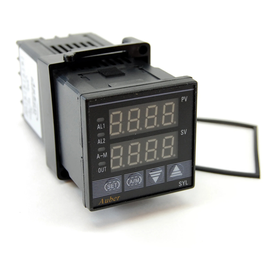
AUBER INSTRUMENTS
Instruction Manual
SYL-2342, SYL-2352 PID TEMPERATURE CONTROLLER
Caution
This controller is intended to control equipment under normal operating
conditions. If failure or malfunction of the controller may lead to abnormal
operating conditions that may result in personal injury or damage to the
equipment or other property, devices (limit or safety controls) or systems
(alarm or supervisory) intended to warn of or protect against failure or
malfunction of the controller must be incorporated into and maintained as
part of the control system.
Installing the rubber gasket supplied will protect the controller front panel
from dust and water splash (IP54 rating). Additional protection is needed
for higher IP rating.
This controller carries a 90-day warranty. This warranty is limited to the
controller only.
1. Specification
Thermocouple(TC): K, E, S, N, J, T, B, WRe5/26
RTD(Resistance temperature detector): Pt100, Cu50
DC Voltage: 0~5V, 1~5V, 0~1V,
Input type
-100~100mV, -20~20mV, -5~5V, 0.2~1V.
DC current : 0~10mA, 1~20mA, 4~20mA. (use external
shunt resistor for higher current)
Input range
Please see section 4.7 for detail.
±0.2% Full scale: RTD, linear voltage, linear current and
thermocouple input with ice point compensation or Cu50
copper compensation.
0.2% Full scale or ±2 ºC: thermocouple input with internal
Accuracy
automatic compensation.
Note: for thermocouple B, the measurement accuracy of ±
0.2% can only be guaranteed when input range is between
600~1800 ºC.
Response time
≤ 0.5s (when FILt=0)
Display resolution
1 °C, 1 °F; or 0.1 °C
Fuzzy logic enhanced PID control
Control mode
On-off control
Manual control
Relay contact (NO): 250VAC/7A, 120V/10A, 24VDC/10A
Output mode
SSR voltage output: 12VDC/30mA
Alarm output
Relay contact. 250VAC/1A, 120VAC/3A, 24V/3A
Process high alarm, process low alarm, deviation high
Alarm function
alarm, and deviation low alarm
Manual function
Automatic/Manual bumpless transfer
Power supply
85~260VAC/50~60Hz
Power consumption ≤5 Watt
Ambient temperature 0~50ºC, 32~122ºF
Dimension
48 x 48 x100 mm (WxHxD)
Mounting cutout
45 x 45 mm
2011.02
INSTRUCTION MANUAL
Version 4.4
2. Available Configurations
Table 1. Controller models
Model
SYL-2342
SYL-2352
SYL-2342P
SYL-2352P
All the models listed in table 1 are 1/16 DIN size with dual-alarm outputs.
3. Terminal Wiring
Model SYL-2342, SYL-2342P
+
+
RTD
R
mA
V
R
W
3.1 Sensor connection
Please refer to table 3 for the input sensor type (Sn) setting codes. The initial
setting for input is for a K type thermocouple. Set Sn to the right sensor code
if another sensor type is used.
3.1.1 Thermocouple
The thermocouple should be connected to terminals 4 and 5. Make sure that
the polarity is correct. There are two commonly used color codes for the K
type thermocouple. US color code uses yellow (positive) and red (negative).
Imported DIN color code uses red (positive) and green/blue (negative). The
temperature reading will decrease as temperature increases if the connection
is reversed.
When using ungrounded thermocouple that is in touch with a large
conductive subject, the electromagnetic field picked up by the sensor tip
might be too large for the controller to handle, the temperature display will
change erratically. In that case, connecting the shield of thermocouple to
terminal 5 (circuit ground of the controller) might solve the problem. Another
option is to connect the conductive subject to terminal 5.
3.1.2 RTD sensor
For a three-wire RTD with standard DIN color code, the two red wires should
be connected to the terminals 3 and 4. The white wire should be connected
to terminal 5. For a two-wire RTD, the wires should be connected to terminals
4 and 5. Jump a wire between terminals 3 and 4. Set controller input type, Sn
to 21.
3.1.3 Linear input (V or mA)
Voltage and mA current signal inputs should be connected between terminals
2 and 5. Terminal 2 is positive.
3.2 Power to the controller
The power cables should be connected to terminals 9 and 10. Polarity does
not matter. It can be powered by 85- 2 6 0 V A C power source. N e i t h e r a
transformer nor jumper is needed to wire it up. For the sake of consistency
with the wiring example described later, we suggest you connect the hot wire
to terminal 9 and neutral to 10.
WWW.AUBERINS.COM
Control output
Relay contact output
SSR control output
Relay contact output
SSR control output
Model SYL-2352, SYL-2352P
AL1
AL2
1
13 14
6
2
7
Out
+
3
8
mA
V
4
9
AC
85~260V
5
10
TC
Figure 1. Wiring diagram
Ramp/soak option
No
No
Yes
Yes
AL1
AL2
1
13 14
6
+
+
2
7
SSR
RTD
3
8
-
R
4
9
AC
R
85~260V
5
10
W
TC
P1/8
Advertisement
Table of Contents

Related Manuals for Auber SYL-2342

Summary of Contents for Auber SYL-2342
- Page 1 AUBER INSTRUMENTS WWW.AUBERINS.COM Instruction Manual SYL-2342, SYL-2352 PID TEMPERATURE CONTROLLER INSTRUCTION MANUAL Version 4.4 2. Available Configurations Caution This controller is intended to control equipment under normal operating Table 1. Controller models conditions. If failure or malfunction of the controller may lead to abnormal...
- Page 2 5 SSRs in parallel. The relay output of the controller ③ AL1 indicator: It lights up when AL1 relay is on. SYL-2342 can be used to turn on a contactor or a solenoid valve. It can drive ④ AL2 indicator: It lights up when AL2 relay is on.
- Page 3 AUBER INSTRUMENTS WWW.AUBERINS.COM 4.2.2 Display change 4.4 Parameter Setting Press the SET key to change the display mode. The display can be changed Table 2. System parameters between display modes 1 and 2. 4.2.3 Manual/Automatic mode switch Code Description Setting Range...
- Page 4 AUBER INSTRUMENTS WWW.AUBERINS.COM The things you should know about alarm tuning from the front panel is inhibited to prevent accidental re-starting of the 1) Absolute alarm and deviation alarm auto tuning process. To start auto tuning again, set At=1 or At=2.
- Page 5 WWW.AUBERINS.COM AUBER INSTRUMENTS 4.5.3. Manual mode 2) For linear input devices (voltage, current or resistance input, Sn=26-37) Manual mode allows the user to control the output as a percentage of the Table 4. dP parameter setting total heater power. It is like a dial on a stove. The output is independent of the dP Value temperature sensor reading.
- Page 6 120VAC to smooth the input. “FILt” may be configured in the range of 0 to 20. Figure 6. SYL-2342 or SYL-2342P control the heater directly by the Stronger filtering increases the stability of the readout display, but causes internal relay of the controller. The heater must consume less current than more delay in the response to change in temperature.
- Page 7 SYL-2342 Fuse 120VAC Figure 10. SYL-2342 or SYL-2342P with thermocouple input. This is a typical wiring set up for a 24V gas, hot water valve, or a contactor with 24V coil voltage. 5.6 Cooling and heating with the same controller...
- Page 8 AUBER INSTRUMENTS WWW.AUBERINS.COM Quick Guide for SYL-2342, 2352 1. Wiring If the external switching device is not on, then the problem is either the 1) Power to the controller. Connect the 85-260V AC power to terminals 9 and controller output, or the external switch device.
Need help?
Do you have a question about the SYL-2342 and is the answer not in the manual?
Questions and answers