
Subscribe to Our Youtube Channel
Related Manuals for FEIG OBID i-scan

Summary of Contents for FEIG OBID i-scan
- Page 1 MONTAGE ® OBID i-scan INSTALLATION ID ISC.LRU3500 ID ISC.LRU3000 (deutsch / english) preliminary public (B) 2010-03-01 M91001-0ed-ID-E.doc...
- Page 2 ® OBID i-scan Montage ID ISC.LRU3000 deutsche Version ab Seite 3 english version from page 30 FEIG ELECTRONIC GmbH Seite 2 von 52 LRU3000 - Manual.doc...
- Page 3 Hinweise jederzeit dankbar. Die in diesem Dokument gemachten Installationsempfehlungen gehen von günstigsten Rahmenbedingun- gen aus. FEIG ELECTRONIC GmbH übernimmt weder Gewähr für die einwandfreie Funktion in system- fremden Umgebungen, noch für die Funktion eines Gesamtsystems, welches die in diesem Dokument be- schriebenen Geräte enthält.
-
Page 4: Table Of Contents
® OBID i-scan Montage ID ISC.LRU3000 Inhalt Leistungsmerkmale der Readerfamilie ID ISC.LRU3000 Leistungsmerkmale.......................6 Verfügbare Readertypen....................6 Verfügbares Zubehör ....................6 Montage Anschlüsse Antennenanschluss ......................9 3.1.1 Versorgungsspannung über X1..................9 Schnittstellen .......................10 3.2.1 X2 Versorgungsspannung über PoE (Power over Ethernet) an X2 ......10 3.2.2 Ethernet-Schnittstelle an X2 (10/100Tbase)..............11 3.2.3 USB –... - Page 5 ® OBID i-scan Montage ID ISC.LRU3000 Sicherheits- und Warnhinweise - vor Inbetriebnahme unbedingt lesen • Das Gerät darf nur für den vom Hersteller vorgesehenen Zweck verwendet werden. • Beim Aufstellen des Gerätes im Geltungsbereich der FCC 47 CFR Part 15 ist ein Mindestab- stand von 25 cm zwischen Antenne und menschlichem Körper zu gewährleisten.
-
Page 6: Leistungsmerkmale Der Readerfamilie Id Isc.lru3000
® OBID i-scan Montage ID ISC.LRU3000 Leistungsmerkmale der Readerfamilie ID ISC.LRU3500/3000 1.1 Leistungsmerkmale Der Reader ist für das Lesen von passiven Datenträgern, sogenannten „Smart Labels“, mit einer Betriebsfrequenz im UHF Bereich entwickelt. 1.2 Verfügbare Readertypen Folgende Reader sind z.Z. verfügbar:... -
Page 7: Montage
® OBID i-scan Montage ID ISC.LRU3000 Montage Der Reader ist für die Montage auf Wänden, auch im Freien, konzipiert. Zur Wandmontage befin- den sich im Gehäuse vorgesehene Löcher. Ein Aufschrauben des Gehäuses zur Montage ist nicht erforderlich. 68 (2.68) 261,3 (10.29) 241,7 (9.52) -
Page 8: Anschlüsse
® OBID i-scan Montage ID ISC.LRU3000 Anschlüsse An der Unterseite des Gehäuses befinden sich die Kabelanschlüsse. Bild 2: Anschlussübersicht zeigt die Anordnung und in Tabelle 3 Anschlussklemmen ist dargestellt, welche Anschlüsse für die einzelnen Leitungen verwendet werden sollen. In Tabelle 4 sind die verfügbaren Taster aufgelistet. -
Page 9: Antennenanschluss
® OBID i-scan Montage ID ISC.LRU3000 3.1 Antennenanschluss Die SMA-Buchsen für den Anschluss der externen Antennen befindet sich ebenfalls auf der Unter- seite des Readers Das maximale Anzugsdrehmoment der SMA-Buchsen beträgt 0,45 Nm. Achtung: Höhere Anzugsdrehmomente führen zur Zerstörung des Steckers. -
Page 10: Schnittstellen
® OBID i-scan Montage ID ISC.LRU3000 3.2 Schnittstellen 3.2.1 X2 Versorgungsspannung über PoE (Power over Ethernet) an X2 Alternativ kann der Reader über den LAN-Anschluss X2 mit Hilfe eines „Power over Ethernet“- Netzteil gem. IEEE802.3at*, Class4 (30/25,5Watt) versorgt werden. Die DC Speisung kann über die freien Pin’s 4,5 und 7,8 erfolgen (Midspan-Power), als auch eine „Phantomspeisung“... -
Page 11: Ethernet-Schnittstelle An X2 (10/100Tbase)
® OBID i-scan Montage ID ISC.LRU3000 3.2.2 Ethernet-Schnittstelle an X2 (10/100Tbase) Der Reader verfügt über eine integrierte 10/100 base-T Netzwerkschnittstelle mit standard RJ-45- Anschluss. Der Anschluss erfolgt über X2 und hat eine automatische „Crossover Detection“ ent- sprechend dem 1000BASE-T Standard. -
Page 12: Usb - Schnittstelle X3 (Host Kommunikation)
® OBID i-scan Montage ID ISC.LRU3000 3.2.3 USB – Schnittstelle X3 (Host Kommunikation) Der Anschluss der USB-Schnittstelle erfolgt über Buchse X3. Die Belegung ist genormt. Die Daten- rate des Readers ist auf 12 Mbit beschränkt (USB Full Speed). Es kann ein Standard-USB-Kabel verwendet werden. -
Page 13: Rs232-Schnittstelle X6
® OBID i-scan Montage ID ISC.LRU3000 3.2.5 RS232-Schnittstelle X6 Der Anschluss der RS232-Schnittstelle erfolgt über X6. Die Übertragungsparameter können per Softwareprotokoll konfiguriert werden. Bild 8 Anschlussbelegung X6 (RS232-Schnittstelle) Bild 9: Verdrahtungsbeispiel für den Anschluss der RS232-Schnittstelle FEIG ELECTRONIC GmbH Seite 13 von 52... -
Page 14: Rs485-Schnittstelle X6
® OBID i-scan Montage ID ISC.LRU3000 3.2.6 RS485-Schnittstelle X6 Der Anschluss der RS485-Schnittstelle erfolgt ebenfalls über X6. Die Übertragungsparameter können per Softwareprotokoll konfiguriert werden. Bild 10 Anschlussbelegung X6 (RS485-Schnittstelle): Kurzzeichen Beschreibung RS485 – GND RS485 – (A -) RS485 – (B +) Tabelle 9: Pinbelegung RS485-Schnittstelle 3.2.6.1 Adresseinstellung RS485 für Busbetrieb... -
Page 15: Digitale Eingänge X5
® OBID i-scan Montage ID ISC.LRU3000 3.3 Digitale Eingänge X5 Die Optokoppler Eingänge an Klemmleiste X5 sind galvanisch von der Reader-Elektronik getrennt und müssen daher mit einer externen Spannung versorgt werden. Bild 11 Klemmleiste Digitale Eingänge IN1 – IN5 Rint... - Page 16 ® OBID i-scan Montage ID ISC.LRU3000 Externe Spannung U Benötigter externer Vorwiderstand R 5 V ... 10 V 11 V ... 15 V 270 Ω 16 V ... 20 V 560 Ω 820 Ω 21 V ... 24 V Tabelle 10: Benötigter externer Vorwiderstand R Hinweise: •...
-
Page 17: Ausgänge
® OBID i-scan Montage ID ISC.LRU3000 3.4 Ausgänge 3.4.1 Digitale Ausgänge X5 Optokopplerausgang (X5/1-2): Der Transistoranschluss, Kollektor und Emitter, des Optokopplerausgangs ist von der Reader- Elektronik galvanisch getrennt und ohne interne Zusatzbeschaltung an Klemme X5 nach außen geführt. Der Ausgang muss daher mit einer externen Spannung betrieben werden. -
Page 18: Relais X5
® OBID i-scan Montage ID ISC.LRU3000 3.4.2 Relais X5 Es stehen 3 Relaisausgänge an der Anschlussklemme X5 als Schließer zur Verfügung. Bild 15: Pinbelegung Relaisausgänge REL1-3 Hinweise: • Jeder Relaisausgang ist für max. 24 V DC / 2 A Dauerlast ausgelegt. Der maximale Schaltstrom darf 1 A nicht überschreiten. -
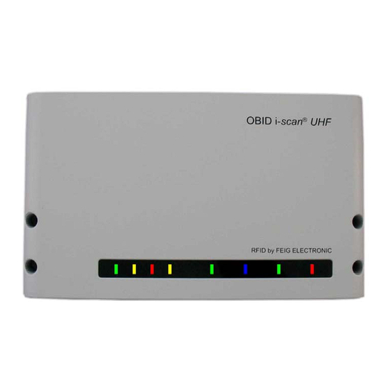
Page 19: Bedien- Und Anzeigeelemente
® OBID i-scan Montage ID ISC.LRU3000 Bedien- und Anzeigeelemente 4.1 Status LEDs Host Warning Kommunikation ANT 1- 4 Input Output Grün Gelb Beschreibung Bootvorgang (ca.10s) nach dem Einschalten BLINKT Normaler Readerbetrieb (ohne Host Kommunikation) BLINKT BLINKT Reader empfängt gültiges Protokoll vom Host... -
Page 20: Reset-Taster
® OBID i-scan Montage ID ISC.LRU3000 Grün Gelb Beschreibung Konfigurations-Reset: BLINKT BLINKT BLINKT Während T1 gedrückt wird bis maximal 5s (Lauflicht) Nachdem T1 für 5s gedrückt wurde, Konfigurations-Reset abgeschlossen. Input / Output LED (gelb): Kann den Status eines Digitalen Ein- oder Ausgangs an- Konfigurierbare Anzeige. -
Page 21: Reader Leistungseinstellung
** Korrekturfaktor zur Umrechnung der abgestrahlten Leistung von e.r.p in e.i.r.p Für die Berechnung der am Reader einzustellenden Sendeleistung steht eine „Calc-RF-Power.xls“ Excel Datei zur Verfügung. Verfügbar bei Feig Electronic GmbH. Beispiel: Tabelle 12: Berechnung der maximalen zulässigen Ausgangsleistung des Readers ** lineare Antenne = „0“, zirkulare Antennen = „1“... -
Page 22: Fcc-Reader
Berechnung der Ausgangsleistung des Readers der Antennengewinn und die Kabeldämpfung mit berücksichtigt werden. Wird eine zirkulare Antenne verwendet, so können 3dB von dem Antenne- gewinn [G]= dBic abgezogen werden. Dies trifft zu bei Verwendung der FEIG Standardantenne ANT.U600/270. Bei solch einer Konstellation ergibt sich folgende Berechnung der Aus- gansgleistung des Readers: = 36 dBm (4 W e.i.r.p) –... - Page 23 ® OBID i-scan Montage ID ISC.LRU3000 Beispiel 2: Antenne ANT.U600/270 mit 6m Belden H155 Koaxialkabel: = 36 dBm – 10,5 dBic + 3 dB + 1,8 dB = 36 dBm – 7,5 dBi + 1,8 dB = 30,3 dBm Reader Configuration = 1,0 Watt Aus Beispiel 2 lässt sich ableiten, dass bei der Verwendung der ANT.U600/270 eine Anpassung...
-
Page 24: Funkzulassungen
® OBID i-scan Montage ID ISC.LRU3000 Funkzulassungen 5.1 Europa (CE) Die Funkanlage entspricht, bei bestimmungsgemäßer Verwendung den grundlegenden Anforde- rungen des Artikels 3 und den übrigen einschlägigen Bestimmungen der R&TTE Richtlinie 1999/5/E6 vom März 99. Equipment Classification gemäß ETSI EN 301 489: Class 2... -
Page 25: Usa (Fcc)
Changes or modifications made to this equipment not expressly approved by FEIG ELECTRONIC GmbH may void the FCC authorization to operate this equipment. NOTE: This equipment has been tested and found to comply with the limits for a Class B digital device, pursuant to Part 15 of the FCC Rules. -
Page 26: Technische Daten
® OBID i-scan Montage ID ISC.LRU3000 Technische Daten Mechanische Daten • Gehäuse Aluminium, pulverbeschichtet • Abmessungen ( B x H x T ) 261,3 x 157,3 x 68 mm³ • 2,0 kg Gewicht • Schutzart IP 53 (mit Schutzkappe IP64) •... - Page 27 ® OBID i-scan Montage ID ISC.LRU3000 Funktionsmerkmale • Protokoll Modi - FEIG ISO Host Mode – Buffer Reader Mode (Data Filtering and - Notification Mode buffering) – Scan Mode • Unterstützte Transponder - EPC class 1 Gen 2 – EM4222 / 4444 (optional) –...
- Page 28 Composition of the information in this manual has been done to the best of our knowledge. FEIG ELECTRONIC GmbH does not guarantee the correctness and completeness of the details given in this manual and may not be held liable for damages ensuing from incorrect or incomplete information.
- Page 29 ® OBID i-scan Installation ID ISC.LRU3000 Contents Performance Features of Reader Family ID ISC.LRU3000 Performance features....................31 Available Reader types ....................31 Available Accessories ....................31 Installation Terminals Antenna connection ....................34 9.1.1 Power supply connection on X1 ..................34 Interfaces ........................35 9.2.1 Power Supply via PoE (Power over Ethernet) on X2 ............35 9.2.2 Ethernet-Interface on X2 (10/100Tbase) ...............36...
- Page 30 ® OBID i-scan Installation ID ISC.LRU3000 Safety Instructions / Warning - Read before start-up ! • The device may only be used for the purpose intended by the manufacturer • When installing the device in areas covered under FCC 47 CFR Part 15 a minimum separation of 25 cm between antenna and the human body must be maintained.
-
Page 31: Performance Features Of Reader Family Id Isc.lru3000
® OBID i-scan Installation ID ISC.LRU3000 Performance Features of Reader Family ID ISC.LRU3000 7.1 Performance features The Reader has been developed for reading passive data carriers, so-called „Smart Labels“, using an operating frequency in the UHF range. 7.2 Available Reader types... -
Page 32: Installation
® OBID i-scan Installation ID ISC.LRU3000 Installation The Reader is designed for wall-mount, including outdoors. Holes for mounting on a wall are provided in the housing. It is not necessary to open the reader housing. 68 (2.68) 261,3 (10.29) 241,7 (9.52) Fig. -
Page 33: Terminals
® OBID i-scan Installation ID ISC.LRU3000 Terminals On the lower side of the reader housing the different cable connectors are positioned. Fig. 2 shows the arrangement of the connectors and Table 3s shows which connection for the different cables are used for. -
Page 34: Antenna Connection
® OBID i-scan Installation ID ISC.LRU3000 9.1 Antenna connection The external SMA antenna connectors are positioned on the lower side of the reader. The maximum tightening torque for the SMA sockets is 0.45 Nm (4.0 lbf in). Caution: Exceeding the tightening torque will destroy the plug. -
Page 35: Interfaces
® OBID i-scan Installation ID ISC.LRU3000 9.2 Interfaces 9.2.1 Power Supply via PoE (Power over Ethernet) on X2 Optional the reader can be powered via the LAN connector on X2 with the use of a PoE „Power over Ethernet“ power supply according to IEEE802.3at*, Class4 (30/25,5Watt). The DC supply can be achieved via the free pin’s 4,5 and 7,8 (Midspan-Power). -
Page 36: Ethernet-Interface On X2 (10/100Tbase)
® OBID i-scan Installation ID ISC.LRU3000 9.2.2 Ethernet-Interface on X2 (10/100Tbase) The Reader has an integrated 10 / 100 base-T network port for an RJ-45. Connection is made on X2 and has an automatic “Crossover Detection” according to the 100BASE-T Standard. -
Page 37: Usb - Interface X3 (Host Communication)
® OBID i-scan Installation ID ISC.LRU3000 9.2.3 USB – Interface X3 (Host Communication) The USB socket on the board is terminal X3. The pinout is standardized. The data rate is reduced to 12 Mbit (USB full speed). A standard USB-cable can be used. -
Page 38: Rs232-Interface X6
® OBID i-scan Installation ID ISC.LRU3000 9.2.5 RS232-Interface X6 The RS232 interface is connected on X6. The transmission parameters can be configured by means of software protocol. Fig. 8 RS232 interface pin-outs on X6 Fig. 9: Wiring example for connecting the RS232 interface RS485-Schnittstelle X6... -
Page 39: Rs485-Interface On X6
® OBID i-scan Installation ID ISC.LRU3000 9.2.6 RS485-Interface on X6 The connection of the RS485 interface take place via the X6 connector as well. The interface parameter can be configured via software protocols. Fig. 10 RS485 interface pin-outs on X6 (RS485-Interface):... -
Page 40: Digital Inputs X5
® OBID i-scan Installation ID ISC.LRU3000 9.3 Digital Inputs X5 The optocouplers on Terminal X5 are galvanically isolated from the Reader electronics and must therefore be externally supplied. Fig. 11 Optocoupler pin-outs IN1 – IN5 Rint Rext Uext IN1..5 Fig. 12 Internal and possible external wiring of the optocouplers Optocoupler input (X5/1-5): The input LED associated with the optocoupler is connected internally to a series resistor of 500 Ω. - Page 41 ® OBID i-scan Installation ID ISC.LRU3000 External voltage U Required external series resistor R 5 V ... 10 V 11 V ... 15 V 270 Ω 16 V ... 20 V 560 Ω 820 Ω 21 V ... 24 V...
-
Page 42: Outputs
® OBID i-scan Installation ID ISC.LRU3000 9.4 Outputs 9.4.1 Digital Outputs X5 Optocoupler output (X5/1-2): The transistor connections, collector and emitter, of the optocoupler output are galvanically isolated from the Reader electronics and are carried to the outside without any internal ancillary circuitry on Terminal X5. -
Page 43: Relays X5
® OBID i-scan Installation ID ISC.LRU3000 9.4.2 Relays X5 There are 3 relay outputs available on connector X5. Fig. 15: Relay output pin-outs REL1-3 Notes: • The relay output is configured for max. 24 V DC / 2 A constant load. The switching cur- rent must not exceed 1A. -
Page 44: Operating And Display Elements
® OBID i-scan Installation ID ISC.LRU3000 10 Operating and Display Elements 10.1 Status LEDs Host Warning Communication ANT 1- 4 Input Output Green Yellow Description Boot sequence (ca.10s) after power on FLASH Normal Reader operation (without Host communication) FLASH BLINKT... -
Page 45: Reset-Push Button
® OBID i-scan Installation ID ISC.LRU3000 Green Yellow Description Configurations-Reset: FLASH FLASH FLASH While T1 is pushed and hold for maximal 5s (light in sequence) After T1 has been pushed and hold for 5s. Configuration Reset has been finished. Input / Output LED (yellow): Configurable LED. -
Page 46: Reader Power Adjustment
** linear antenna = „0“, circular antenna = „1“ In Table 13: Calculation of the output power the allowed antenna power is shown for the use of the FEIG standard antenna ANT.U600/270 –EU and a 6m long Belden H155 coaxial cable. FEIG ELECTRONIC GmbH Page 46 of 52 LRU3000 - Manual.doc... -
Page 47: Fcc-Reader
→ = 1 W This would be the case if the FEIG standard antennas ANT.U170/170 -FCC (4dBic) or ANT.U270/270 -FCC (8,7dBic) are used. If an antenna is used which gain is more then 6dBi (9dBic) it is necessary to consider the antenna gain and the attenuation of the antenna cable to calculate the right output power. - Page 48 ® OBID i-scan Installation ID ISC.LRU3000 Example 2: Antenna ANT.U600/270 and 6m Belden H155 Coaxial Cable: = 36 dBm – 10,5 dBic + 3 dB + 1,8 dB = 36 dBm – 7,5 dBi + 1,8 dB = 30,3 dBm...
-
Page 49: Radio Approvals
® OBID i-scan Installation ID ISC.LRU3000 11 Radio Approvals 11.1.1 Europe (CE) When properly used this radio equipment conforms to the essential requirements of Article 3 and the other relevant provisions of the R&TTE Directive 1999/5/EC of March 99. Equipment Classification according to ETSI EN 301 489: Class 2... -
Page 50: Usa (Fcc)
Changes or modifications made to this equipment not expressly approved by FEIG ELECTRONIC GmbH may void the FCC authorization to operate this equipment. NOTE: This equipment has been tested and found to comply with the limits for a Class B digital device, pursuant to Part 15 of the FCC Rules. -
Page 51: Technical Data
® OBID i-scan Installation ID ISC.LRU3000 12 Technical Data Mechanical Data • Housing Plastic enclosure with cooling fin • Dimensions ( W x H x D ) 261,3 x 157,3 x 68 mm³ 10.29 inch x 6.19 inch x 2.68 inch •... - Page 52 ® OBID i-scan Installation ID ISC.LRU3000 Functional Feature • Protocol modes - FEIG ISO Host Mode - Buffer Reader Mode (Data Filtering and - Notification Mode buffering) - Scan Mode • Supported transponders - EPC class 1 Gen 2 - EM4222 / 4444 (optional) - 18000-6-B/-C (optional) •...
Need help?
Do you have a question about the OBID i-scan and is the answer not in the manual?
Questions and answers