Table of Contents
Advertisement
Quick Links
A division of Terry Young Ltd, New Zealand
INSTALLATION INSTRUCTIONS for
XANDER INSERT
WOOD BURNER
• Clean Air Sub 1.0
• Non Clean Air (Rural)
26 JUNE 2017
These instructions are for MASONRY installations only.
For Built-In (ZC) installations, please refer to the separate instruction book.
Install-Xander_Insert_MASONRY - 2017-06-26.doc
www.yunca.co.nz
Page 1 of 12
Advertisement
Table of Contents

Related Manuals for Yunca Heating XANDER INSERT

Summary of Contents for Yunca Heating XANDER INSERT
- Page 1 A division of Terry Young Ltd, New Zealand INSTALLATION INSTRUCTIONS for XANDER INSERT WOOD BURNER • Clean Air Sub 1.0 • Non Clean Air (Rural) 26 JUNE 2017 These instructions are for MASONRY installations only. For Built-In (ZC) installations, please refer to the separate instruction book.
-
Page 2: Safety Information
SAFETY INFORMATION General: This appliance is not intended for use by persons (including children) with reduced physical, sensory or mental capabilities, or lack of experience and knowledge, unless they have been given supervision or instruction concerning use of the appliance by a person responsible for their safety. ... -
Page 3: Floor Protector
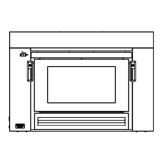
TESTED in compliance with AS/NZS 2918: 2001 Yunca recommends that competent trades persons carry out all installations (e.g. NZHHA Registered Installer), to obtain maximum performance and safe, efficient heating. A consent is required and we suggest you check with local building inspectors as by-laws do vary from area to area. - Page 4 Xander Wood Burner Dimensions (Fig 1) Blank fascia top panel (without vent) must be used for Masonry installations. (The vented fascia top panel is for zero clearance installations only) Fig. 1 Cavity Dimensions Cavity should be prepared using the following minimum clearances.
- Page 5 YUNCA Insert Flue Kit – Masonry (Complies with AS/NZS 2918:2001): Masonry Flue Kit consists of the following: 4.8m x 150mm stainless steel flue. 1.2m x 250mm galvanised liner. 1 x top cap & cowl (cone). Please Note: All flue joints must be sealed with flue sealing compound. Use stainless steel screws or rivets to join the flue pipe (three equally spaced places at each joint).
-
Page 6: Minimum Height Of Flue System Exit
Conditions for Flues (Fig. 4) The FLUE shall extend to: Not less than 600mm above the highest point on the roof if within 3.0m of that point, or Not less than 1000mm above the intersection point with the roof and not lower than any point of the roof within 3.0m. - Page 7 Xander Masonry Installation Thermal Clearances THERMAL CLEARANCES FRONT VIEW Fig. 5 THERMAL CLEARANCES CROSS SECTIONS Fig. 6 Install-Xander_Insert_MASONRY - 2017-06-26.doc www.yunca.co.nz Page 7 of 12...
- Page 8 Elevation Increase (mm) Table 2. Floor Protector Reductions for Masonry Installations Masonry Xander Insert Seismic Fixings Follow local Council’s specifications. Prior to installation, ensure the cavity floor is levelled. Also ensure the mantel face is perpendicular in relationship to the cavity floor.
- Page 9 Thermal Blanket Installation (Fig. 9) To ensure efficient operation it is recommended that thermal blanket (kaowool or – not supplied similar ) is affixed on the top, sides, and back of outer casing. Ensure rear air inlet is not obscured in any way. Blanket should be fastened to the outer casing in such a way that secure, long-term fitment is assured.
-
Page 10: Fan Installation
Fan Installation (Fig. 10) Take note of the entry and exit points for the cabling, and ensure measures are taken within the cavity to allow for this. Although the fan is controlled automatically by a thermostat it is recommended that an isolator switch is installed in conjunction. - Page 11 Xander Wiring Connections Attach the two black thermostat leads to the thermostat terminals. (Fig. 11) Note: Thermostat is mounted to the underside of the heater in the fan cavity. Attach the thermostat Earth wire to the chassis of the heater. (Fig.
- Page 12 Fig. 15 Fig. 16 Factory wired fascia circuit box Hard-wired fascia circuit box < END > These instructions, spare parts information, operation and maintenance guides may be downloaded from http://www.yunca.co.nz/installation-operation/ Install-Xander_Insert_MASONRY - 2017-06-26.doc www.yunca.co.nz Page 12 of 12...
Need help?
Do you have a question about the XANDER INSERT and is the answer not in the manual?
Questions and answers