Advertisement
Quick Links
Advertisement

Related Manuals for LightwaveRF LW825

Summary of Contents for LightwaveRF LW825
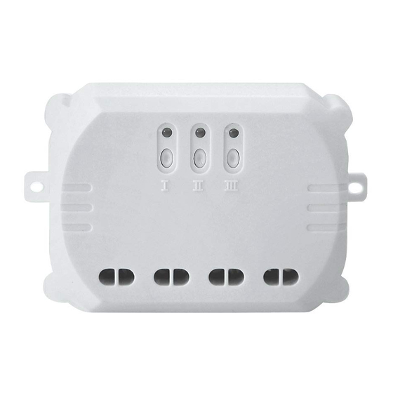
- Page 1 3-Way Relay Installation manual LW825 Professional Series www.lightwaverf.com...
- Page 2 EN 55022: 2010, EN 61000-3-2: 2006 +A1: 2009 +A2: 2009 Class A, EN 61000-3-3: 2008, EN61000-4-2: 2009, EN 61000-4-3: 2006 +A1: 2008 +A2: 2010, EN 61000-4-4: 2012, EN 61000-4-5: 2006, EN 61000-4-6: 2009, EN 61000-4-11: 2004 For and on behalf of LightwaveRF PLC ---------------------------------------- Name J Shermer...
- Page 3 You will also need suitable electrical screwdrivers. Help video & further guidance For additional guidance, and to watch a video that will help guide you through the installation process, please visit the support section on www.lightwaverf.com...
-
Page 4: Installation
Mounting hole. Wiring terminals. IMPORTANT: All LightwaveRF products can be legally DIY installed in your own home; however, if in doubt, always consult a qualified electrician or heating engineer. It is important to install this product in accordance with the following instructions. Failure to do so may void your warranty. -
Page 5: Wiring Terminals
Ensure that the device is mounted securely in a suitable housing (such as the LW823 Water- proof Housing). If conducting an insulation resistance test, all LightwaveRF products must be disconnected from the mains, or damage will occur. - Page 6 Installation Wiring the relay Turn o mains power first then wire each circuit as shown in the diagram. Linking buttons (I,II,III) Screw clamps Live Neutral (red or (blue brown wires) wires) Circuit 1 Circuit 2 Circuit 3 Mains 230V input IMPORTANT: Max.
- Page 7 2) Press an on or o button on the controller, or press ‘connect’ on the LightwaveRF App (the app instructions will explain how to do this). The LED will flash quickly to indicate a successful linking of that channel. NOTE: Each channel has 6 memory slots and therefore can be linked with up to 6 independent controllers at any one time.
- Page 8 If the distance between the transmitter and receiver is too great to achieve reliable operation, the LightwaveRF Signal Booster may be used in conjunction with this product to increase the range. IMPORTANT: relays should not be positioned within 30cm of one another, as their transmission signals may interfere and reduce the e ective operational range.
-
Page 9: Remote Operation
Remote operation Remote operation Control with the LightwaveRF App 1. Press the ‘on’ button on the App to turn the linked circuit on. 2. Press the ‘o ’ button on the App to turn the circuit o . Control using an on/o transmitter such as the handheld remote 1. -
Page 10: Specification
Technical specification Specification RF frequency: 433.92 MHz Input rating: 220-240V~ 50Hz. Output rating: 3000W Max. Dimensions: Width 98mm, Height 60mm, Depth 30mm Standby Energy Use: Less than 1W Warranty: 2 year standard warranty... - Page 11 Innovation Campus Birmingham Faraday Wharf Holt Street Birmingham B7 4BB www.lightwaverf.com Version 2.1...
Need help?
Do you have a question about the LW825 and is the answer not in the manual?
Questions and answers