Table of Contents
Advertisement
Quick Links
Tiny210/Smart210/Mini210S
User's Manual
REVISION
ORIGINATOR
SCR
REV DATE
0.1.0
Guangzhou FriendlyARM Co., Ltd
August 11st, 2014
Guangzhou FriendlyARM Computer Tech Co., Ltd Confidential:
Guangzhou FriendlyARM
This document and information contained in it shall not be reproduced
Computer Tech Co., Ltd
by, used by, or disclosed to others except as expressly authorized in
Guangzhou, China
writing by Guangzhou FriendlyARM Co., Ltd.
Copyright@2014
Address: Room 1705,Block A1, Longyuan Plaza, Longkouxi Road, Guangzhou, China, 510640
Website:
http://www.arm9.net
Sales:
+86-20-85201025
Tech Support: +86-13719442657
Fax:
+86-20-85261505
Email for Business and Cooperation:
capbily@163.com
Email for Tech Support: dev_friendlyarm@163.com
第 - 1 - 页
Advertisement
Table of Contents

Related Manuals for FriendlyARM Mini210S

Summary of Contents for FriendlyARM Mini210S
- Page 1 REV DATE 0.1.0 Guangzhou FriendlyARM Co., Ltd August 11st, 2014 Guangzhou FriendlyARM Computer Tech Co., Ltd Confidential: Guangzhou FriendlyARM This document and information contained in it shall not be reproduced Computer Tech Co., Ltd by, used by, or disclosed to others except as expressly authorized in Guangzhou, China writing by Guangzhou FriendlyARM Co., Ltd.
- Page 2 COPYRIGHT STATEMENT The content (content being images, text, programs and scripts) of this English manual is copyright © Guangzhou FriendlyARM Computer Tech Co., Ltd. All rights expressly reserved. Any content of the manual printed or downloaded may not be sold, licensed,...
-
Page 3: Table Of Contents
Index 210/S 210 ......................- 9 - NTRODUCTION TO MART 1.1 T 210 CPU B ..........................- 9 - OARD 1.1.1 Tiny210 CPU Board Hardware Feature ..................- 10 - 1.1.2 Tiny210 CPU Board Pin Spec ....................... - 11 - 1.1.3 Tiny210 CPU Board Interface and Port .................. - Page 4 2.1 M 210S B ..........................- 42 - OARD 2.1.1 Mini210S Overview ........................- 42 - 2.1.2 Mini210S Hardware Features ....................... - 43 - 2.1.3 Mini210S Board Dimension ......................- 45 - 2.2 M 210S B ..................- 46 -...
- Page 5 4.2.1 Burning Superboot to SD Card ....................- 79 - 4.2.2 Restore SD Card ..........................- 84 - 4.2.3 Notes to Users ..........................- 86 - 4.2.4 Configuring FriendlyARM.ini ...................... - 86 - 4.3 I ....................- 90 - NSTALL...
- Page 6 5.2.18 Backlight Control ........................- 137 - 5.2.19 Serial Port Assistant ........................- 140 - 5.2.20 LED Testing ..........................- 143 - 5.2.21 PWM Buzzer ..........................- 143 - 5.2.22 ADC Testing ..........................- 144 - 5.2.23 I2C-EEPROM Testing ....................... - 145 - 5.2.24 Setup Auto Run Utility.......................
- Page 7 6.2.2.4 ADC APIs ..........................- 180 - 6.2.2.5 EEPROM APIs ........................- 180 - 6.2.3 Code Samples ..........................- 181 - ....................... - 182 - INUX NSTALLATION AND AVIGATION 7.1 L ............................- 182 - INUX 7.2 I ......................- 182 - NSTALL AND LAY WITH INUX...
- Page 8 10.1.4 Install BSP and Examples ......................- 237 - 10.2 C CE 6 K ..............- 240 - OMPILE INDOWS ERNEL AND OOTLOADER 10.2.1 Compile Default Kernel Project ....................- 240 - 10.2.2 Change Serial Output ........................ - 247 - 10.2.3 Create SDK ..........................
-
Page 9: Introduction To Tiny210/Smart210
1 Introduction to Tiny210/Smart210 Tiny210 CPU Board vs Smart210 CPU Board The Tiny210 CPU board and Smart210 CPU board are both Cortex-A8 embedded processing board that uses the Samsung S5PV210 System On Chip (SOC). Its maximum frequency is up to 1GHz. The S5PV210 integrates the PowerVR SGX540 graphic engine with hardware support for 3D and can drive video playing on screens up to 1080P. -
Page 10: Tiny210 Cpu Board Hardware Feature
Android notepads, auto electronic devices, industrial applications, GPS systems and multimedia systems. 1.1.1 Tiny210 CPU Board Hardware Feature Samsung S5PV210, based on CortexTM-A8, 1GHz Integrated PowerVR SGX540 graphic engine Elegent 2D/3D graphic accelaration Up to 1080p@30fps hard decoded video playing, support MPEG4, H.263, H.264 etc ... -
Page 11: Tiny210 Cpu Board Pin Spec
Connector 2 x 60 pin 2.0 mm pitch header 1 x 30 pin 2.0 mm pitch header On Board Hardware 4 x LED (Green) Resource 1 x Power LED (Red) Power 4.7V to 5.6V (support sleep mode) PCB Dimension ... - Page 12 Spec Spec P1.1 VDD_5V P1.2 DGND P1.3 XvVD23 P1.4 XvVD22 P1.5 XvVD21 P1.6 XvVD20 P1.7 XvVD19 P1.8 XvVD18 P1.9 XvVD15 P1.10 XvVD14 P1.11 XvVD13 P1.12 XvVD12 P1.13 XvVD11 P1.14 XvVD10 P1.15 XvVD7 P1.16 XvVD6 P1.17 XvVD5 P1.18 XvVD4 P1.19 XvVD3 P1.20 XvVD2 P1.21...
- Page 13 P2.11 XuTXD2/UART_AUDIO_TXD P2.12 XuRXD2/UART_AUDIO_RXD P2.13 XuTXD3/RTSn2/UART_AUDIO_RTSn P2.14 XuRXD3/CTSn2/UART_AUDIO_CTSn P2.15 XspiMISO1 P2.16 XspiMOSI1 P2.17 XspiCLK1 P2.18 XspiCS1 P2.19 Xi2cSCL0 P2.20 Xi2cSDA0 P2.21 XmmcCLK0 P2.22 XmmcCMD0 P2.23 Xmmc0CDn P2.24 XEINT6_SD0_nWP P2.25 Xmmc0DATA0 P2.26 Xmmc0DATA1 P2.27 Xmmc0DATA2 P2.28 Xmmc0DATA3 P2.29 Audio_Xi2sSCLK0 P2.30 Audio_Xi2sCDCLK0 P2.31 Audio_Xi2sLRCK0 P2.32...
-
Page 14: Tiny210 Cpu Board Interface And Port
CON1.27 Xmmc3DATA2/Xmmc2DATA6 CON1.28 CAM_B_VSYNC CON1.29 Xmmc3DATA3/Xmmc2DATA7 CON1.30 CAM_B_HREF CON1.31 Xi2sCLK1/PCM_SCLK1/AC97_BITCLK CON1.32 CAM_B_FIELD CON1.33 Xi2sCDCLK1/PCM_EXTCLK1/AC97_RESETn CON1.34 CAM_B_CLKOUT CON1.35 Xi2sLRCK1/PCM_FSYNC1/AC97_SYNC CON1.36 CAMERA_B_GPIO0 CON1.37 Xi2sSDI1/PCM_SIN1/AC97_SDI CON1.38 CAMERA_B_GPIO1 CON1.39 Xi2sSDO1/PCM_SOUT1/AC97_SDO CON1.40 CAMERA_B_GPIO2 CON1.41 XpcmSCLK0/SPDIF_OUT0/Xi2sSCLK2 CON1.42 CAM_B_RESET CON1.43 XpcmEXTCLK0/SPDIF_EXTCLK/Xi2sCDCLK2 CON1.44 Xi2cSCL1 CON1.45 XpcmFSYNC0/LCD_FRM/Xi2sLRCK2 CON1.46 Xi2cSDA1 CON1.47 XpcmSIN0/Xi2sSDI2 CON1.48... -
Page 15: Led
1.1.3.2 LED LED is a commonly used status indication device. The Tiny210 has four programmable LEDs which are directly connected to GPIO and are on at a low level voltage. LED1 LED2 LED3 LED4 GPIO Pins GPJ_0 GPJ_1 GPJ_2 GPJ_3 1.2 Smart210 CPU Board The Smart210 CPU board has 2.0 mm spacing double row pitch headers (P1, P2, P3 and P4) which connect the Smart210 to a carrier board and extend most of the CPU’s... -
Page 16: Smart210 Cpu Board Hardware Feature
multimedia systems. 1.2.1 Smart210 CPU Board Hardware Feature Samsung S5PV210, based on CortexTM-A8, 1GHz Integrated PowerVR SGX540 graphic engine Elegent 2D/3D graphic accelaration Up to 1080p@30fps hard decoded video playing, support MPEG4, H.263, H.264 etc Up to 1080p@30fps hard decoded (Mpeg-2/VC1) video input ... -
Page 17: Smart210 Cpu Board Pin Spec
On Board Hardware 4 x LED (Green) Resource 1 x Power LED (Red) 1 x Audio(WM8960) 1 x Ethernet(DM9000) Power 4.7V to 5.6V (support sleep mode) PCB Dimension Six layered board Dimension: 74 x 55 x 11(mm) 1.2.2 Smart210 CPU Board Pin Spec Spec Spec... - Page 18 P1.11 Xmmc0DATA0 P1.12 Xmmc2DATA0 P1.13 Xmmc0DATA1 P1.14 Xmmc2DATA1 P1.15 Xmmc0DATA2 P1.16 Xmmc2DATA2 P1.17 Xmmc0DATA3 P1.18 Xmmc2DATA3 P1.19 Xmmc0CDn P1.20 Xmmc2CDn P1.21 XEINT16/KP_COL0 P1.22 XEINT24/KP_ROW0 P1.23 XEINT17/KP_COL1 P1.24 XEINT25/KP_ROW1 P1.25 XEINT18/KP_COL2 P1.26 XEINT26/KP_ROW2 P1.27 XEINT19/KP_COL3 P1.28 XEINT27/KP_ROW3 P1.29 XEINT10 P1.30 XEINT14 P1.31 XEINT11 P1.32...
- Page 19 P2.17 CAM_A_D6 P2.18 CAM_A_D7 P2.19 CAM_A_PCLK P2.20 CAM_A_VSYNC P2.21 CAM_A_HREF P2.22 CAM_A_FIELD P2.23 CAM_A_CLKenb P2.24 XhdmiTX1P P2.25 XhdmiTX0P P2.26 XhdmiTX1N P2.27 XhdmiTX0N P2.28 XhdmiTXCP P2.29 XhdmiTX2P P2.30 XhdmiTXCN P2.31 XhdmiTX2N P2.32 XEINT13/HDMI_HPD P2.33 Xi2cSDA1 P2.34 Xi2cSCL1 P2.35 XuoID P2.36 XspiCS0 P2.37 XuoDM P2.38...
-
Page 20: Smart210 Cpu Board Interface And Port
P3.23 Xm0DATA4 P3.24 Xm0DATA5 P3.25 Xm0DATA6 P3.26 Xm0DATA7 P3.27 Xm0DATA8 P3.28 Xm0DATA9 P3.29 Xm0DATA10 P3.30 Xm0DATA11 P3.31 Xm0DATA12 P3.32 Xm0DATA13 P3.33 Xm0DATA14 P3.34 Xm0DATA15 Spec Spec P4.1 CAM_B_D0 P4.2 XEINT20/KP_COL4 P4.3 CAM_B_D1 P4.4 XEINT21/KP_COL5 P4.5 CAM_B_D2 P4.6 XEINT22/KP_COL6 P4.7 CAM_B_D3 P4.8 XEINT23/KP_COL7 P4.9... -
Page 21: Jtag
GPIO Pins GPJ_0 GPJ_1 GPJ_2 GPJ_3 1.2.3.2 Jtag The Smart210 CPU board has five Jtag test points from which users can extend their applications. 1.3 Comparison of Smart210 and Tiny210 CPU Board Tiny210 CPU Board Smart210 CPU Board Address: Room 1705,Block A1, Longyuan Plaza, Longkouxi Road, Guangzhou, China, 510640 Website: http://www.arm9.net Sales:... -
Page 22: Tinysdk1312B Carrier Board
Samsung S5PV210, based on CortexTM-A8, 1GHz Integrated PowerVR SGX540 graphic engine Elegent 2D/3D graphic accelaration Up to 1080p@30fps hard decoded video playing, support MPEG4, H.263, H.264 etc Up to 1080p@30fps hard decoded (Mpeg-2/VC1) video input DDR2 ... -
Page 23: Tinysdk 1312B Carrier Board Hardware Feature
1.4.1 TinySDK 1312B Carrier Board Hardware Feature The TinySDK carrier board is a two-layer circuit board that demonstrates user-friendly reference designs with all the common interfaces. Components and interfaces (except the SD socket) are all located on one side for easy use. ... - Page 24 LCD3 interface (on the reverse): 40Pin, 0.5mm spacing, compatible with Mini2440/Mini6410 LCD, supports one wire precise touching LCD4 interface (reserved): 40Pin, 2mm spacing, compatible with Mini2440/Mini6410 LCD, supports one wire precise touching miniHDMI high definition interface (Type C) ...
-
Page 25: Tinysdk 1312B Carrier Board Layout
PCB Dimension Two Layered Board Dimension: 180 x 130(mm) Software Superboot Android 4.0 Android 2.3 Linux-3.0.8 + Qt4.8.5/Qtopia2/Qtopia4 Windows CE6.0 1.4.2 TinySDK 1312B Carrier Board Layout Obverse Address: Room 1705,Block A1, Longyuan Plaza, Longkouxi Road, Guangzhou, China, 510640 Website: http://www.arm9.net Sales:... -
Page 26: Tinyadk1312B Carrier Board
Reverse 1.5 TinyADK1312B Carrier Board The TinyADK is a common carrier board that works for the Tiny2416 CPU board, Tiny2451 CPU board, Tiny6410 CPU board and Tiny210 CPU board. Address: Room 1705,Block A1, Longyuan Plaza, Longkouxi Road, Guangzhou, China, 510640 Website: http://www.arm9.net Sales:... -
Page 27: Tinyadk 1312B Carrier Board Hardware Feature
1.5.1 TinyADK 1312B Carrier Board Hardware Feature The TinyADK carrier board is a two-layer circuit board that demonstrates user-friendly reference designs with all the common interfaces. Components and interfaces (except the SD socket) are all located on one side for easy use. ... - Page 28 Network 1 x 10/100M Ethernet interface(RJ45) using DM9000AEP Standard Configuration 1 x miniPCIe interface 2 x DB9 RS232 serial port 1 x miniUSB Slave-OTG 2.0 which can be extened via a 2.0mm socket 1 x 3.5mm stereotype audio output ...
-
Page 29: Tinyadk 1312B Carrier Board Layout
Android 2.3 Linux-3.0.8 + Qt4.8.5/Qtopia2/Qtopia4 Windows CE6.0 1.5.2 TinyADK 1312B Carrier Board Layout Obverse Address: Room 1705,Block A1, Longyuan Plaza, Longkouxi Road, Guangzhou, China, 510640 Website: http://www.arm9.net Sales: +86-20-85201025 Tech Support: +86-13719442657 Fax: +86-20-85261505 Email for Business and Cooperation: capbily@163.com Email for Tech Support: dev_friendlyarm@163.com 第... -
Page 30: 1305 Carrier Board
Reverse 1.6 Smart210 1305 Carrier Board Address: Room 1705,Block A1, Longyuan Plaza, Longkouxi Road, Guangzhou, China, 510640 Website: http://www.arm9.net Sales: +86-20-85201025 Tech Support: +86-13719442657 Fax: +86-20-85261505 Email for Business and Cooperation: capbily@163.com Email for Tech Support: dev_friendlyarm@163.com 第 - 30 - 页... -
Page 31: Smart210 1305 Carrier Board Hardware Feature
1.6.1 Smart210 1305 Carrier Board Hardware Feature LCD1 interface: 45Pin, 0.5mm spacing, compatible with Mini2440/Mini6410 LCD, supports one wire precise touching LCD2 interface: 40Pin, 0.5mm spacing, compatible with Mini2440/Mini6410 LCD, supports one wire precise touching LCD4 interface: 44Pin, 0.5mm spacing, compatible with Mini2440/Mini6410 LCD, supports one wire precise touching and capacitive touch HDMI high definition interface (Type A) LCDs supported from 3.5”... -
Page 32: Smart210 1305 Carrier Board Layout
Board Hardware 1 x I2C-EEPROM (256byte) for I2C bus test Resource 8 x Interrupt Style Push Button on module 1 x PWM buzzer 1 x backup battery for on board real time clock 1 x G-sensor chip External Resource 4 x TTL socket 1 x GPIO 1 x CMOS camera interface 1 x MIPI... -
Page 33: Tiny210/Smart210 Carrier Board Interface And Port
1.7 Tiny210/Smart210 Carrier Board Interface and Port 1.7.1 Power The carrier board requires 5V DC and has two power input ports. CN1 is the barrel jack for the 5V / 2A PSU included with SDK kits. The 4 pin white CON5 takes a connector with a “click in place”... -
Page 34: Usb
The UART0 and 3 are converted to RS232 (COM0 and COM3). You need to use the shipped cross serial cable to connect the board to a PC. Details of CON1,CON2,CON3, CON4 are as follows: CON2 Pin Spec(TTL) CON1, 3, 4 Pin Spec(TTL) COM0 Pin Spec(RS232) -
Page 35: Network Interface
the 210 and the other miniUSB (2.0) miniUSB Spec: miniUSB Pin Spec OTGID Vbus USB Host Pin Spec USB Host Pin Spec 1.7.4 Network Interface The 210 carrier board has a DM9000 LAN chip for adaptive 10/100M Ethernet. The RJ45 connector includes the magnetics. You can use ordinary Cat5 with RJ45 to connect to your router or switch. -
Page 36: User Button
microphone close to the audio source 1.7.6 User Button The Smart210 1305 carrier board has 8 buttons. The TinySDK/ADK 1312B has four user buttons connected directly to the CPU’s interrupt pins. They trigger low when closed. Button Interrupt EINT16 EINT17 EINT18 EINT19 GPIO... -
Page 37: Lcd Interface
1.7.7 LCD Interface For convenience in mounting various displays the 210 has three LCD connectors one of which is a 45pin and can work with both one wire touch LCDs and capacitive LCDs. The LCD control signals are the same on all connectors with horizontal and vertical scan, clock, enable, disable etc., and 8:8:8 models of RGB data. -
Page 38: Adc
VD16 VD17 VD18 VD19 VD20 VD21 VD22 VD23 PWM1/GPD0_1 XEINT10/GPH1_2 nRSTOUT VDEN VSYNC HSYNC VCLK I2CSCL2 XEINT14/GPH1_6 I2CSDA2 XEINT15/GPH1_7 Note: the S5PV210 has three I2Cs and here we use I2C2. Please refer to the schematics in the shipped CD for the exact connection details between each pin and CPU. -
Page 39: Pwm Buzzer
1.7.9 PWM Buzzer The on-board buzzer is controlled by PWM0, the diagram is shown below. PWM0 corresponds to GPD0_0 which can be configured as PWM output via software or used as a GPIO. 1.7.10 I2C-EEPROM The 210 has a direct connection to an AT24C08 – an I2C EEPROM which has a capacity of 256 bytes and is mainly for testing I2C bus. -
Page 40: Sdio/Gpio Interface
1.7.12 SDIO/GPIO Interface The S5PV210’s third SDIO is connected to CON13 on the TinySDK/ADK 1312B and to CON14 on the Smart210 SDK 1305, which is a 2.0mm spacing 20Pin header. It has SPI, I2C and four GPIOs The SDIO is usually used for SD-WiFi. CON13/CON14 Pin Spec CON13/CON14... -
Page 41: Cmos Camera
1.7.13 CMOS Camera The TinySDK/ADK 1312B and Smart210 SDK 1305 have a CMOS camera interface which is a 2.0mm spacing 20 pin header. Users can use our CAM130 cameras by connecting it to this header. Actually the CAM130 doesn’t have any circuits and it is a conversion board which applies the ZT130G2 module. -
Page 42: Introduction To Mini210S
2 Introduction to Mini210S The Mini210S development board is a powerful Cortex-A8 board offering a comprehensive solution integrating both hardware and software. It is designed, developed and distributed by FriendlyARM. It incorporates Samsung’s S5PV210 microprocessor whose maximum frequency is up to 1GHz. The S5PV210 integrates the PowerVR SGX540 graphic engine, supports 3D and can drive video playing on screens up to 1080P. -
Page 43: Mini210S Hardware Features
2.1.2 Mini210S Hardware Features Samsung S5PV210, based on CortexTM-A8, 1GHz Address: Room 1705,Block A1, Longyuan Plaza, Longkouxi Road, Guangzhou, China, 510640 Website: http://www.arm9.net Sales: +86-20-85201025 Tech Support: +86-13719442657 Fax: +86-20-85261505 Email for Business and Cooperation: capbily@163.com Email for Tech Support: dev_friendlyarm@163.com... - Page 44 PowerVR SGX540 graphic engine 2D/3D graphic accelaration Up to 1080p@30fps hard decoded video playing, support MPEG4, H.263, H.264 etc Up to 1080p@30fps hard decoded (Mpeg-2/VC1) video input DDR2 RAM 512M 32bit data bus, dual channels ...
-
Page 45: Mini210S Board Dimension
Superboot Android 4.0 Android 2.3 + Linux-2.6.35(kernel) Linux-3.0.8 + Qt4.8.5/Qtopia2/Qtopia4 WindowsCE 6.0 2.1.3 Mini210S Board Dimension Address: Room 1705,Block A1, Longyuan Plaza, Longkouxi Road, Guangzhou, China, 510640 Website: http://www.arm9.net Sales: +86-20-85201025 Tech Support: +86-13719442657 Fax: +86-20-85261505 Email for Business and Cooperation: capbily@163.com... -
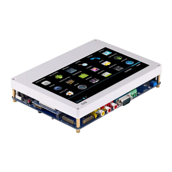
Page 46: Mini210S Board Jumpers And Diagram
2.2 Mini210S Board Jumpers and Diagram 2.2.1 Jumpers The Mini210S doesn’t have jumpers. 2.2.2 Board Diagram Here is the Mini210S’ diagram Address: Room 1705,Block A1, Longyuan Plaza, Longkouxi Road, Guangzhou, China, 510640 Website: http://www.arm9.net Sales: +86-20-85201025 Tech Support: +86-13719442657 Fax:... -
Page 47: Mini210S Ports And Interfaces
2.3 Mini210S Ports and Interfaces This section describes in detail each interface/port on the board. For more details please refer to the complete schematics (in PDF and Protel99SE) in the CDs shipped together with this product. 2.3.1 Power Address: Room 1705,Block A1, Longyuan Plaza, Longkouxi Road, Guangzhou, China, 510640 Website: http://www.arm9.net... -
Page 48: Serial Port
The Mini210S is powered by an external 5V power supply. It has two power inlets: CN1 is for 5V power adapter and the white CON13 is a 4 pin socket used to connect an external power supply when the board is embedded in a closed box. -
Page 49: Usb
For the Mini210S the UART0 is converted to RS232 (COM0). You need to use the shipped cross serial cable to connect the board to a PC. Details of CON1,CON2,CON3, CON4 are as follows: CON1、2 Pin Spec(TTL) CON3、4 Pin Spec(TTL) COM0... -
Page 50: Ethernet
I2S0 interface, and integrates a WM8960 CODEC module. The audio output is a 3.5mm green jack. The WM8960 has a D type amplifier therefore the Mini210S extends a Speaker socket(CON7) which can be connected to a 8 Ω 1W speaker. -
Page 51: Hdmi
2.3.6 HDMI The Mini210S has a mini HDMI output. The Mini210S extends the output to a Type C miniHDMI. Users can connect the board to an HDMI monitor or TV via a standard HDMI cable. Note: Android supports simultaneous output to both LCD and HDMI. - Page 52 When a board just comes off from production lines it is just a bare board without any data and we usually have to burn the first program to it through the JTAG interface. However since the S5PV210 supports booting from the TF card the JTAG is not significant to users any more.
-
Page 53: Led Indicator
GPJ_1 GPJ_2 GPJ_3 2.3.9 User Button The Mini210S has four user buttons all of which are extended from CPU’s interrupts and are triggered at a low level voltage. Address: Room 1705,Block A1, Longyuan Plaza, Longkouxi Road, Guangzhou, China, 510640 Website: http://www.arm9.net... -
Page 54: Matrix Keyboard
EINT16 EINT17 EINT18 EINT19 Multiplexed GPH2_0 GPH2_1 GPH2_2 GPH2_3 GPIO 2.3.10 Matrix Keyboard The S5PV210 supports 8x8 keyboards. The Mini210S extends the pins to CON12: CON12 Pin Pin Spec CON12 Pin Pin Spec XEINT16/KP_COL0 XEINT24/KP_ROM0 XEINT17/KP_COL1 XEINT25/KP_ROW1 XEINT18/KP_COL2 XEINT26/KP_ROW2 Address: Room 1705,Block A1, Longyuan Plaza, Longkouxi Road, Guangzhou, China, 510640 Website: http://www.arm9.net... -
Page 55: Lcd Interface
XEINT19/KP_COL3 XEINT27/KP_ROW3 XEINT20/KP_COL4 XEINT28/KP_ROW4 XEINT21/KP_COL5 XEINT29/KP_ROW5 XEINT22/KP_COL6 XEINT30/KP_ROW6 XEINT23/KP_COL7 XEINT31/KP_ROW7 VDD_3.3V VDD_3.3V Note: 1. CON12 is a standard IDC 2.0mm 20Pin socket. 2. XINT16/KP_COL0 means the pin can be multiplexed to interrupt XEINT16. This specification applies to other pins too. 3. - Page 56 LCD1 & LCD2 Pin Spec LCD1 & LCD2 Pin Spec VDD_5V VDD_5V VD10 VD11 VD12 VD13 VD14 VD15 VD16 VD17 VD18 VD19 VD20 VD21 VD22 VD23 PWM1/GPD0_1 XEINT10/GPH1_2 nRSTOUT VDEN VSYNC HSYNC VCLK I2CSCL2 XEINT14/GPH1_6 I2CSDA2 XEINT15/GPH1_7 Note: the S5PV210 has three I2Cs and here we use I2C2. Please refer to the schematics in the shipped CD for the exact connection details between each pin and CPU.
-
Page 57: Adc
2.3.12 ADC The Mini210S utilizes 6 ADC channels that the S5PV210 has for different purposes: - AIN0 is connected to an adjustable resistor W1 - AIN1, 2, 3, 4 and 5 are connected to CON6 which includes other GPIOs as well The S5PV210’s AD conversion can be configured as either 10-bit or 12-bit. -
Page 58: Iic-Eeprom
2.3.14 IIC-EEPROM The Mini210S has an EEPROM AT24C08 connected to CPU’s I2C0. It has 256 bytes memory and is mainly for testing I2C bus. Note: the S5PV210 has three I2Cs and here the Mini210 uses I2C0 2.3.15 Micro SD/TF Card The S5PV210 has four SDIO interfaces. -
Page 59: Cmos Camera
CON9 Pin Spec CON9 Pin Spec VDD_3.3V WIFI1_RST_GPIO/GPJ4_4 WIFI1_PWR_ONOFF/JPJ4_2 I2CSCL0 I2CSDA0 SPI0_MOSI0 SPI0_MISO0 SPI0_CLK0 SPI0_CS0 WIFI1_IO/GPJ4_1 WIFI1_PD_GPIO/GPJ4_3 MMC3_CLK MMC_CMD2 MMC_CDn2 WIFI1__nWP MMC3_DAT0 MMC3_DAT1 MMC3_DAT2 MMC3_DAT3 Please refer to the schematics in the shipped CD for the exact connection details between each pin and CPU. The information provided here is for reference 2.3.17 CMOS Camera The CMOS camera interface is extended to CON10. -
Page 60: Gpio
2.3.18 GPIO GPIO is the abbreviated form of “General Purpose Input Output”. The Mini210S has a 30 Pin 2.0mm spaced GPIO interface, i.e. CON6. In fact, CON6 has not only quite a few GPIO pins but also some CPU pins such as AD input, SPI, I2S, PCM and so on. -
Page 61: Mipi
CON6 Pin Spec CON6 Pin Spec VDD_3.3V ADCAIN1 EINT0/GPH0_0 ADCAIN2 EINT1/GPH0_1 ADCAIN6 EINT2/GPH0_2 ADCAIN7 EINT3/GPH0_3 ADCAIN8 EINT4/GPH0_4 ADCAIN9 EINT5/GPH0_5 SDA0 EINT6/GPH0_7 SCL0 EINT9/GPH1_1 SDA1 SPICLK1/GPB4 SCL1 SPICS1/GPB5 SDA2 SPIMISO1/GPB6 SCL2 SPIMISOI1/GPB7 nRSTOUT PWM2/GPD0_2 XPWRRGTON PWM3/GPD2_3 Please refer to the schematics in the shipped CD for the exact connection details between each pin and CPU. The information provided here is for reference 2.3.19 MIPI The MIPI interface is extended to CON16. - Page 62 CON6 Pin Spec CON6 Pin Spec VDD_3.3V VDD_5V mipiSDPCLK mipiMDPCLK mipiSDNCLK mipiMDNCLK mipiSDP0 mipiMDP0 mipiSDN0 mipiMDN0 mipiSDP1 mipiMDP1 mipiSDN1 mipiMDN1 mipiSDP2 mipiMDP2 mipiSDN2 mipiMDN2 mipiSDP3 mipiMDP3 mipiSDN3 mipiMDN3 Please refer to the schematics in the shipped CD for the exact connection details between each pin and CPU. The information provided here is for reference Address: Room 1705,Block A1, Longyuan Plaza, Longkouxi Road, Guangzhou, China, 510640 Website:...
-
Page 63: Software Features
Open source, migrated by FriendlyARM User button driver Open source, migrated by FriendlyARM SPI driver Open source,it comes with the kernel (2011.1.16) but is not verified by FriendlyARM I2C-EEPROM driver Open source, provided by Samsung PWM buzzer driver Open source, migrated by FriendlyARM... - Page 64 LCD back light driver: it adjust the board’s backlight up to 127 levels LCD driver(4.3”, 5”, 7” etc): it supports Open source, migrated by FriendlyARM. It drives screen rotation screens based on the initialization parameter “lcd=” USB Host driver: it supports flash drives, blue Open source, provided by Samsung tooth and so on.
-
Page 65: Android 4.0.3 Features
Open source, provided by Samsung USB to serial driver Open source, it comes with the kernel 3G driver Open source, migrated by FriendlyARM. It is a USB to Serial driver. Version: Android 2.3.1 Open source, Samsung BSP + FriendlyARM Android... - Page 66 Superboot-210 It supports SD card system burning and can Superboot is especially developed for enterprise install (YAFFS2) systems within 1.8 seconds. users It has a graphic interface and can display LCD info, hardware configurations, installation process It can automatically detect MMC/NAND booting mode.
- Page 67 screen rotation USB Host driver: it supports flash drives, blue tooth and so on. USB Device driver: it supports USB ADB SD card driver Serial port driver On board SD WiFi driver(Marvell8686) USB WiFi driver: it comes with the kernel but can only drive limited types USB WiFi driver: it supports more types Audio driver(WM8960: it supports audio...
-
Page 68: Linux Features
3G Wireless 3G Messaging HDMI Audio and Video Output Up to 1080p GSM Telephoning Tested with Huawei EM310 USB Flash Drive Up to 32G One Wire Precise Touching Back Light Adjusting up to 127 Levels GUI for Network Configuration Automatic IP Allocation 3.3 Linux Features Cross-compiler arm-linux-gcc-4.5.1-v6-vfp Same as Mini6410, by default it compiles with... - Page 69 LCD back light driver: it adjust the board’s backlight up to 127 levels LCD driver(4.3”, 5”, 7” etc): it supports Open source, migrated by FriendlyARM. It drives screen rotation screens based on the initialization parameter “lcd=” USB Host driver: it supports flash drives, blue Open source, provided by Samsung tooth and so on.
- Page 70 Qt-Extended-4.4.3 Open source for Cellphone based Qtopia, also called Qtopia4 Application The following programs are developed by FriendlyARM and are not open source 3G Communication 1) Support more than 100 USB cards for WCDMA, CDMA2000 and TD-SCDMA. 2) Support auto dialing on system startup...
-
Page 71: Wince6 Features
LED Control User Button Test I2C-EEPROM reading and writing LCD Test Utility Ping Test Utility USB Camera Utility CMOS Camera Utility Audio Recorder Web Browser Watchdog Network Configuration Utility Backlight Control Utility Language Setting Calibration Utility Qt4 Switch Utility Qtopia4 Switch Utility SMPlayer 3.4 WinCE6 Features Version... - Page 72 Serial port driver Audio driver(WM8960) Ethernet driver(DM9000) HDMI driver Application The following programs are developed by FriendlyARM and are not open source HDMI Support HDMI resolution settings, auto HDMI Address: Room 1705,Block A1, Longyuan Plaza, Longkouxi Road, Guangzhou, China, 510640 Website: http://www.arm9.net...
- Page 73 output on system startup LED Control User Button Test Audio Recorder Watchdog Network Configuration Utility Backlight Control Utility PWM Buzzer Serial Assistant Address: Room 1705,Block A1, Longyuan Plaza, Longkouxi Road, Guangzhou, China, 510640 Website: http://www.arm9.net Sales: +86-20-85201025 Tech Support: +86-13719442657 Fax: +86-20-85261505 Email for Business and Cooperation:...
-
Page 74: Getting Started
4 Getting Started By default, all our systems have been preinstalled with Android 4.0 (located in the shipped CDs’ directory /images/Android are superboot, zImage, root_android.img and so on) therefore you can easily boot the board and play. 4.1 System Setup and Configurations 4.1.1 Boot Option The 210 boards support booting from either SD card or Nand Flash. -
Page 75: Hardware Connection
4.1.2 Hardware Connection Please follow the steps below to hook up the board: Connect a 210 board’s serial port0 (Debug Serial Port) to a PC’s serial port with the shipped crossover serial cable (blue one) in the package Connect the 210 board’s Ethernet interface to a PC with the shipped crossover cable (this step can be skipped if you don’t need to connect to the internet) ... - Page 76 super terminal. In Windows9x, you need to install it by checking that option during installation. Windows2000 and later A common Linux desktop version has a similar terminal too and it is minicom. It is a command line utility which may not be easy for beginners. Interested users can search the internet for more resources.
- Page 77 Click on the “Yes” button and the “OK” button to the next step A popup window will require you to name this connection. In this example we typed “ttyS0”. Windows does not accept names like “COM1” that have already been used by the system.
- Page 78 After naming this connection another window will require you to select a serial port that will be used to connect the Tiny210 board. Here we selected COM1: Lastly, also the most important step is to set up the port properties. Note: you must select “No”...
-
Page 79: Burning Superboot To Sd Card
4.2 Burning Superboot to SD Card In order to boot from an SD card, you need to burn BIOS to it. FriendlyARM offers a flashing utility: SD-Flasher.exe which can burn our Superboot-210 to an SD card. Since Superboot-210 can detect an SD card and a NAND Flash it can boot both the SD card and the NAND Flash. - Page 80 Note: users complained that some notebook’s integrated SD card reader cannot work properly with card burning or reading. So far we haven’t encountered this issue and we suggest that you should try a common card reader in this case. Our SD-Flasher.exe formats a 130M space for the bootloader therefore an SD card whose memory is less than 256M cannot work and we recommend using one whose memory is at least 4G Step1: launch the SD-Flasher.exe in your shipped CD (under “\tools\”).
- Page 81 Step2: click on to select your Superboot file Step3: insert a FAT32 SD card into your host’s SD card socket (you can also use a USB and click on “Scan”, all card reader to connect to a PC), backup your data in the card recognized SD cards will be listed.
- Page 82 Just click on “Yes” After formatting is done you will be directed back to the main menu. Click on “Scan”, you will see that a “FriendlyARM” section available. Address: Room 1705,Block A1, Longyuan Plaza, Longkouxi Road, Guangzhou, China, 510640 Website: http://www.arm9.net...
- Page 83 Step5: click on “Fuse”, Superboot will be safely burned into the SD card. You can burn this card in WindowsXP without worrying about its FAT32 data being lost or damaged. The Superboot in your SD card is invisible. To verify it you can insert your SD card Address: Room 1705,Block A1, Longyuan Plaza, Longkouxi Road, Guangzhou, China, 510640 Website: http://www.arm9.net...
-
Page 84: Restore Sd Card
into your board’s SD card socket and switch S2 to the “SDBOOT” mode, reboot your board and if LED1 is flashing it is indicating that your Superboot is functioning. If you don’t see LED1 flashing or any output from your serial port it may indicate your burning was not successful. - Page 85 was. You can do it this way: launch SD-Flasher.exe as an administrator; click on “scan” and “ReFormat” you will see the following dialog Click on “Yes”. A moment later click on “Scan” again, you will find your card becomes “no” available and your card is restored successfully. Address: Room 1705,Block A1, Longyuan Plaza, Longkouxi Road, Guangzhou, China, 510640 Website: http://www.arm9.net...
-
Page 86: Notes To Users
For WindowsXP users we just set the burning mode to auto burning, the same as what Samsung does 4.2.4 Configuring FriendlyARM.ini When installing systems you will need the “FriendlyARM.ini” file. Its content is as follows: Address: Room 1705,Block A1, Longyuan Plaza, Longkouxi Road, Guangzhou, China, 510640 Website: http://www.arm9.net... - Page 87 FriendlyARM.ini File #This line cannot be removed. by FriendlyARM(www.arm9.net) CheckOneButton=No Action = Install OS = Android LCD-Mode = No LCD-Type = S70 LowFormat = Yes VerifyNandWrite = No CheckCRC32=No StatusType = Beeper | LED ################### Android 4.0.3 #################### Android-BootLoader = Superboot210.bin...
- Page 88 this item is usually set to “No” The default setting is “No” Action Set actions: Install/Run/Null Install – Install to the NAND Flash Run – Run from SD card Null – No action The default setting is“Install” Operating system to be loaded: Linux/WindowsCE6/Ubuntu/Android/UserBin ; “UserBin”...
- Page 89 2. To prevent our Superboot from being illegally copied we make it a rule that the first line of the ini file cannot be edited or deleted. It is: #This line cannot be removed. by FriendlyARM(www.arm9.net) Note: no space or any other character after the last “)” is allowed...
-
Page 90: Install Systems With Minitools
4.3 Install Systems with Minitools The Minitools utility is a FriendlyARM developed USB download tool which allows users to install systems more easily and conveniently. It has the following features: - Only need a USB cable: with the Minitools users only need a USB cable to install systems - One key action: no need to type any command. -
Page 91: Install On Linux
The minitools’ main window is shown below: 4.3.1.2 Install on Linux We tested installing the Minitools on Fedora9/Fedora15/Ubuntu12.04 64-bit systems. Please login execute installation root. Please copy “ ” in the “tools” directory from your DVD to your PC MiniTools-Linux-YYYYMMDD.tgz and untar the ball and run the “./start.sh”... -
Page 92: Install Systems With Minitools
2. Please copy the whole “images” directory from your DVD to the root directory of your SD card 3. Open the “images/friendlyARM.ini” and add the following line USB-Mode = yes Please follow the steps below to connect your board to your PC 1. - Page 93 On the left bottom of the window there is an LED which is green indicating the board is connected successfully. On the left bottom there is a button which can start your board directly without switching to NAND. Before install systems please select the system you want to install e.g. Linux and then its configuration will be presented as follows: Address: Room 1705,Block A1, Longyuan Plaza, Longkouxi Road, Guangzhou, China, 510640 Website:...
- Page 94 You can just click on the “images” button to select an “images” directory which contains complete installation files for all systems and the Minitools will show all the info listed in the FriendlyARM.ini. With the Minitools utility you can update either the whole system (all image files) or individual image files e.g.
- Page 95 After installation is done you can boot your board and enter your system. Note: sometime users complain that Minitools shows the board isn’t connected to PC. It is very likely that the USB download driver is not properly installed on your PC and you can try manually install the USB download driver which is under the Minitools directory in the shipped DVD Address: Room 1705,Block A1, Longyuan Plaza, Longkouxi Road, Guangzhou, China, 510640...
-
Page 96: Android Installation And Navigation
5 Android Installation and Navigation The 210 boards can run both Android2.3 and Android4. We migrated all the utilities we developed for the Mini6410 to the 210 boards. This not only meets most customers’ requirements but also enables users to focus on application development. Here is a table which lists all the software features the Tiny210 offers: 1080P High 2D/3D... -
Page 97: Installing And Playing With Android
Note: before read the following sections please burn Superboot to your SD card and copy corresponding installation files to your card. Step1: insert the SD card to a PC, open the “images\FriendlyARM.ini” file and modify it as follows: #This line cannot be removed. by FriendlyARM(www.arm9.net) - Page 98 LCD types images\Android\rootfs_android.img Android file sysem image images\FriendlyARM.ini Configuration file Step3: insert the SD card to the board’s SD socket and switch S2 to the SD side. Power on the board and you will hear a beep and see a progress bar on the LCD.
-
Page 99: Installing Android 2.3
Note: before read the following sections please burn Superboot to your SD card and copy corresponding installation files to your card. Step1: insert the SD card to a PC, open the “images\FriendlyARM.ini” file and modify it as follows: #This line cannot be removed. by FriendlyARM(www.arm9.net) - Page 100 LCD types images\Android2.3.1\rootfs_android.img Android file sysem image images\FriendlyARM.ini Configuration file Step3: insert the SD card to the board’s SD socket and switch S2 to the SD side. Power on the board and you will hear a beep and see a progress bar on the LCD.
- Page 101 If you are running Android for the first time you will see the following calibration screen: Click on “+”, follow it till the end position and Android will resume. After it is completely booted you will see the following screen: Address: Room 1705,Block A1, Longyuan Plaza, Longkouxi Road, Guangzhou, China, 510640 Website: http://www.arm9.net...
-
Page 102: Playing With Android
User button layout: The 210 boards has 4 buttons: Function Back Home Menu and Screen rotation 5.2 Playing with Android 5.2.1 Calibrate Touch Screen After you burn Android into your board you will see a calibration screen on the very first system boot. -
Page 103: Rotate Touch Screen
The following screen shows the system uses an ARM LCD: /dev/touchsreen (marked in red) Click on “+” and follow it to calibrate and you will enter the system after your calibration is done. If you don’t position your pen properly the calibration process will restart until you are done successfully. -
Page 104: Vertical Display/Horizontal Display
5.2.2.1 Vertical Display/Horizontal Display By default the board displays horizontally or vertically. Users can change that by following the steps below. Firstly please open the “init.rc” in the root directory, search for “ro.sf.hwrotation” and remove the “#”. This sets the rotation angle to 270 degrees. setprop ro.sf.hwrotation 270 If your OS is Android 2.3.1 after you make that change it will take into effect on system rebooting. -
Page 105: Display Auto Rotation
ro.sf.lcd_density=200 After you make the changes it will take into effect on system rebooting. 5.2.2.2 Display Auto Rotation If your 210 board has a g-sensor you can enble this function by setting up the following option. 5.2.3 Play MP3 Android can automatically detect MP3 files in the SD card. Address: Room 1705,Block A1, Longyuan Plaza, Longkouxi Road, Guangzhou, China, 510640 Website: http://www.arm9.net... -
Page 106: Adjust Volumn
5.2.4 Adjust Volumn Users can go to “Setting” -> “Sound” to adjust the volumn Address: Room 1705,Block A1, Longyuan Plaza, Longkouxi Road, Guangzhou, China, 510640 Website: http://www.arm9.net Sales: +86-20-85201025 Tech Support: +86-13719442657 Fax: +86-20-85261505 Email for Business and Cooperation: capbily@163.com Email for Tech Support: dev_friendlyarm@163.com 第... -
Page 107: Audio Recording
5.2.5 Audio Recording The DroidRecord utility can record and play audio. Double click on the icon to launch it. Please follow the screenshots below to start recording and play: 5.2.6 SD WiFi Address: Room 1705,Block A1, Longyuan Plaza, Longkouxi Road, Guangzhou, China, 510640 Website: http://www.arm9.net Sales:... - Page 108 The 210 boards can work with external SD-WIFI or USB WIFI modules. After Andoid loads please go to “settings”. Click on “Wi-Fi” and its “ON/OFF” button. Address: Room 1705,Block A1, Longyuan Plaza, Longkouxi Road, Guangzhou, China, 510640 Website: http://www.arm9.net Sales: +86-20-85201025 Tech Support: +86-13719442657 Fax:...
- Page 109 Select a source and type your username and password Address: Room 1705,Block A1, Longyuan Plaza, Longkouxi Road, Guangzhou, China, 510640 Website: http://www.arm9.net Sales: +86-20-85201025 Tech Support: +86-13719442657 Fax: +86-20-85261505 Email for Business and Cooperation: capbily@163.com Email for Tech Support: dev_friendlyarm@163.com 第...
-
Page 110: Cmos/Usb Camera
If your connections is successful you will see the following window. 5.2.7 CMOS/USB Camera The 210 boards can work with both USB cameras and CMOS cameras. Double click on the “Camera” icon Address: Room 1705,Block A1, Longyuan Plaza, Longkouxi Road, Guangzhou, China, 510640 Website: http://www.arm9.net Sales:... - Page 111 Double click on it you will see the following window Address: Room 1705,Block A1, Longyuan Plaza, Longkouxi Road, Guangzhou, China, 510640 Website: http://www.arm9.net Sales: +86-20-85201025 Tech Support: +86-13719442657 Fax: +86-20-85261505 Email for Business and Cooperation: capbily@163.com Email for Tech Support: dev_friendlyarm@163.com 第...
- Page 112 The round button on the bottom right is the snapshot button. Click on it you will see a picture taken. To browse all your pictures click on the top right button. We provide two HALs under Android 4 for CMOS, CCD and USB cameras. The CCD and CMOS cameras share the same HAL.
-
Page 113: Hdmi Output
2) Usually a USB camera displays horizontally. When you take pictures with a USB camera your pictures will be saved in the SD card if an SD card is inserted into your board. 3) By default the USB camera’s resolution is set to 544 x 288. Users can change the value of the item “ro.kernel.android.cam_def_size”... - Page 114 will be simultaneously output to your TV. You can configure the HDMI output format by following the steps below: Go to “Settings” to enter the “Display” menu Address: Room 1705,Block A1, Longyuan Plaza, Longkouxi Road, Guangzhou, China, 510640 Website: http://www.arm9.net Sales: +86-20-85201025 Tech Support: +86-13719442657...
-
Page 115: Hdmi Output Without Connecting Lcd
2) You can set your resolution to 480p/720p/1080p in “TV Resolution” 5.2.9 HDMI Output Without Connecting LCD The 210 boards can output to HDMI monitors without connecting an LCD. If you want to connect your 210 board only to an HDMI monitor without connecting an LCD you need to specify “LCD-Type”... - Page 116 You will see all the video files. Address: Room 1705,Block A1, Longyuan Plaza, Longkouxi Road, Guangzhou, China, 510640 Website: http://www.arm9.net Sales: +86-20-85201025 Tech Support: +86-13719442657 Fax: +86-20-85261505 Email for Business and Cooperation: capbily@163.com Email for Tech Support: dev_friendlyarm@163.com 第 - 116 - 页...
-
Page 117: Play Flash
When playing video in full screen you will see similar effects like the following screenshot: When connecting your board to a TV with an HDMI cable the audio and video output will be simultaneously output to your TV. 5.2.11 Play Flash Playing Flash on a web page needs flash plugins. -
Page 118: Gps
5.2.12 GPS FriendlyARM specially developed utilities for serial port based GPS devices in Android. Theoretically it should support USB based GPS devices as well. If your board connects to a USB GPS you need to change your GPS device to ttyUSB0 by editing the init.rc file to add a property “ro.kernel.android.gps”... -
Page 119: Configure Ethernet
internet, opened baidu’s map and used our GPS device to position: Note: to get better signals we suggest testing this function outdoors. 5.2.13 Configure Ethernet Android has an ethernet configuration utility Address: Room 1705,Block A1, Longyuan Plaza, Longkouxi Road, Guangzhou, China, 510640 Website: http://www.arm9.net Sales:... - Page 120 Click on “Ethernet Configuration” you can do either of the two settings: 1) Ethernet: turn on/off the Ethernet 2) Ethernet configuration: setup DHCP or static IP After Ethernet connection is successfully set you will see an icon as follows: Address: Room 1705,Block A1, Longyuan Plaza, Longkouxi Road, Guangzhou, China, 510640 Website: http://www.arm9.net Sales:...
-
Page 121: Dial-Up
5.2.14 3G Dial-Up 5.2.14.1 3G Manual Dial-Up We specially developed a 3G network utility for Android. It can automatically detect and support up to more than one hundred USB network cards for all these systems: WCDMA, CDMA2000 and TD-SCDMA. We have a list of the USB 3G cards that are supported (listed in later sections). - Page 122 Step3 after the 3G card is detected please click on its icon Address: Room 1705,Block A1, Longyuan Plaza, Longkouxi Road, Guangzhou, China, 510640 Website: http://www.arm9.net Sales: +86-20-85201025 Tech Support: +86-13719442657 Fax: +86-20-85261505 Email for Business and Cooperation: capbily@163.com Email for Tech Support: dev_friendlyarm@163.com 第...
- Page 123 Step6 if the connection is a success the orange icon will turn green and shows “Connected” and meanwhile FriendlyARM’s websites will be listed and a “3G” icon will show up on the upper left of the screen. Address: Room 1705,Block A1, Longyuan Plaza, Longkouxi Road, Guangzhou, China, 510640 Website: http://www.arm9.net...
- Page 124 Click on the green icon you will see the current network information Step7 you can click on “Hide” to run it on background Step8 Address: Room 1705,Block A1, Longyuan Plaza, Longkouxi Road, Guangzhou, China, 510640 Website: http://www.arm9.net Sales: +86-20-85201025 Tech Support: +86-13719442657 Fax: +86-20-85261505 Email for Business and Cooperation:...
- Page 125 Step9 try youku.com Try QQ browser to close the connection click on the “3G Network Status” icon to return to the Step10 main menu and click on “Disconnect” Address: Room 1705,Block A1, Longyuan Plaza, Longkouxi Road, Guangzhou, China, 510640 Website: http://www.arm9.net Sales: +86-20-85201025...
-
Page 126: Auto Dial-Up
5.2.14.2 3G Auto Dial-Up This utility also supports auto dial-up on system startup. Make sure your board connects to the internet and click on “3G Auto connection” in the dialog shown below. 3G auto dial-up will be effective on system reboot. Address: Room 1705,Block A1, Longyuan Plaza, Longkouxi Road, Guangzhou, China, 510640 Website: http://www.arm9.net... -
Page 127: Dial-Up And Messaging
On system startup, if there is a 3G icon shown on the top left it indicates that 3G auto dial-up is on (Note: 3G auto dial up by default uses the USB card you used before you set it therefore if you use a different card you need to reset it) 5.2.15 3G Dial-up and Messaging To use 3G to send and receive messages, you can set up 3G auto dial up and do it:... -
Page 128: Usb Bluetooth
If 3G auto dial up is set your USB device will act as a Modem. Please pull down the status bar if it has the service provider’s information it means you can send and receive messages 5.2.16 USB Bluetooth Android supports various USB bluetooth devices. Please connect your USB Bluetooth card to the USB host on the board, press the K3 button and click on “Settings”... - Page 129 After click on “Bluetooth” to turn it on it will search for nearby bluetooth devices and list them Address: Room 1705,Block A1, Longyuan Plaza, Longkouxi Road, Guangzhou, China, 510640 Website: http://www.arm9.net Sales: +86-20-85201025 Tech Support: +86-13719442657 Fax: +86-20-85261505 Email for Business and Cooperation: capbily@163.com Email for Tech Support: dev_friendlyarm@163.com 第...
-
Page 130: Bluetooth Communication
5.2.16.1 Bluetooth Communication Please get a cell phone which supports bluetooth and start the Bluetooth service. Boot your board with Android, go to “Bluetooth settings”, click on “Scan for devices” and it will find your cell phone. Address: Room 1705,Block A1, Longyuan Plaza, Longkouxi Road, Guangzhou, China, 510640 Website: http://www.arm9.net Sales:... - Page 131 Click on the cell phone name, type the password and click on “OK” At the same time there is a dialog shown on your cell phone prompting you to input a password. Type the same one you did on the board. If the connection is a success you will see the following window.
-
Page 132: Transfer Files To Cell Phone
5.2.16.2 Transfer Files to Cell Phone Please follow the steps described in the previous section to connect your board to a cell phone. Power on your board, open the “Gallery”, click a picture you want to transfer, click on the top right icon and then select “Bluetooth” to start transfering. Address: Room 1705,Block A1, Longyuan Plaza, Longkouxi Road, Guangzhou, China, 510640 Website: http://www.arm9.net... -
Page 133: Transfer Files To 210 Board
5.2.16.3 Transfer Files to 210 Board Please follow the steps described in the previous section to pair your board with a cell phone. After you send a file from your cell phone to your 210 board you will see the following window on your board Address: Room 1705,Block A1, Longyuan Plaza, Longkouxi Road, Guangzhou, China, 510640 Website:... -
Page 134: Usb Flash Drive
5.2.17 USB Flash Drive Android supports plug and play of USB flash drives up to a maximum of 32G (note: the drive should be formatted to FAT32). Insert your drive to the USB host and a flash drive icon will apprear on the bottom right of the screen Address: Room 1705,Block A1, Longyuan Plaza, Longkouxi Road, Guangzhou, China, 510640 Website:... - Page 135 Click on the icon you will see the following window Address: Room 1705,Block A1, Longyuan Plaza, Longkouxi Road, Guangzhou, China, 510640 Website: http://www.arm9.net Sales: +86-20-85201025 Tech Support: +86-13719442657 Fax: +86-20-85261505 Email for Business and Cooperation: capbily@163.com Email for Tech Support: dev_friendlyarm@163.com 第...
- Page 136 If you click on “Umount USB mass storage” you will safely umount your USB drive. If you click on “Open folder browser” you will lauch the ES file manager. By default the file manager lists all the files under “/sdcard”. You can go back to the root directory and then to “udisk”...
-
Page 137: Backlight Control
5.2.18 Backlight Control You may have noticed that after the system boots the backlight will turn off gradually if the touch screen doesn’t receive any touch. This is manipulated by the backlight control. Please go to “Display” -> “Brightness”. Address: Room 1705,Block A1, Longyuan Plaza, Longkouxi Road, Guangzhou, China, 510640 Website: http://www.arm9.net Sales:... - Page 138 Click on “Brightness” you will get the following window Click on “Brightness” you can set its brightness Address: Room 1705,Block A1, Longyuan Plaza, Longkouxi Road, Guangzhou, China, 510640 Website: http://www.arm9.net Sales: +86-20-85201025 Tech Support: +86-13719442657 Fax: +86-20-85261505 Email for Business and Cooperation: capbily@163.com Email for Tech Support: dev_friendlyarm@163.com 第...
- Page 139 By clicking on “Sleep” you can set a time period after which the backlight will be turned off. Address: Room 1705,Block A1, Longyuan Plaza, Longkouxi Road, Guangzhou, China, 510640 Website: http://www.arm9.net Sales: +86-20-85201025 Tech Support: +86-13719442657 Fax: +86-20-85261505 Email for Business and Cooperation: capbily@163.com Email for Tech Support: dev_friendlyarm@163.com 第...
-
Page 140: Serial Port Assistant
5.2.19 Serial Port Assistant To launch our serial port assistant utility, you can click on the “iTest” icon Click on “Serial Port Assistant” and you can set its parameters as follows: Address: Room 1705,Block A1, Longyuan Plaza, Longkouxi Road, Guangzhou, China, 510640 Website: http://www.arm9.net Sales:... - Page 141 After setup is done, click on “Connect” and if the connection is successful you will see the following messages from the serial port Address: Room 1705,Block A1, Longyuan Plaza, Longkouxi Road, Guangzhou, China, 510640 Website: http://www.arm9.net Sales: +86-20-85201025 Tech Support: +86-13719442657 Fax: +86-20-85261505 Email for Business and Cooperation:...
- Page 142 To send data to the serial port, you can type your messages in the left text box and click on “send”. Clicking on “Pause” pauses message sending and “Clean” removes all the received messages Note: 1) If a serial port doesn’t work you can check whether it is occupied by other applications by commanding “fuser filename”.
-
Page 143: Led Testing
5.2.20 LED Testing To test LEDs, please click on the “iTest” icon 5.2.21 PWM Buzzer To test PWM, please click on the iTest icon Address: Room 1705,Block A1, Longyuan Plaza, Longkouxi Road, Guangzhou, China, 510640 Website: http://www.arm9.net Sales: +86-20-85201025 Tech Support: +86-13719442657 Fax: +86-20-85261505 Email for Business and Cooperation:... -
Page 144: Adc Testing
On the window, you can type a frequency and “start” or adjust the frequency by clicking on “+” and “-”. To stop it you can click on “stop”. 5.2.22 ADC Testing To test ADC, please click on the “iTest” icon Address: Room 1705,Block A1, Longyuan Plaza, Longkouxi Road, Guangzhou, China, 510640 Website: http://www.arm9.net... -
Page 145: I2C-Eeprom Testing
5.2.23 I2C-EEPROM Testing To test “I2C-EEPROM” please click on the “iTest” icon Address: Room 1705,Block A1, Longyuan Plaza, Longkouxi Road, Guangzhou, China, 510640 Website: http://www.arm9.net Sales: +86-20-85201025 Tech Support: +86-13719442657 Fax: +86-20-85261505 Email for Business and Cooperation: capbily@163.com Email for Tech Support: dev_friendlyarm@163.com 第... -
Page 146: Setup Auto Run Utility
Users can set a utility to be automatically started on system boot in “/data/system/autostart_config.xml”. Here is a sample of this file: <?xml version="1.0" encoding="UTF-8"?> <appConfigs> <appConfig id="1"> <packageName>com.friendlyarm.net3gdialup</packageName> <mainActivityName>com.friendlyarm.net3gdialup.ActivityMain</mainActivityName> <autoStart>false</autoStart> </appConfig> Address: Room 1705,Block A1, Longyuan Plaza, Longkouxi Road, Guangzhou, China, 510640 Website: http://www.arm9.net... -
Page 147: Set Up Android Development Environment
<appConfig id="2"> <packageName>com.android.mms</packageName> <mainActivityName>com.android.mms.ui.ConversationList</mainActivityName> <autoStart>true</autoStart> </appConfig> </appConfigs> The utility’s name is bold is the one that will be automatically started on system boot. 5.3 Set up Android Development Environment What we mean by “set up Android Development Environment” includes the following three steps: Step1: install Fedora14 (32bit) Step2: install cross compilers... -
Page 148: Setup Android Compiler
#tar xvzf arm-linux-gcc-4.5.1-v6-vfp-20101103.tgz –C / Note: there is a space after “C” and “C” is a capital letter. These commands will install “arm-linux-gcc” “/opt/FriendlyARM/toolschain/4.5.1” Address: Room 1705,Block A1, Longyuan Plaza, Longkouxi Road, Guangzhou, China, 510640 Website: http://www.arm9.net Sales: +86-20-85201025 Tech Support: +86-13719442657... - Page 149 This is to edit the “/root/.bashrc” file (there is a “.” before “bashrc”). Update the last line with “export PATH=$PATH:/opt/FriendlyARM/toolschain/4.5.1/bin” in the opened file, save and exit the file Logout and login the system again (no need to reboot the system, just go to “start”->...
-
Page 150: Mktools Tool Chain
5.3.3 mktools tool chain To burn a target file system to the board you need to make an image first. The “mkyaffs2image-128M” is for for this. It is for creating an yaffs2 image whose page format is “1 Page= 2K Byte” and block format is “1 Block=128K” for SLC Nand Flash such as K9F2G08, K9F4G08 and K9K8G08. -
Page 151: Uncompress Source Code And Install Application Utilities
5.3.4 Uncompress Source Code and Install Application Utilities Firstly, create a working directory: /opt/FriendlyARM/mini210/android by running the following command #mkdir –p /opt/FriendlyARM/mini210/android All the source code in the following steps will be uncompressed in this working directory Get a Copy of Android Souce Code Package Create a temporary directory “/tmp/android”... -
Page 152: Configure And Compile Linux Kernel
Uncompress Android File System Execute the command below in “/opt/FriendlyARM/mini210/android” #cd /opt/FriendlyARM/mini210/android #tar xvzf /tmp/android/ rootfs_android-20110925.tar.gz This will create a rootfs_android directory Note: 20110925 is the date when we released it. 5.4 Configure and Compile Linux Kernel Android’s Linux kernel is a little bit different from a standard one but its configuration utility is the same. -
Page 153: Create And Run File System
With the mkyaffs2image-128M utility, you can make a yaffs2 image. The Android kernel by default supports this file system. Please run the commands below: #cd /opt/FriendlyARM/mini210/android/Android-2.3.1 #mkyaffs2image-128M rootfs_dir rootfs_android.img Address: Room 1705,Block A1, Longyuan Plaza, Longkouxi Road, Guangzhou, China, 510640 Website: http://www.arm9.net... -
Page 154: Android Application Development
6 Android Application Development This chapter introduces how to install Android SDK and Eclipse and debug programs for the 210 boards. We wish this could help Android beginners. 6.1 Set up Development Environment for Android Applications This section will introduce how to setup Android development on Windows 7 and how to use ADB. - Page 155 Check “Accept License Agreement” For Windows7 32bit systems you need to select “jdk-6u25-windows-i586.exe” to download the JDK. After download is completed, double click on it to install. After installation is completed you need to add the JDK command path to the Path environment variable.
-
Page 156: Download And Install Android Sdk
6.1.2 Download and Install Android SDK Please go to http://developer.android.com/sdk/ to download the latest Android SDK for windows. Please download the program marked in red in the screenshot shown below: (Note: up till May 18, 2011, the latest version is installer_r11-windows.exe) From the website users can get the latest version. - Page 157 “Cancel” to ignore it. Then you can find “Android SDK Tools” in the “Start” menu and click on “SDK Manager” to start it: By default the SDK is installed in drive C it is better to run it as an administrator otherwise data wrting will fail due to limited access to drive C.
-
Page 158: Download And Install Android 2.3 Packages
Now you can run the SDK you will be prompted to confirm if you want to run it as an administrator. Please click on “Yes” to go on. 6.1.3 Download and Install Android 2.3 Packages Run the SDK Manager as an administrator, select “Available Packages”, and click on the “>”... -
Page 159: Install Eclipse
want to restart ADB, just click on “Yes” to continue. 6.1.4 Install Eclipse Eclipse very popuplar Android. Please visit http://www.eclipse.org/downloads/ to download it. On the download page select “Eclipse IDE for Java Developers” You can also use the version “eclipse-java-helios-SR2-win32.zip” in the Android directory in the shipped CD. -
Page 160: Install Android Plugins
6.1.5 Install Android Plugins By following the above steps we have installed an Android SDK and Eclipse. In order to use the Android SDK in Eclipse you need to install an ADT plugin as well: Please visit http://developer.android.com/sdk/eclipse-adt.html#installing, find the link for ADT and download it. -
Page 161: Configure Eclipse
Exit Eclipse, replace the Eclipse directory with these files to complete the installation. 6.1.6 Configure Eclipse Start Eclipse, click on “Window” on the main page and select “Preferences”. On the left side select “Android” and click on “Browser” to point to the installation path. By default it is “C:\Program Files\Android\android-sdk”: Click on “OK”... -
Page 162: Set Up Android Simulator
6.1.7 Set up Android Simulator Move to “Android SDK Tools” in the start menu and click on “SDK Manager”. Click on “New…” in the “Android SDK and AVD Manager” dialog and a “Create new Android Virtual Device(AVD)” dialog will pop up. Input “Android-AVD” in the Name field, select “Android 2.3.3 - API Level 10”... -
Page 163: Create Android Program
Select your simulator, click on “Start” and “Launch” in the “Launch Option” dialog to start it: 6.1.8 Create Android Program 6.1.9 Create HelloMini210 Project In this section we will create an Android project “HelloMini210” to test our development environment. Start Eclipse and go to “File->New->Project...”. Address: Room 1705,Block A1, Longyuan Plaza, Longkouxi Road, Guangzhou, China, 510640 Website: http://www.arm9.net... - Page 164 In the “New Project” dialog, select “Android->Android Project” and click on “Next” In the “New Android Project” dialog type the following information or check the following options: 1) Project Name: HelloMini210 2) Build Target: Android 2.3.3 3) Appication name:HelloMini210 Address: Room 1705,Block A1, Longyuan Plaza, Longkouxi Road, Guangzhou, China, 510640 Website: http://www.arm9.net Sales:...
- Page 165 4) Package name:com.mini210 5) Create Activity:MainActivity Click on “Finish” to complete the wizard and return to the main window: Close the “Welcome” page and the project view will be presented. On the left side click on “src -> com.mini210 -> MainActivity.java” you will see the source code: Address: Room 1705,Block A1, Longyuan Plaza, Longkouxi Road, Guangzhou, China, 510640 Website: http://www.arm9.net...
-
Page 166: Run Hellomini210 In Simulator
6.1.10 Run HelloMini210 in Simulator To compile and run “HelloMini210” please select the “HelloMini210” project in “Package Explorer”and then click on the “run” button or go to “Run->Run As->Android Application”. The Android simulator will automatically start and it may take a while. After it fully loads it will run “HelloMini210”: In the following sections we will debug and run this program on the Tiny210 6.1.11 Set up Android Debug Environment... - Page 167 “Android SDK and AVD Manager” page, go to “Third party Add-ons” click on “>” to expand the list and check “Google Usb Driver package” as follows: Click on the “Install Selected” button, check “Accept All” in the “Choose Packages to Install” dialog and click on “Install” to begin download. It may take a while. After download is completed power on a 210 board and wait until Android fully loads.
- Page 168 Right click on “S5P OTG-USB”, select “Update Driver Software”, click on “Browse my computer for driver software” and “Browse”to select a USB driver. By default it is “C:\Program Files\Android\android-sdk\extras\google\usb_driver”. Click on “Next” to continue. Address: Room 1705,Block A1, Longyuan Plaza, Longkouxi Road, Guangzhou, China, 510640 Website: http://www.arm9.net Sales:...
-
Page 169: Test Adb On 210
Click on the “Install” button on the above dialog and a moment later you will see the following information which indicates that your installation is completed. 6.1.11.2 Test ADB on 210 6.1.11.3 Add ADB Commands to Path Environment Variable Please follow the steps below to add the ADB path to the Path variable Address: Room 1705,Block A1, Longyuan Plaza, Longkouxi Road, Guangzhou, China, 510640 Website: http://www.arm9.net... - Page 170 1) Right click on “My Computer” -> “Property”, on the left side click on the “Advanced System Settings” button 2) Click on the “System Variables” button 3) Go to “System Variables”, double click on the “Path” variable and add “C:\Program Note: there is a “;”.
-
Page 171: Test Adb
6.1.11.4 Test ADB Check device status Power on your 210 board and connect it to your PC via the mini USB cable. Please type the command below in your DOS commandline utility # adb devices If you can see the following information it means your device is successfully connected to your PC: Enter the ADB Shell Please run the command below to enter the terminal:... -
Page 172: Run Programs On 210 Board With Usb Adb
6.1.11.5 Run Programs on 210 Board with USB ADB Start Eclipse and open the “HelloMini210” project. On the left side click on the “HelloMini210” project in the Package Explorer, click on “Properties” and the “Properties for HelloMini210” dialog will pop up: Click on “Run/Debug Settings”, select “HelloMini210”... - Page 173 Click on “OK” to save Now select “HelloMini210” and click on the “Run” button on the tools bar or go to “Run->Run As->Android Application”. On the “Android Device Chooser” dialog select “Choose a running Android device” and select the “2.3.1” target device (Tiny210), and click on “OK”...
-
Page 174: Debug Android Programs On 210
A moment later “HelloMini210” will be running on the Tiny210: 6.1.11.6 Debug Android Programs on 210 Exit the HelloMini210 if you are running it. Go to “Open Perspective->Debug” on the Eclipse main window you will enter the debug view. We can set a break point and Address: Room 1705,Block A1, Longyuan Plaza, Longkouxi Road, Guangzhou, China, 510640 Website: http://www.arm9.net... -
Page 175: Access Hardware In Andorid
6.2 Access Hardware in Andorid For users to fully use and acces the 210 hardware resources FriendlyARM developed a library named “libfriendlyarm-hardware.so” which can be used to access and operate the hardware resources on the 210 including serial port, buzzer, EEPROM and ADC. -
Page 176: How To Use "Libfriendlyarm-Hardware.so
In this section we will describe how to use the libfriendlyarm-hardware.so library. 6.2.1 How to Use “libfriendlyarm-hardware.so” FriendlyARM has included the libfriendlyarm-hardware.so library in Android since the March 2011 version. It is in the following directory device/Samsung/smdkv210/prebuilt/libfriendlyrm-hardware.so On the 210 Android system it is in the “/system/lib/libfriendlyarm-hardware.so”... - Page 177 System.loadLibrary("friendlyarm-hardware"); catch (UnsatisfiedLinkError e) { Log.d("HardwareControler", "libfriendlyarm-hardware library not found!"); Start Eclipse and select your project list and “Refresh” it now you will see the...
-
Page 178: Libfriendlyarm-Hardware.so Apis
To use the HardwareControler APIs you need to add the following line to your code which introduces the HardwareControler class: import com.friendlyarm.AndroidSDK.HardwareControler; Now you will be able to call HardwareControler APIS and we will show you some examples in the following sections: 6.2.2 libfriendlyarm-hardware.so APIs... - Page 179 Return Value: When the device is opened successfully it will return a file descriptor which can be used to read、write and select the device otherwise it will returns -1. write( fd: file descriptor Write data to an opened device. data: data to write to the device byte[] data) Return Value: When the operation succeeds it will...
-
Page 180: Led Apis
6.2.2.2 LED APIs LED APIs: APIs Parameters and Return Value Comment setLedState( Open an LED ledID: LED you want to access (0~3) ledID, ledState: 1 is on,0 is off ledState ) Return Value: If this operation succeeds it will return 0 otherwise it will return -1 6.2.2.3 PWM APIs PWM Buzzer APIs:... -
Page 181: Code Samples
pos: position where data to be written write operaration). pos, (0~255) byte byteData); byteData: data to be written Note: this operation is time consuming. It costs about 10 ms. Return Value: If this operation succeeds it will return the number of characters written otherwise it will return -1. -
Page 182: Linux Installation And Navigation
Note: before read the following sections please burn Superboot to your SD card and copy corresponding installation files to your card. Step1: insert the SD card to a PC, open the “images\FriendlyARM.ini” file and modify it as follows: #This line cannot be removed. by FriendlyARM(www.arm9.net) - Page 183 LCD types images\Linux\rootfs_qtopia_qt4.img Linux file sysem image images\FriendlyARM.ini Configuration file Step3: insert the SD card to the board’s SD socket and switch S2 to the SD side. Power on the board and you will hear a beep and see a progress bar on the LCD.
-
Page 184: Calibrate Touch Screen
If you are running Linux for the first time you will see the following calibration screen: 7.2.2 Calibrate Touch Screen Note: if you didn’t calibrate well you can delete the “etc/pointercal” and reboot the system, or reflash the board or use a USB mouse to calibrate after Linux is loaded. In the following two scenarios the calibration screen will be brought up: 1. -
Page 185: Introduction To Main Pages
completely booted you will see the following screen: The following screen shows the system uses an ARM LCD: /dev/touchsreen (marked in red) 2. After enter the system go to “start->setting” and click on the “calibrate” icon you will see the above screen too. 7.2.3 Introduction to Main Pages After Linux qtopia is loaded you will see the following screen. -
Page 186: Smplayer
“start” on the left bottom you will see five sub-menus which are the same as these five pages. The “FriendlyARM” page contains software utilities that are all developed or migrated by us. All the other utilities and documents in other pages are open source 7.2.4 SMPlayer... - Page 187 If you want to close the HDMI output or reset the HDMI resolution you can go to the “FriendlyARM” page and click on the HDMI icon. Uncheck “Auto start HDMI-output on boot” and check the resolution you want from the list and save it.
-
Page 188: Hdmi Output Without Connecting Lcd
You can configure the HDMI setting in the “/root/Settings/HDMI.conf” file. [HDMISetting] AutoStart = yes Resolution = 720P-60Hz SupportResolution1=720P-60Hz SupportResolution2=1080I-50Hz “AutoStart” defines whether the HDMI output will be started on system boot. “Resolution” defines the HDMI resolution and the following values are available: 1080P-60Hz, 1080P-50Hz, 1080I-60Hz,... -
Page 189: Play Video
7.2.8 Play Video Go to the “Application” page, click on the “video” icon, select a video file and click on “play”. This player can fluently play H.264/H.263/Mpeg4 files. 7.2.9 Image Viewer Go to the Application page, click on the “pictures” icon and you will be able to browse pictures Address: Room 1705,Block A1, Longyuan Plaza, Longkouxi Road, Guangzhou, China, 510640 Website:... -
Page 190: Auto Mount Of Sd Card
All files in the MMC/SD card will be listed in the “Documents” page. Note: this auto mount function is developed by FriendlyARM and currently it can only recognize the card’s first section and formats of VFAT/FAT32/FAT16. -
Page 191: Calculator
Click on the “Applications” -> “Storage” you will see the card’s data 7.2.11 Calculator Go to “Applications” and click on the calculator icon. You can select “Simple”, “Fraction”, “Scientific” and “Conversion”. 7.2.12 Terminal Go to “Applications”, click on the terminal icon and you will be able to type Linux Address: Room 1705,Block A1, Longyuan Plaza, Longkouxi Road, Guangzhou, China, 510640 Website: http://www.arm9.net... -
Page 192: File Manager
7.2.13 File Manager Go to “FriendlyARM”, click on the file manager icon and you will see your system’s file structure: 7.2.14 Ethernet Setting Address: Room 1705,Block A1, Longyuan Plaza, Longkouxi Road, Guangzhou, China, 510640 Website: http://www.arm9.net Sales: +86-20-85201025 Tech Support: +86-13719442657... -
Page 193: Wireless Network
Go to “FriendlyARM”, click on the network setting and you will be able to see the following screenshot You can set your network parameters and “save” it to the “/etc/eth0-setting”. 7.2.15 Wireless Network This section will introduce how to configure the SD WiFi and USB WiFi. -
Page 194: Wireless Ap
7.2.15.2 Wireless AP After launching the setting utility it will automatically search for an AP and list all SSIDs and their signal strengths. After an AP is found to connect to it you can click on its ESSID and input its password Address: Room 1705,Block A1, Longyuan Plaza, Longkouxi Road, Guangzhou, China, 510640 Website: http://www.arm9.net... - Page 195 Click on “connect” If the connection is successful it will show “Connected” If you started the Ethernet before you start the wireless you will see the following dialog Address: Room 1705,Block A1, Longyuan Plaza, Longkouxi Road, Guangzhou, China, 510640 Website: http://www.arm9.net Sales: +86-20-85201025...
- Page 196 which prompts you to close the Ethernet. You need to close the Ethernet. Click on “Net Detail” you will see the wireless network’s details After your connection is successful, click on “close” to minimize the utility Now you can surf the internet Address: Room 1705,Block A1, Longyuan Plaza, Longkouxi Road, Guangzhou, China, 510640 Website: http://www.arm9.net...
-
Page 197: Disconnect Wireless Network
7.2.15.3 Disconnect Wireless Network To disconnect the wireless network you can just click on “Disconnect” 7.2.15.4 IP Configuration On the wireless utility window click on “Configure IP” you will see the following dialog: Address: Room 1705,Block A1, Longyuan Plaza, Longkouxi Road, Guangzhou, China, 510640 Website: http://www.arm9.net Sales:... - Page 198 Click on the “IP Setting” pull-down list you will be able to select “DHCP” or “Configure IP Manually” Address: Room 1705,Block A1, Longyuan Plaza, Longkouxi Road, Guangzhou, China, 510640 Website: http://www.arm9.net Sales: +86-20-85201025 Tech Support: +86-13719442657 Fax: +86-20-85261505 Email for Business and Cooperation: capbily@163.com Email for Tech Support: dev_friendlyarm@163.com 第...
-
Page 199: Ping Test
After configure your network please go to “FriendlyARM” and click on “Ping Testing” 7.2.17 Web Browser Go to “FriendlyARM”, click on “Browser”, open the soft keypad on the left bottom and you can type a website in the address bar. -
Page 200: Led Test
Go to “FriendlyARM” and click on “LED Testing” 7.2.19 EEPROM Reading and Writing Go to “FriendlyARM” and click on “I2C-EEPROM”. Click on “Write Data below into EEPROM via IIC” you will see the writing process Click on “Read EEPROM Data via IIC” you will see the reading process... -
Page 201: Linux Application Development
Note: before read the following sections please burn Superboot to your SD card and copy corresponding installation files to your card. Step1: insert the SD card to a PC, open the “images\FriendlyARM.ini” file and modify it as follows: #This line cannot be removed. by FriendlyARM(www.arm9.net) - Page 202 It should be a 24bit bmp. images\CE\NK.bin CE kernel and file sysem image images\FriendlyARM.ini Configuration file Step3: insert the SD card to the board’s SD socket and switch S2 to the SD side. Power on the board and you will hear a beep and see a progress bar on the LCD.
-
Page 203: Running Windowsce6 From Sd Card
Note: before read the following sections please burn Superboot to your SD card and copy corresponding installation files to your card. Step1: insert the SD card to a PC, open the “images\FriendlyARM.ini” file and modify it as follows: #This line cannot be removed. by FriendlyARM(www.arm9.net) -
Page 204: Windowsce6 Application Development
It should be a 24bit bmp. images\CE\NK.bin CE kernel and file sysem image images\FriendlyARM.ini Configuration file Step3: insert the SD card to the board’s SD socket and switch S2 to the SD side. Power on the board and you will hear a beep and see WinCE is being loaded. - Page 205 your PC is installed with the Tiny6410’s development environment you need to delete the following directory before you install the Tiny210 BSP C:\WINCE600\PLATFORM\COMMON\SRC\SOC\S3C6410_SEC_V1 If you do want to install both the Tiny6410 and Tiny210’s BSPs please try this way on VMWare Note: the following software installation steps are based on MS Windows 7(Flagship).
- Page 206 installation file, users need to go to MS’ home site to download its trial version) Visual Studio 2005 (trial version: http://download.microsoft.com/download/e/1/4/e1405d9e-47e3-404c-8b09-489437b27f b0/En_vs_2005_Pro_90_Trial.img) Visual Studio 2005 Service Pack 1(VS80sp1-KB926601-X86-ENU.exe) http://www.microsoft.com/downloads/details.aspx?familyid=bb4a75ab-e2d4-4c96-b39d -37baf6b5b1dc&displaylang=en Visual Studio 2005 Service Pack 1 Update for Windows Vista (VS80sp1-KB932232-X86-ENU.exe) http://www.microsoft.com/downloads/details.aspx?FamilyID=90E2942D-3AD1-4873- A2EE-4ACC0AACE5B6&displaylang=en)
-
Page 207: Install Visual Studio 2005 And Patches
Windows Embedded CE 6.0 R2 http://www.microsoft.com/downloads/details.aspx?FamilyId=F41FC7C1-F0F4-4FD6-9 366-B61E0AB59565&displaylang=en Windows Embedded CE 6.0 R3 http://www.microsoft.com/downloads/details.aspx?FamilyID=BC247D88-DDB6-4D4A -A595-8EEE3556FE46&displaylang=ja&displaylang=en Tencent QQ (Third Party Software) http://www.microsoft.com/downloads/details.aspx?FamilyID=527042f7-bb5b-4831-a6a d-5081808824ec&displaylang=en WesttekFileViewers6.exe http://www.microsoft.com/downloads/details.aspx?FamilyID=d2fd14eb-7d5c-428b-951 c-343f910047c1&displaylang=en Please follow the order in the list to install these software components. Note: WinCE6.0’s Platform Builder is a plug-in of VS2005 therefore users need to install VS2005 first. - Page 208 Step 2: In the following dialog click on “Install Visual Studio 2005” Address: Room 1705,Block A1, Longyuan Plaza, Longkouxi Road, Guangzhou, China, 510640 Website: http://www.arm9.net Sales: +86-20-85201025 Tech Support: +86-13719442657 Fax: +86-20-85261505 Email for Business and Cooperation: capbily@163.com Email for Tech Support: dev_friendlyarm@163.com 第...
- Page 209 Step 3 Wait a while and click on “Next” Step 4: type a serial number and click on “Next” Address: Room 1705,Block A1, Longyuan Plaza, Longkouxi Road, Guangzhou, China, 510640 Website: http://www.arm9.net Sales: +86-20-85201025 Tech Support: +86-13719442657 Fax: +86-20-85261505 Email for Business and Cooperation: capbily@163.com Email for Tech Support: dev_friendlyarm@163.com 第...
- Page 210 Step 5: Select “Full” and click on “Next” Step 6: Begin to install Visual Studio 2005 Address: Room 1705,Block A1, Longyuan Plaza, Longkouxi Road, Guangzhou, China, 510640 Website: http://www.arm9.net Sales: +86-20-85201025 Tech Support: +86-13719442657 Fax: +86-20-85261505 Email for Business and Cooperation: capbily@163.com Email for Tech Support: dev_friendlyarm@163.com 第...
- Page 211 Step 7: After VS2005 installation is done, click on “Finish” Address: Room 1705,Block A1, Longyuan Plaza, Longkouxi Road, Guangzhou, China, 510640 Website: http://www.arm9.net Sales: +86-20-85201025 Tech Support: +86-13719442657 Fax: +86-20-85261505 Email for Business and Cooperation: capbily@163.com Email for Tech Support: dev_friendlyarm@163.com 第...
- Page 212 Click on “Exit” to complete Step Install Visual Studio 2005 Service Pack double click “VS80sp1-KB926601-X86-ENU.exe” Address: Room 1705,Block A1, Longyuan Plaza, Longkouxi Road, Guangzhou, China, 510640 Website: http://www.arm9.net Sales: +86-20-85201025 Tech Support: +86-13719442657 Fax: +86-20-85261505 Email for Business and Cooperation: capbily@163.com Email for Tech Support: dev_friendlyarm@163.com 第...
- Page 213 Step 9: wait a while and click on “OK” on the following dialog Step 10: Accept the aggrement Step 11: Please wait for the installation Step 12: Click “OK” to complete installation Address: Room 1705,Block A1, Longyuan Plaza, Longkouxi Road, Guangzhou, China, 510640 Website: http://www.arm9.net Sales:...
- Page 214 Step 13: Install Visual Studio 2005 Service Pack 1 Update for Windows Vista, double click on VS80sp1-KB932232-X86-ENU.exe Step 14: Click on “OK” to continue Step 15: accept the aggreement Address: Room 1705,Block A1, Longyuan Plaza, Longkouxi Road, Guangzhou, China, 510640 Website: http://www.arm9.net Sales:...
- Page 215 Step 16: Please wait for the installation Step 17: After installation is done click on “OK” to complete the installation Step 18: Install Visual Studio 2005 Service Pack 1 ATL Security Update, double click on VS80sp1-KB971090-X86-INTL.exe Address: Room 1705,Block A1, Longyuan Plaza, Longkouxi Road, Guangzhou, China, 510640 Website: http://www.arm9.net Sales:...
- Page 216 Step 19: Wait a while please click on “OK” to continue Step 20: accept the agreement Step 21: Wait for the installation Address: Room 1705,Block A1, Longyuan Plaza, Longkouxi Road, Guangzhou, China, 510640 Website: http://www.arm9.net Sales: +86-20-85201025 Tech Support: +86-13719442657 Fax: +86-20-85261505 Email for Business and Cooperation:...
-
Page 217: Install Windows Ce 6 And Patches
Step 22: After installation is done, click on “OK” to complete Now all Windows 7 and Visual Studio 2005 components have been installed 10.1.2 Install Windows CE 6 and Patches In this section we will show you how to install Windows CE6 and Platform Builder. Note: to install Windows CE6 on Windows 7 you need to do it as administrator. - Page 218 Step 2: in the command line window go to the installation directory type the installation program “Windows Embedded CE 6.0.msi” to begin installation Address: Room 1705,Block A1, Longyuan Plaza, Longkouxi Road, Guangzhou, China, 510640 Website: http://www.arm9.net Sales: +86-20-85201025 Tech Support: +86-13719442657 Fax: +86-20-85261505 Email for Business and Cooperation:...
- Page 219 Step 3: click on “Next” to continue Address: Room 1705,Block A1, Longyuan Plaza, Longkouxi Road, Guangzhou, China, 510640 Website: http://www.arm9.net Sales: +86-20-85201025 Tech Support: +86-13719442657 Fax: +86-20-85261505 Email for Business and Cooperation: capbily@163.com Email for Tech Support: dev_friendlyarm@163.com 第 - 219 - 页...
- Page 220 Step 4: type a serial number and click on “Next” to continue Step 5: accept the agreement and click on “Next” to continue Address: Room 1705,Block A1, Longyuan Plaza, Longkouxi Road, Guangzhou, China, 510640 Website: http://www.arm9.net Sales: +86-20-85201025 Tech Support: +86-13719442657 Fax: +86-20-85261505 Email for Business and Cooperation:...
- Page 221 Step 6: select options as below and click on “Next” to continue Step 7: click on “Next” to continue Address: Room 1705,Block A1, Longyuan Plaza, Longkouxi Road, Guangzhou, China, 510640 Website: http://www.arm9.net Sales: +86-20-85201025 Tech Support: +86-13719442657 Fax: +86-20-85261505 Email for Business and Cooperation: capbily@163.com Email for Tech Support: dev_friendlyarm@163.com 第...
- Page 222 Step 8: click on “Install” Step 9: Installation begins Address: Room 1705,Block A1, Longyuan Plaza, Longkouxi Road, Guangzhou, China, 510640 Website: http://www.arm9.net Sales: +86-20-85201025 Tech Support: +86-13719442657 Fax: +86-20-85261505 Email for Business and Cooperation: capbily@163.com Email for Tech Support: dev_friendlyarm@163.com 第...
- Page 223 Step 10: after installation is done, click on “Finish” Step 11: Install “Windows Embedded CE 6.0 Platform Builder Service Pack 1.msi”. Follow the instructions in Step 1 to install it. Address: Room 1705,Block A1, Longyuan Plaza, Longkouxi Road, Guangzhou, China, 510640 Website: http://www.arm9.net Sales:...
- Page 224 Step12: Click on “Next” to continue: Step 13: Accept the agreement and click on “Next” continue Address: Room 1705,Block A1, Longyuan Plaza, Longkouxi Road, Guangzhou, China, 510640 Website: http://www.arm9.net Sales: +86-20-85201025 Tech Support: +86-13719442657 Fax: +86-20-85261505 Email for Business and Cooperation: capbily@163.com Email for Tech Support: dev_friendlyarm@163.com 第...
- Page 225 Step 14: click on “Next” to continue Step 15: wait for the installation process Address: Room 1705,Block A1, Longyuan Plaza, Longkouxi Road, Guangzhou, China, 510640 Website: http://www.arm9.net Sales: +86-20-85201025 Tech Support: +86-13719442657 Fax: +86-20-85261505 Email for Business and Cooperation: capbily@163.com Email for Tech Support: dev_friendlyarm@163.com 第...
- Page 226 Step 16: after installation is done, click on “Finish” Step 17: Install “Windows Embedded CE 6.0 R2.msi” Address: Room 1705,Block A1, Longyuan Plaza, Longkouxi Road, Guangzhou, China, 510640 Website: http://www.arm9.net Sales: +86-20-85201025 Tech Support: +86-13719442657 Fax: +86-20-85261505 Email for Business and Cooperation: capbily@163.com Email for Tech Support: dev_friendlyarm@163.com 第...
- Page 227 Step 18: Click on “Next” to continue Step 19: accept the agreement and click on “Next” to continue Address: Room 1705,Block A1, Longyuan Plaza, Longkouxi Road, Guangzhou, China, 510640 Website: http://www.arm9.net Sales: +86-20-85201025 Tech Support: +86-13719442657 Fax: +86-20-85261505 Email for Business and Cooperation: capbily@163.com Email for Tech Support: dev_friendlyarm@163.com 第...
- Page 228 Step 20: Click on “Next” to continue Step21: Click on “Next” to continue Address: Room 1705,Block A1, Longyuan Plaza, Longkouxi Road, Guangzhou, China, 510640 Website: http://www.arm9.net Sales: +86-20-85201025 Tech Support: +86-13719442657 Fax: +86-20-85261505 Email for Business and Cooperation: capbily@163.com Email for Tech Support: dev_friendlyarm@163.com 第...
- Page 229 Step 22: Installation begins: Step 23: After installation is done click on “Finish” Address: Room 1705,Block A1, Longyuan Plaza, Longkouxi Road, Guangzhou, China, 510640 Website: http://www.arm9.net Sales: +86-20-85201025 Tech Support: +86-13719442657 Fax: +86-20-85261505 Email for Business and Cooperation: capbily@163.com Email for Tech Support: dev_friendlyarm@163.com 第...
- Page 230 Step 24: Install “Windows Embedded CE 6.0 R2.msi” Step 25: Click on “Next” to continue Address: Room 1705,Block A1, Longyuan Plaza, Longkouxi Road, Guangzhou, China, 510640 Website: http://www.arm9.net Sales: +86-20-85201025 Tech Support: +86-13719442657 Fax: +86-20-85261505 Email for Business and Cooperation: capbily@163.com Email for Tech Support: dev_friendlyarm@163.com 第...
- Page 231 Step 26: accept the agreement and click on “Next” to continue Step 27: Click on “Next” to continue Address: Room 1705,Block A1, Longyuan Plaza, Longkouxi Road, Guangzhou, China, 510640 Website: http://www.arm9.net Sales: +86-20-85201025 Tech Support: +86-13719442657 Fax: +86-20-85261505 Email for Business and Cooperation: capbily@163.com Email for Tech Support: dev_friendlyarm@163.com 第...
- Page 232 Step 28: Installation begins: Step 29: After installation is done, click on “Finish” Address: Room 1705,Block A1, Longyuan Plaza, Longkouxi Road, Guangzhou, China, 510640 Website: http://www.arm9.net Sales: +86-20-85201025 Tech Support: +86-13719442657 Fax: +86-20-85261505 Email for Business and Cooperation: capbily@163.com Email for Tech Support: dev_friendlyarm@163.com 第...
-
Page 233: Install Third Party Software Tencent Qq
“WinCEPB60-101231-Product-Update-Rollup-Armv4I.msi”. Step30: Install download address is http://www.microsoft.com/download/en/details.aspx?displaylang=en&id=1127 10.1.3 Install Third Party Software Tencent QQ Step1: enter the QQ installation directory and double click on setup.exe to begin installation Step 2: click on “Next” to continue Address: Room 1705,Block A1, Longyuan Plaza, Longkouxi Road, Guangzhou, China, 510640 Website: http://www.arm9.net Sales:... - Page 234 Step 3: Click on “Next” to continue Address: Room 1705,Block A1, Longyuan Plaza, Longkouxi Road, Guangzhou, China, 510640 Website: http://www.arm9.net Sales: +86-20-85201025 Tech Support: +86-13719442657 Fax: +86-20-85261505 Email for Business and Cooperation: capbily@163.com Email for Tech Support: dev_friendlyarm@163.com 第 - 234 - 页...
- Page 235 Step 4: Accept the agreement and click on “Next” to continue Step 5: click on “Next” to continue Address: Room 1705,Block A1, Longyuan Plaza, Longkouxi Road, Guangzhou, China, 510640 Website: http://www.arm9.net Sales: +86-20-85201025 Tech Support: +86-13719442657 Fax: +86-20-85261505 Email for Business and Cooperation: capbily@163.com Email for Tech Support: dev_friendlyarm@163.com 第...
- Page 236 Step 6: Wait a while Step 7: click on “Close” to complete Address: Room 1705,Block A1, Longyuan Plaza, Longkouxi Road, Guangzhou, China, 510640 Website: http://www.arm9.net Sales: +86-20-85201025 Tech Support: +86-13719442657 Fax: +86-20-85261505 Email for Business and Cooperation: capbily@163.com Email for Tech Support: dev_friendlyarm@163.com 第...
-
Page 237: Install Bsp And Examples
10.1.4 Install BSP and Examples Note: the 6410’s WinCE development environment cannot co-exist with the 210’s. If your PC is installed with the Tiny6410’s development environment you need to delete the following directory before you install the Tiny210 BSP C:\WINCE600\PLATFORM\COMMON\SRC\SOC\S3C6410_SEC_V1 If you do want to install both the Tiny6410 and Tiny210’s BSPs please try this way on VMWare The Tiny210’s BSP has only one installation file Mini210-CE6-Suite-1212. - Page 238 Step 2: click on “Install” Step 3: Installation begins: Address: Room 1705,Block A1, Longyuan Plaza, Longkouxi Road, Guangzhou, China, 510640 Website: http://www.arm9.net Sales: +86-20-85201025 Tech Support: +86-13719442657 Fax: +86-20-85261505 Email for Business and Cooperation: capbily@163.com Email for Tech Support: dev_friendlyarm@163.com 第...
- Page 239 Step 4: After installation is done click on “Close” to complete After installation is done a Mini210 BSP directory will be created under “WinCE600\PLATFORM” Address: Room 1705,Block A1, Longyuan Plaza, Longkouxi Road, Guangzhou, China, 510640 Website: http://www.arm9.net Sales: +86-20-85201025 Tech Support: +86-13719442657 Fax: +86-20-85261505 Email for Business and Cooperation:...
-
Page 240: Compile Windowsce 6 Kernel And Bootloader
There are three directories in “WinCE600\OSDesigns”: Mini210 – Simplified Chinese Mini210-en – English Mini210-tw – Traditional Chinese 10.2 Compile WindowsCE 6 Kernel and Bootloader It takes much time to compile a WinCE kernel therefore we provide a workable CE image in our DVD. 10.2.1 Compile Default Kernel Project Now we will use VS2005 to compile our Mini210 BSP. - Page 241 Step 1: go to “Start” -> “Programs” -> “Microsoft Visual Studio 2005” -> “Microsoft Visual Studio 2005” (abbreviated as VS2005) Step 2: Click on “Exit Visual Studio” Address: Room 1705,Block A1, Longyuan Plaza, Longkouxi Road, Guangzhou, China, 510640 Website: http://www.arm9.net Sales: +86-20-85201025 Tech Support: +86-13719442657...
- Page 242 Step 3: Set up VS2005’s property. Go to “Start” -> “Programs” -> “VS2005” -> “VS2005”, right click and select “Property” Step 4: On the pop up dialog, click on “Compatibility”, check the following options and Address: Room 1705,Block A1, Longyuan Plaza, Longkouxi Road, Guangzhou, China, 510640 Website: http://www.arm9.net Sales:...
- Page 243 save Step 5: go to “Start” -> “Programs” -> “Vs2005” -> “VS2005”, click on “Continue”. You will run VS2005 as administrator Step 6: you will see the following working window Address: Room 1705,Block A1, Longyuan Plaza, Longkouxi Road, Guangzhou, China, 510640 Website: http://www.arm9.net Sales:...
- Page 244 Step 7: go to “File” -> “Open” -> “Project/Solution…” Address: Room 1705,Block A1, Longyuan Plaza, Longkouxi Road, Guangzhou, China, 510640 Website: http://www.arm9.net Sales: +86-20-85201025 Tech Support: +86-13719442657 Fax: +86-20-85261505 Email for Business and Cooperation: capbily@163.com Email for Tech Support: dev_friendlyarm@163.com 第...
- Page 245 Step 8: Open the default Mini210 file “C:\WINCE600\OSDesigns\Mini210” Step 9: After a while you will see the following dialog Address: Room 1705,Block A1, Longyuan Plaza, Longkouxi Road, Guangzhou, China, 510640 Website: http://www.arm9.net Sales: +86-20-85201025 Tech Support: +86-13719442657 Fax: +86-20-85261505 Email for Business and Cooperation: capbily@163.com Email for Tech Support: dev_friendlyarm@163.com 第...
- Page 246 Step 10: Go to “Build” -> “Advanced Build Commands” -> “Clean Sysgen” to compile the kernel. Step 11: after compilation is done, an NK.bin and NK.nb0 will be created in “C:\WINCE600\OSDesigns\Mini210\Mini210\RelDir\Mini210_ARMV4I_Release\” Address: Room 1705,Block A1, Longyuan Plaza, Longkouxi Road, Guangzhou, China, 510640 Website: http://www.arm9.net Sales:...
-
Page 247: Change Serial Output
10.2.2 Change Serial Output Open the options.h file you can define the serial ports’ output: #define DEBUG_PORT DEBUG_UART_NONE The default definition doesn’t output debug messages to any serial port. The DEBUG_PORTcan be set to the following values: DEBUG_UART_NONE -> No output message DEBUG_UART0 ->... -
Page 248: Install Sdk
Step 2: a while later an SDK will be created Step SDK1.msi will created under “C:\WINCE600\OSDesigns\Mini210\Mini210\SDKs\SDK1\MSI” 10.2.4 Install SDK If you don’t want to make your own SDK you can use the one included in the shipped Address: Room 1705,Block A1, Longyuan Plaza, Longkouxi Road, Guangzhou, China, 510640 Website: http://www.arm9.net Sales:... -
Page 249: Address: Room 1705,Block A1, Longyuan Plaza, Longkouxi Road, Guangzhou, China
DVD. It is under “WindowsCE6\Mini210-CE6-SDK.msi”. To develop applications for the Tiny210 in VS2005 you need to install an SDK. Here are the steps to install it. Step 1: double click on “Mini210-CE6-SDK.msi” and click on “Next” Step 2: accept the agreement and click on “Next” Step 3: type your company name and user name and click on “Next”... - Page 250 Step 4: Click on “Complete” to continue Step 5: click on “Next” to continue Address: Room 1705,Block A1, Longyuan Plaza, Longkouxi Road, Guangzhou, China, 510640 Website: http://www.arm9.net Sales: +86-20-85201025 Tech Support: +86-13719442657 Fax: +86-20-85261505 Email for Business and Cooperation: capbily@163.com Email for Tech Support: dev_friendlyarm@163.com 第...
- Page 251 Step 6: click on “Install” to continue Step 7: Wait for installation Address: Room 1705,Block A1, Longyuan Plaza, Longkouxi Road, Guangzhou, China, 510640 Website: http://www.arm9.net Sales: +86-20-85201025 Tech Support: +86-13719442657 Fax: +86-20-85261505 Email for Business and Cooperation: capbily@163.com Email for Tech Support: dev_friendlyarm@163.com 第...
- Page 252 Step 8: After installation is done, click on “Finish” to complete Address: Room 1705,Block A1, Longyuan Plaza, Longkouxi Road, Guangzhou, China, 510640 Website: http://www.arm9.net Sales: +86-20-85201025 Tech Support: +86-13719442657 Fax: +86-20-85261505 Email for Business and Cooperation: capbily@163.com Email for Tech Support: dev_friendlyarm@163.com 第...
Need help?
Do you have a question about the Mini210S and is the answer not in the manual?
Questions and answers