Table of Contents
Advertisement
Quick Links
Advertisement
Table of Contents
Troubleshooting

Summary of Contents for CallerID Vertex VoIP Caller ID
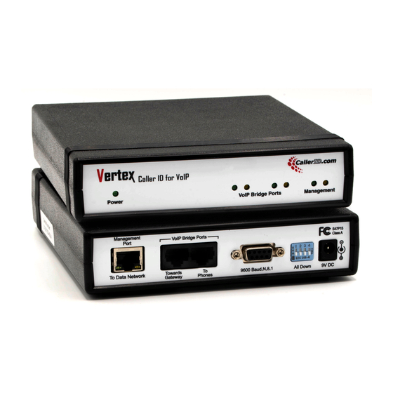
- Page 1 Vertex VoIP Caller ID (Version 2.0 - 12/01/2017)
-
Page 2: Table Of Contents
Table of Contents Overview ..............................1 Critical Information ........................... 1 Types of VoIP ............................2 Installation ..............................2 Basics ............................... 2 Installation Instructions ..........................3 Hosted VoIP Connection Diagrams ..................... 4 Figure 1 - Phones and Computers on the same Switch ..............4 Figure 2 - VoIP Phones connected to Auxiliary Switch .............. - Page 3 VCT Station Routing Tab ........................15 Edit Routing Table ..........................16 VCT Advanced Tab ..........................19 VoIP Signaling Format ........................19 Network Packet Capture ........................20 Bootup (Radio Button) ........................20 Other Diagnostic Tools VoIP Phones/Devices ........................20 SIP Call Flow ..........................20 Default View ..........................
- Page 4 Appendix A - Troubleshooting ....................... 35 Setup Troubleshooting ........................35 Vertex Configuration Tool (VCT) will not detect the Vertex hardware ..........35 Amber Lights not Coming On or Flashing ..................36 Restoring to Factory Defaults ......................37 Reboot causes Unit to Lose Parameters Previously Set ..............37 Restoring Vertex to Previous Working Settings .................
-
Page 5: Overview
Overview The Vertex unit is designed to capture Caller ID and other telephony signaling on VoIP phone calls and send this information to computers. Depending on the software running on the computer, applications such as Caller ID popup screens for delivery, dispatch, phone billing, and logging calls are available. Critical Information The Vertex is designed to capture only standard non-encrypted SIP (Session Initiation Protocol). -
Page 6: Types Of Voip
Types of VoIP There are basically two types of VoIP service, Hosted VoIP and Managed VoIP. Hosted VoIP is defined by the service provider performing all voice switching, routing, messages on hold, call queuing, and other functions. In most cases, the end user needs only to connect VoIP phones to their network. -
Page 7: Installation Instructions
Close any Caller ID services associated; they may bind to ports needed for setup. Download and install the Vertex Configuration Tool (VCT) at www.VCT.CallerID.com. Launch VCT. Upon startup, VCT must detect the Vertex hardware. If not, turn off any third-party Firewalls or virus checking programs, re-check Ethernet connections, and try again. -
Page 8: Hosted Voip Connection Diagrams
Hosted VoIP Connection Diagrams (3 Figures) Hosted VoIP is defined by the service provider performing all voice switching, routing, messages on hold, call queuing, and other functions. In most cases, the end user needs only to connect VoIP phones to their network. Any significant programming and configuration is done by the service provider. -
Page 9: Figure 2 - Voip Phones Connected To Auxiliary Switch
Figure 2 - VoIP Phones connected to Auxiliary Switch For architectures employing an auxiliary network switch to connect the phones, we recommend installing the Vertex between the auxiliary switch and the main switch. The original connection is removed and the Gateway Router is connected to the Network Switch through the VoIP Bridge ports on the Vertex. -
Page 10: Figure 3 - Separate Voip And Data Networks
Figure 3 - Separate VoIP and Data Networks This network architecture is seen with controlled POS systems that supply a separate router enabling all their equipment to reside within its own subnet. Remove the original VoIP connection (dotted line below) and route the connection carrying all VoIP traffic through the two Vertex “VoIP Bridge Ports”. If the POS application collects Caller ID via Ethernet, connect the Vertex “Management Port”... -
Page 11: Managed Voip Connection Diagram
VoIP Connection Diagram Managed Managed VoIP involves additional equipment on site that handles most of the VoIP switching, routing, and call processing. Various terms and acronyms apply to Managed VoIP including SIP trunking, Asterisk PBX, ISDN PRI, and T1 feeds. There are many types of architectures available using particular combinations of these and other items. -
Page 12: Installation Checks
Note: Turn off any 3rd party firewalls before VCT installation. Depending on your Internet Brower, download and install the latest version from: www.VCT.CallerID.com https://secure.callerid.com/vct/ Make sure that the PC you are running VCT on is connected to the same subnet as the Vertex. -
Page 13: Vertex Configuration Key Parameters
3520 for both inbound or outbound traffic. Note that the installer will allow the exceptions based on the application name within Windows firewall. • The Vertex default IP address is 192.168.1.90 and is set for DHCP. If your network IP scheme is not similar and the Vertex did not obtain DHCP, the router may not recognize the hardware. -
Page 14: Vct Main Tab
VCT Main Tab Serial Number. Decoding of the serial number is as follows. In this example, the serial number is 21-171009-01-24 21 - Type of unit - Vertex 17 - Year Built - 2017 10 - Month Built - October 09 - Day Built - 01 - Unit number built that day 24 - Hardware revision... -
Page 15: Voice Channels Permitted
Voice Channel licenses can be upgraded with a code from CallerID.com. Normally, there is a cost associated. Unit Number. This can be used when multiple Vertex units are placed in the same location. -
Page 16: Vct Time Tab
VCT Time Tab Last Date/Time from Unit. The ideal method of setting the Vertex's internal time clock is retrieving it from National Time Servers (NITS). This can only occur if the Data Gateway MAC address is correct and a valid DNS server is listed. If the NITS transaction does not occur, the Vertex will obtain the current time and date from the VoIP SIP packets, if this information is present. -
Page 17: Vct Data Output Tab
Selections for the data output Destination and Format will be specific to the software being used for Caller ID popup screens or your intended application needs. The format options available match the options of CallerID.com analog devices. This enables the Vertex to be compatible with existing software written for our analog products. -
Page 18: Station Routing
Known Formats (Button). This is a list of software applications and software companies that have integrated to CallerID.com products. Use the search text box to search for either software or company name. Applying your selection will set the VCT to the appropriate output format and apply changes to the Vertex Hardware. -
Page 19: Vct Station Routing Tab
VCT Station Routing Tab The Station Routing method of data delivery is designed for locations having many VoIP phones and multiple voice channels available on each phone. Your software application must be written in a particular manor to take advantage of the Station Routing method. Station Routing sends individual Caller ID records to each computer. -
Page 20: Edit Routing Table
Edit Routing Table The Edit Routing Table allows you to detect phones and assign them to individual computers based on the computers static IP address. A workstation name will be assigned to each phone/computer combination. Select the "Start Detecting Phones" button. Wait until all your phones are detected and select Stop Detection, or you can simply let the 2 minute process time out. - Page 21 Select an entry on the left and press the Add to Routing Table button. Enter a workstation name and the IP address on the computer associated with that phone. Add the remaining detected phone entries to the Routing Table. Select the "Save and Close" button to save entries to the Vertex.
- Page 22 The main Station Routing tab will display your entries.
-
Page 23: Vct Advanced Tab
VCT Advanced Tab This section is used for diagnostic purposes to instruct the Vertex is set to dump raw network packets to the program. The VCT can analyze SIP packets to show the call flow and other detailed data that may be used to configure the Vertex. -
Page 24: Network Packet Capture
4. Select Stop and Save. Rename the file. Adding your company name to the serial number that the file name defaults to. 5. You can send the file to CallerID.com. You will need to follow up with an Email stating the problem you are having and when the file was uploaded. -
Page 25: Default View
Default View The capture below is from an inbound call to 3 phones within a ring group. A SIP Invite triggers a call flow for each of the 2 phones that ring. One phone was set to "Do not Disturb", so no Invite was sent from the VoIP provider and does not show here. -
Page 26: Caller Id Name And Number Reporting
Caller ID Name and Number Reporting The Caller ID name and number is captured from a header in the SIP INVITE (see Current Packet above). The From header is always present, but depending on the VoIP provider, 2 additional headers that include the name and number could be present. The Vertex uses the first header found, searching in the following order: P-Asserted-Identity →... -
Page 27: Sip Gateway Mac Determination
SIP Gateway MAC Determination Inbound calls will invoke SIP Invites from the SIP Gateway. In the example on the previous page, an Invite is coming from the SIP Gateway to each of the 2 phones ringing. If the Gateway MAC is needed, select the Invite record and use the "Set to SIP Gateway" button next to From heading. -
Page 28: Menu Selections
Menu Selections File / Setup Wizard The Setup Wizard walks the user through all the necessary parameters used for proper Vertex operation. All settings can be performed manually using the VCT tabs explained above. Note: If running the Setup Wizard using a VPN connection, or in any other case where a UDP broadcast connection is not available, follow instructions for VPN connections. -
Page 29: File / Location Manager
File / Location Manager The Location Manager is normally used for the maintenance of units situated at multiple remote locations. To access a Vertex unit from outside a Local Area Network, set Port Forwarding on the gateway router to direct port 3520 (Vertex default port) to the IP address of the Vertex. We recommended assigning a static IP on the Vertex hardware to prevent DHCP from changing the IP address. - Page 30 When the VCT connects to the Vertex at a new location, the parameters of the new unit will load in the background. The parameters from the last location will be shown in the foreground. The highlighted buttons on each tab will show if any differences are present. This allows easy comparison of two units.
-
Page 31: Tools / My Computer Ip
4 DIP switches Up to reset the hardware to defaults after boot up. If so, remember to set them back down before subsequent reboot in order to save any changes made. Tools / Reset Hardware to Defaults This option is password protected ( password = callerid ). Defaults are as follows: Main Tab DHCP ( IP = 192.168.1.90 if no DHCP is negotiated) -
Page 32: Tools / Call Processing
Tools / Call Processing Processing call records should be on when Vertex is in normal operation. Call records are not processed during procedures involving Network Packet Captures. Tools / Find Vertex Port This tools searches for the Vertex on approved ports at the time of writing (3520 and 6699). If it receives the response from the hardware, it loads the Vertex parameters into the VCT using that port. -
Page 33: Tools / Set Vertex To Pc Time (Unlocked Mode)
The column header definitions are as follows: Serial Number - Provided to distinguish multiple CallerID.com units on the network. Perhaps, you may have a Vertex and an Ethernet Link analog unit or 2 Vertex units. Ln - Line number of phone call I/O - Inbound or Outbound call indicators. -
Page 34: Call Records - Filters
Call Records - Filters If you do not see the expected Call Records, make sure that the appropriate type record filters are checked. Filters listed in Green below the call records will show. Red listings types are not shown. The hardware must be set appropriately to deliver the expected records. Use the Data Output to change the hardware output. -
Page 35: Tools / Port Scan
USB-to-Serial drivers need to be installed properly. Tools / Upload You can upload your resulting call records to CallerID.com for analysis. If so, please follow up with an Email stating your issue and include the Serial Number of the Vertex. -
Page 36: Vct Window Form - Labels / Buttons
VCT automatically turns Call Processing back on. 2. Lock Label / Button The "L" designates that password protected options are locked. Once the password, callerid is entered in any password protected option, the VCT is unlocked denoted by "U". -
Page 37: Specifications
5. Port Label This shows which Port number the VCT is sending commands (default is 3520). The Vertex hardware communication port number can be changed on the Main tab. Unless your application uses a different port number, there is no reason to change it from the default. Specifications Physical Actual Unit Size - 6.0”W x 7.1”L x 1.4”H... -
Page 38: Manufacture's Information
1. Any product manufactured by CallerID.com is covered under a 2-year, limited warranty. 2. This warranty is extended to the original purchaser of the equipment direct from CallerID.com as well as customers of dealers and distributors for CallerID.com products. This warranty is not transferable to any other parties. -
Page 39: Appendix A - Troubleshooting
Appendix A - Troubleshooting The Vertex requires five items in order to monitor and report call records on VoIP network packets. 1. The VoIP signaling must be unencrypted, SIP signaling. The Vertex has no means to decode encrypted messaging. 2. The VoIP traffic of interest must flow through the Vertex VoIP Bridge Ports. The Vertex is a passive packet monitoring device that sees only the VoIP traffic flowing through it. -
Page 40: Amber Lights Not Coming On Or Flashing
► Amber Light(s) not Coming On or Flashing Background The Vertex is a network packet monitoring device that inspects all traffic flowing through its VoIP bridge ports which connect two endpoints, such as a router and a network switch. Packet "sniffing" is achieved by Ethernet controllers connected in parallel to both the transmit and receive pairs of a 10/100BaseT connection. -
Page 41: Restoring To Factory Defaults
Software Reset 1. In VCT use Menu Selection: Tools / Reset hardware to Defaults. 2. Enter the Password: callerid Hardware Reset 1. Move all 4 switches on the back of the Vertex up (ON) 2. Unplug the unit for 10 seconds and plug it back in. -
Page 42: Channels Exceeded" Message Showing On Caller Id
Vertex to support the number of calls being processed at that moment. To eliminate this error, contact CallerID.com and purchase more voice channels. You will be given a code to instantly allow your unit to process more simultaneous calls. -
Page 43: Advanced Troubleshooting
Advanced Troubleshooting ► Firmware Upgrade Procedure 1. Download and install the most recent Vertex Configuration Tool suite. 2. Run the Vertex Configuration Tool (VCT). Note the Version Number and Letter on the Main Screen. 3. Exit VCT and run the Vertex Firmware Uploader. 4. -
Page 44: Port Test To Check "Bridge Ports" Functionality
► Port Test to check "Bridge Ports" Functionality 1. Make sure any VoIP phone traffic or critical internet traffic is not in progress. 2. Disconnect all Network Cables from the Vertex unit. 3. Reconnect the Router cable to the Switch, to re-establish VoIP calls and internet traffic. Connect the "Data Out"... -
Page 45: Dip Switch Controls
► DIP Switch Controls DIP switch combinations set the unit for different items that may be needed for diagnostics or to access the unit via VCT. Below are the DIP settings for each mode ( "D" indicates switch in the down position, "U"... -
Page 46: Dhcp, Dns, And Ntp Issues
Connect the other VoIP Bridge Port to a network switch or router. Set Dip switches on back of Vertex to: In the VCT, select the Advanced Tab, unlock using password callerid. Under Network Packet Capture, select: Bootup and then Start. -
Page 47: Appendix B - Known Incompatible Voip Providers
Appendix B - Known Incompatible VoIP Providers The Vertex is incompatible with the following VoIP providers since they do not communicate using standard, unencrypted SIP signaling. List as of Jan 1, 2018 RingCentral - Belmont, CA Shoretel, Inc. - Sunnyvale, CA (acquired by Mitel in 2017) Mitel Networks - Ottawa, Canada...
Need help?
Do you have a question about the Vertex VoIP Caller ID and is the answer not in the manual?
Questions and answers