Table of Contents
Advertisement
630 Komas Drive
|
Suite 200
Salt Lake City
|
UT 84108
P +1 801.582.5533
|
F +1 801.582.1509
www.blackrockmicro.com
Cerebus
Instructions for Use
Revision 15.00 / LB-0028 – Cerebus Instructions for Use
Cerebus, CerePlex, CerePort, and NeuroPort are registered and unregistered trademarks of Blackrock
Microsystems
|
USA
Advertisement
Table of Contents

Related Manuals for Blackrock Microsystems Cerebus

Summary of Contents for Blackrock Microsystems Cerebus
-
Page 1: Instructions For Use
Suite 200 Salt Lake City UT 84108 P +1 801.582.5533 F +1 801.582.1509 www.blackrockmicro.com Cerebus Instructions for Use Revision 15.00 / LB-0028 – Cerebus Instructions for Use Cerebus, CerePlex, CerePort, and NeuroPort are registered and unregistered trademarks of Blackrock Microsystems... -
Page 2: Table Of Contents
Setting up the Ethernet Link ..............17 Troubleshooting ..................18 The NSP is stuck in the initializing step........18 How can I update the Cerebus firmware on the NSP to the latest version? ................ 19 Revision 15.00 / LB-0028 – Cerebus Instructions for Use... - Page 3 Warranty ..................23 Support ..................23 Appendix 1................... 24 Warnings ................24 Cautions .................. 24 Specifications ................24 Symbols of Contraindications, Warnings, Cautions ....25 Appendix 2................... 26 Electromagnetic Immunity ............. 26 Revision 15.00 / LB-0028 – Cerebus Instructions for Use...
-
Page 4: Introduction
The Cerebus System is offered in the following two versions. Cerebus System: The Cerebus System is packaged with a Front End Amplifier (FEA). The Front End Amplifier is compatible with Blackrock’s analog headstages which provide an isolated low-impedance output that ensures signal integrity and minimizes tether artifact. -
Page 5: Packing Contents
Packing Contents The Cerebus System is shipped with components listed below. The exact type and quantity of the components can vary depending on the Cerebus model, line voltage (110v or 220v), and total input channel count. • Neural Signal Processor (NSP) and rubber feet •... -
Page 6: Cerebus System Hardware
Figure 1 (lower panel) also depicts a simplified flowchart to describe the signal processing stages that take place inside the Cerebus system. The signals on both the electrode and reference wire are initially buffered using unity gain amplifiers. The buffered signals then enter a differential amplifier which subtracts the neural signal from the reference to suppress common noise and achieve a bipolar recording. -
Page 7: Front End Amplifier
Figure 2- Simplified block diagram of the Cerebus system Front End Amplifier Figure 3-Isometric views of the Front End Amplifier showing the front (left) and back side (right). The Front End Amplifier (FEA), depicted in Figure 3, receives analog signals either directly from the electrodes or via headstages (unity-gain voltage followers) depending on the impedance of the electrodes. -
Page 8: Analog Headstages
To minimize environmental noise, it is recommended to keep direct electrode connections shorter than 20 cm (8 inches). For longer connections, headstages from Blackrock Microsystems are recommended. Headstages allow microelectrodes with impedances up to 5 MΩ (at 1kHz), and cables up to 6 feet or 3 meters in length. -
Page 9: Cables
Note: The fiber-optic cable is very delicate. Do not bend the cable (with a smaller bend radius than 5.0 cm) or crush it! Figure 6- Fiber-optic Cable (Left) and Amplifier Power Supply Cable (Right). Revision 15.00 / LB-0028 – Cerebus Instructions for Use... -
Page 10: Digital Cerebus System Hardware
Digital Cerebus System Hardware The Digital Cerebus System is compatible with the whole family of the Blackrock CerePlex digital headstages. Blackrock digital headstages enable low noise transmission in a minimally invasive package. The output of the CerePlex digital headstages are multiplexed, meaning that only a reduced set of wires are needed to transmit the already digitized data from all the input channels. -
Page 11: Cereplex Tm Digital Headstages
CerePlex Digital Headstages Blackrock Microsystems manufactures a range of different models of CerePlex digital headstages which are characterized by their low noise, light weight and small physical profile. These headstages are all compatible with the Digital Hub 128. For more detailed information on each type of the headstage please refer to www.blackrockmicro.com... -
Page 12: Neural Signal Processor (Nsp)
Neural Signal Processor (NSP) The NSP is a real-time processor of the Cerebus System which performs all the digital processing, including filtering, spike extraction, spike sorting, and so on. The NSP is built upon a real-time Linux system capable of onboard closed loop processing and rapid data transmission to the Host PC through Ethernet UDP protocol. -
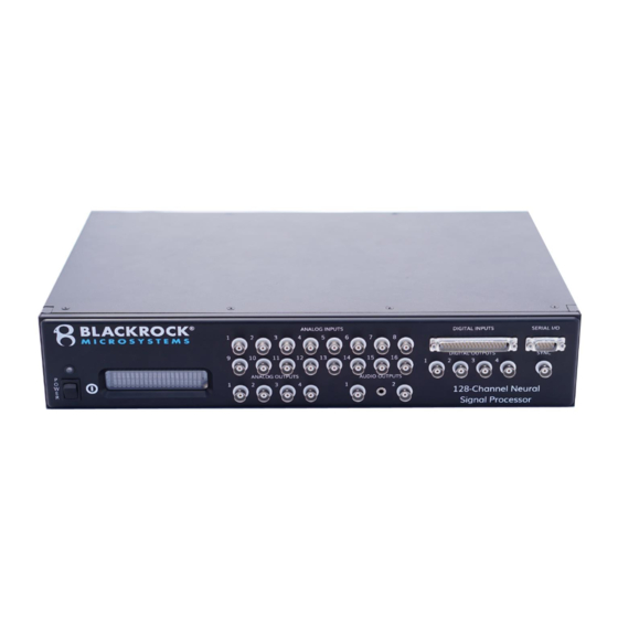
Page 13: Nsp Front Panel
±5.0 V and should come from a source impedance of less than 100 Ω. The coupling of each input channel can be manually selected in the software. By default, channels 1-8 are AC-coupled and channels 9-16 are DC-coupled. Revision 15.00 / LB-0028 – Cerebus Instructions for Use... - Page 14 A synchronization pulse can be set as an optional line to inform external equipment when the NSP neural signal inputs and front panel ports are scanned. It is active on the Revision 15.00 / LB-0028 – Cerebus Instructions for Use...
-
Page 15: Nsp Back Panel
The Fiber Optic connector is located on the front side in NSP models 1.5 and 1.0. The NSP 2.0 is equipped with an additional fiber optic input connector which enables the NSP 2.0 to communicate with more than one Front End Amplifier or Digital Hub. Revision 15.00 / LB-0028 – Cerebus Instructions for Use... - Page 16 NSP 1.75 NSP 2.0 Figure 12- Back panel view of different versions of NSP showing the adaptive Line Noise Cancellation plug (10), Synchronization Port (11), and the Fiber Optic input connector(s) (12). Revision 15.00 / LB-0028 – Cerebus Instructions for Use...
-
Page 17: Quick Setup Guide
(TCP/IPv4). Click on Internet Protocol (TCP/IP) and click on Properties For IP Address enter 192.168.137.1, for Subnet Mask enter 255.255.255.0 and leave the rest blank. Click on OK to save changes. Revision 15.00 / LB-0028 – Cerebus Instructions for Use... -
Page 18: Troubleshooting
The NSP is stuck in the initializing step. In this case, the NSP does not boot up correctly after being turned on and “Initializing Step 2” is displayed on the LCD panel. Revision 15.00 / LB-0028 – Cerebus Instructions for Use... -
Page 19: How Can I Update The Cerebus Firmware On The Nsp To The Latest Version
If that doesn’t fix the problem then the NSP must be sent back as RMA for further inspections. How can I update the Cerebus firmware on the NSP to the latest version? If your current NSP firmware which is normally displayed on the NSP's LCD panel is below version 4.00 do not perform this upgrade and contact support for more information. -
Page 20: The Front End Amplifier Power Supply Red Error Led Is On
If this happens, simply restart the power supply to see if the problem is resolved. • If the problem still not resolved, then follow the diagnostic steps mentioned in “The red error LED on the Front End Amplifier power supply” section above. Revision 15.00 / LB-0028 – Cerebus Instructions for Use... -
Page 21: The Fiber Optic Led Indicator Is Illuminating Red
This will allow users to be confident that if there is a problem they will be alerted. If the Headstage LED does not initially turn yellow/red or if the LED remains yellow/red contact Blackrock support. Revision 15.00 / LB-0028 – Cerebus Instructions for Use... -
Page 22: The Central Application Fails To Start
Check whether the NSP is powered on with the Firmware version visible on the and the ethernet settings. • Short in power path external to the supply which can be the cable, amplifier itself, headstages connected to amplifier. Revision 15.00 / LB-0028 – Cerebus Instructions for Use... -
Page 23: Warranty
Warranty Blackrock Microsystems (“Blackrock”) warrants that its products are free from defects in materials and manufacturing for a period of one year from the date of shipment. At its option, Blackrock will repair or replace any product that does not comply with this warranty. This warranty is voided by: (1) any modification or attempted modification to the product performed by anyone other than an authorized Blackrock employee;... -
Page 24: Warnings
Blackrock provided power cable to reduce the risk of electrical shock. Do not use an adapter for ungrounded wall outlets. Do not connect the Cerebus System to an outlet controlled by a wall switch. Do not use the Cerebus System in the presence of flammable anesthetic agents. -
Page 25: Symbols Of Contraindications, Warnings, Cautions
Manufactured date EN-980 Manufacturer EN-980 Warning EN-980 Batch IEC60417-5019 Protective earth (ground) IEC60417-5007 ON (power) IEC60417-5009 ON/OFF Stand-by EN-980 Serial Number EN-980 Combined Manufacturer / Manufacturing Date YEAR EN-980 Read the documentation Revision 15.00 / LB-0028 – Cerebus Instructions for Use... -
Page 26: Electromagnetic Immunity
The Cerebus System is intended for use in the electromagnetic environment specified below. The customer or the user of the Cerebus system should assure that it is used in such an environment. Guidance and manufacturer’s declaration – electromagnetic immunity – for all EQUIPMENT and SYSTEMS that are not LIFE-SUPPORTING (refer to 60601-1-2 Table 204). - Page 27 The Cerebus system is intended for use in an electromagnetic environment in which radiated RF disturbances are controlled. The customer or the user of the Cerebus system can help prevent electromagnetic interference by maintaining a minimum distance between portable and mobile RF communications equipment (transmitters) and the Cerebus system as recommended below, according to the maximum output power of the communications equipment.
Need help?
Do you have a question about the Cerebus and is the answer not in the manual?
Questions and answers