
Related Manuals for Edgetech COM.AIR


Summary of Contents for Edgetech COM.AIR
- Page 1 COM.AIR Dew Point Monitor Model COM.AIR Compressed Air Dew Point Monitor OPERATORS MANUAL Edgetech Instruments Inc. 399River Rd, Hudson, MA 01749 508-263-5900 www.edgetechinstruments.com 04/02/2015 Rev. B...
-
Page 2: Table Of Contents
COM.AIR Dew Point Monitor TABLE OF CONTENTS 1.0 GENERAL DESCRIPTION 2.0 INSTALLATION 2.1 MOUNTING 2.2 WIRING CONNECTIONS 2.3 SAMPLE CONNECTIONS 2.4 ALARM RELAY CONNECTIONS 2.5 ANALOG OUTPUT CONNECTIONS 2.6 RS-232 SERIAL 3.0 FUNCTIONAL DESCRIPTION 3.1 DISPLAY 3.2 MABC BUTTON 3.3 SILENCE ALARM BUTTON 3.4 FLOW CONTROL VALVE... - Page 3 Edgetech Instruments Inc.'s Commitment to Quality To Our Customers: Thank you for purchasing one of our products. At Edgetech Instruments, it is our policy to provide cost-effective products and support services that meet or exceed your requirements, to deliver them on time, and to continuously look for ways to improve both. We all take pride in the products we manufacture.
-
Page 4: General Description
2-1 for dimensional information. 2.2 WIRING CONNECTIONS The COM.AIR is designed to operate on AC voltages of 90 to 260 VAC with a maximum power requirement of 40 Watts. The power entrance hole, located on the bottom of the enclosure, is designed to accept a standard conduit, clamp type fitting or a compression type fitting (supplied). - Page 5 COM.AIR Dew Point Monitor 2.4 ALARM RELAY CONNECTIONS When the programmed Alarm Set Point is exceeded, the alarm relay will be energized. Before connecting any device to the Alarm Relay contacts, check the contact ratings in the Specifications section. 1. Remove the Access Panel as in Figure 2-2.
-
Page 6: Mounting
COM.AIR Dew Point Monitor FIGURE 2-1 MOUNTING 04/02/2015 Rev. B... - Page 7 COM.AIR Dew Point Monitor FIGURE 2-2 ACCESS PANEL REMOVAL 04/02/2015 Rev. B...
-
Page 8: Wiring Connections
COM.AIR Dew Point Monitor FIGURE 2-3 WIRING CONNECTIONS 04/02/2015 Rev. B... -
Page 9: Functional Description
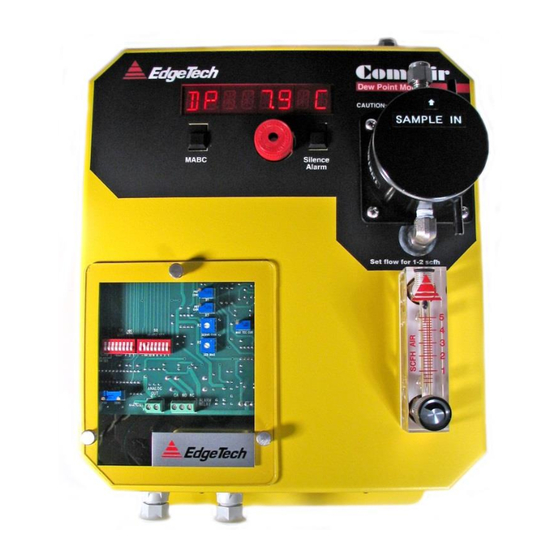
COM.AIR Dew Point Monitor 3.0 FUNCTIONAL DESCRIPTION The front panel of the COM.AIR consists of an LED Display, an audible alarm, two push-button switches, and a sample flow meter with valve. 3.1 Display The eight character alphanumeric LED display is used to display dew point data and status messages. -
Page 10: Mabc Button
-Check the sample system for proper flow. -Check for loose connections or components on the printed circuit board and sensor. If the condition cannot be resolved with these checks, contact Edgetech for service 3.2 MABC Button Pressing the MABC Button (Manual Automatic Balance Cycle) at any time will initiate an ABC Cycle. -
Page 11: Setup
COM.AIR Dew Point Monitor 4.0 SETUP 4.1 Alarm Set Point (Figure 4.1) The alarm set point temperature is set by dip switch S2 as an integer. The switch setting represents an eight bit binary number in degrees C with position 8 as the least significant bit (LSB) and position 2 as the most significant bit (MSB). - Page 12 COM.AIR Dew Point Monitor FIGURE 4-1 SETUP 04/02/2015 Rev. B...
- Page 13 COM.AIR Dew Point Monitor TABLE 4.1 SETUP BINARY BINARY -50.0 -58.0 10110010 32.0 00000000 -49.0 -56.0 10110001 33.0 00000001 -48.0 -54.0 10110000 35.0 00000010 -47.0 -52.0 10101111 37.0 00000011 -46.0 -50.0 10101110 39.0 00000100 -45.0 -49.0 10101101 41.0 00000101 -44.0 -47.0...
-
Page 14: Abc Interval
COM.AIR Dew Point Monitor 4.2 ABC Interval The ABC Interval is the time between the automatic initiation of ABC Cycles. In typical applications, an interval of 24 hours is recommended and set at the factory. However, in cases where ambient conditions are more variable, or the sample gas is higher in contaminants, a shorter interval may be required. -
Page 15: Maintenance
COM.AIR Dew Point Monitor 5.0 MAINTENANCE 5.1 ROUTINE MAINTENANCE To ensure the maximum in accurate and reliable operation of any optical chilled mirror system, a periodic maintenance program should be established. 5.2 MIRROR CLEANING SCHEDULE Over time, particulates and other matter present in the sample gas and not captured by filters, build up on the mirror. - Page 16 COM.AIR Dew Point Monitor FIGURE 5.1 SENSOR COVER REMOVED FOR MIRROR CLEANING 04/02/2015 Rev. B...
-
Page 17: Specifications
COM.AIR Dew Point Monitor 6.0 SPECIFICATIONS Measurement Range -Dew/ Frost Point -58 to 122°F(–50 to 50 °C)(Optional S2Sensor)* -103 to 167°F(–75 to 75 °C)(Optional S3Sensor)* Measurement Accuracy -Dew/ Frost Point (+0.28°C) ±0.5°F (Entire Range) Functional Power: 90-260VAC, 50-400Hz, 40 Watts...
Need help?
Do you have a question about the COM.AIR and is the answer not in the manual?
Questions and answers