Table of Contents
Advertisement
Quick Links
Download this manual
See also:
Installation Manual
Advertisement
Table of Contents
Troubleshooting

Related Manuals for Lynx NGT-9000


Summary of Contents for Lynx NGT-9000
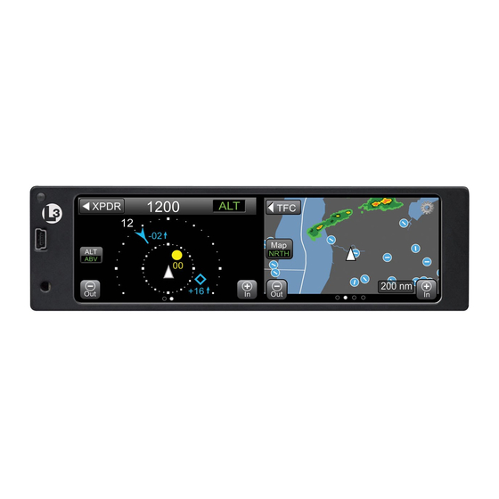
- Page 1 Pilot’s Guide for Models NGT-9000 NGT-9000R NGT-9000+ NGT-9000R+ NGT-9000D NGT-9000RD NGT-9000D+ NGT-9000RD+ Aviation Products...
- Page 3 Lynx NGT-9000. Screen information may look different on displays interfaced with the Lynx NGT-9000. Refer to the pilot’s guide for that display for a description of how information is depicted. The installation of ADS-B In avionics provides the pilot with supplemental information and does not replace a pilot’s see-and-...
- Page 4 Trademarks Lynx is a registered trademark of L-3 Avionics Systems ® The NGT-9000 is covered by one or more of the following patents: 9,285,472, 8,736,465. Other patents pending Distributed with permission by: L-3 Avionics Systems. 5353 52nd Street, S.E.
-
Page 5: Table Of Contents
Table of Contents Chapter 1: Description Introduction ....................1-1 Functional Description .................1-2 Transponder .................... 1-3 Transponder Diversity Options ............... 1-3 ADS-B System ..................1-3 Traffic Display ..................1-4 Traffic Advisory System (TAS) ..............1-4 ADS-B Traffic Advisory System (ATAS) ..........1-4 Weather Display .................. - Page 6 Table of Contents (continued) Flight ID / Call Sign ................2-10 Mode Control ..................2-10 Transponder Reply ................2-10 IDENT Button ..................2-10 Squawk VFR Button................2-11 MSG Button ...................2-11 ON-GND Indicator..................2-11 System Test Button ................2-11 Traffic Operation ..................2-13 Limitations ..................... 2-13 Traffic Advisory ..................
- Page 7 Table of Contents (continued) Automatic Dependent Surveillance – Re-broadcast (ADS-R)....2-28 Traffic Information Service - Broadcast (TIS-B) ........2-29 Traffic Advisory Systems ................2-30 ADS-B Traffic Advisory System (ATAS) ..........2-31 Traffic Advisory System (TAS) .............. 2-31 TAS Sensitivity Levels ................2-32 Sensitivity Level A ................2-32 Sensitivity Level B................2-32 Other Aircraft Ground Filtering ............2-35...
- Page 8 Table of Contents (continued) FIS-B Graphic Winds & Temp Application ..........2-49 Traffic Button ..................2-49 Aloft Button ..................2-51 Panning ....................2-51 Zoom Buttons ..................2-51 Issue Valid Time Indication ..............2-51 Ownship Symbol ................2-51 North Indicator ..................2-51 Flight Level Selection .................2-51 FIS-B Textual Application ..............2-52 Display Area ..................
- Page 9 Table of Contents (continued) TAWS Audio Alerts ................2-64 500 ft Altitude Callout.................2-64 Conditions to Trigger Alerts or Callouts..........2-65 Forward Looking Terrain Avoidance (FLTA) ........2-66 Reduced Required Terrain Clearance (RTC) ........2-67 Imminent Terrain Impact (ITI) .............2-68 Premature Descent ................2-69 Ground Proximity Warning System (GPWS) Alerting ......2-70 Excessive Descent Rate ..............2-70 Negative Climb Rate or Altitude Loss After Takeoff ......2-71...
- Page 10 Table of Contents (continued) VFR Code Select ..................3-5 Set VFR Code ..................3-5 View Info ....................3-5 Traffic Advisory Aural Acknowledge and Reply ........3-6 Enable On Ground TAS Operation ............3-6 TAWS Alert Aural Acknowledge .............. 3-6 Inhibit TAWS Alert Message ..............3-6 Inhibit TAWS Obstacles ................
- Page 11 List of Illustrations Figure 1-1: Example of Panel Mount Lynx NGT-9000 .........1-2 Figure 1-2: Example of Remote Mount Lynx NGT-9000 ......1-3 Figure 1-3: Example of Own Aircraft UAT, 1090ES, and TAS Traffic ...1-6 Figure 2-1: Example of Splash Screen ............2-2 Figure 2-2: Example of System Status / Version Screens ......2-3...
- Page 12 Table 2-9: Required Terrain Clearances for the Reduced RTC Alert Condition ..........2-68 Table 2-10: Required Terrain Clearances for the ITI Alert Condition ..2-69 Table 2-11: Lightning Symbols ..............2-76 Table 5-1: General Display Conditions for the Panel Mount Lynx NGT-9000 ..........5-1 Pilot’s Guide...
- Page 13 List Of Abbreviations and Acronyms ° Degree Advisory Circular Above ADS-B Automatic Dependant Surveillance – Broadcast ADS-R Automatic Dependant Surveillance – Rebroadcast Airplane Flight Manual Above Ground Level AIRMET Airmen’s Meteorological Information Altitude ATAS ADS-B Traffic Advisory System Air Traffic Control ATCRBS Air Traffic Control Radar Beacon System Below...
- Page 14 List Of Abbreviations And Acronyms (cont.) Mega Hertz Mode Message Multilink Surveillance System NACp Navigation Accuracy Category for Position Non Altitude Reporting National Airspace System NEXRAD Regional and Next-Generation Radar Navigation Integrity Category NOTAM Notices to Airmen NM or nmi Nautical Miles Normal Other Traffic Proximity Advisory...
-
Page 15: Chapter 1: Description
CHAPTER 1 DESCRIPTION INTRODUCTION The Lynx NGT-9000 family of products are a Mode S Level 2 dens Class 1 Transponder with an integrated GPS receiver providing Automatic Dependent Surveillance-Broadcast (ADS-B) output using 1090ES (Extended Squitter). The Lynx NGT-9000 also receive ADS-B data via 1090ES and UAT (978 MHz Universal Access Transceiver). -
Page 16: Functional Description
Description Lynx NGT-9000 ® FUNCTIONAL DESCRIPTION The panel mount versions of the Lynx NGT-9000 can display and control the following information: • Built-In Test and Operational Status • Transponder Functions • Traffic and Weather Output Interfaces • Diversity (optional, model specific) •... -
Page 17: Transponder
Figure 1-2: Example of Remote Mount Lynx NGT-9000 Transponder The transponder function of the Lynx NGT-9000 replies to Mode A, Mode C and Mode S interrogations on 1030 MHz and transmitting responses at 1090 MHz. Transponder operation is performed on the left application screen. -
Page 18: Traffic Display
Traffic Advisory System (TAS) The Traffic Advisory System (TAS) is an optional feature of the Lynx NGT-9000. This feature provides the capability to interrogate nearby aircraft transponders and issue Traffic Advisory (TA) alert as well as a voice audio output that announces Traffic Advisories and relative altitude to the flight crew. -
Page 19: Weather Display
Release 2.1 or greater. Lightning Detection is an optional function provided by the interface of a WX-500 Stormscope. This information is shown on the right application screen of the NGT-9000 Panel Mount unit. This function is not available for the NGT-9000R Remote Mount version. -
Page 20: Figure 1-3: Example Of Own Aircraft Uat, 1090Es, And Tas Traffic
Description Lynx NGT-9000 ® 70 nm ( Other Aircraft 1090ES 30 nm ( TIS-B ADS-R Other Aircraft Own Aircraft 1090ES TAS (model option) ADS-R Other Aircraft TIS-B FIS-B Other Aircraft UAT Non-Equipped Mode A/C Equipped TIS-B ATC - Ground Station Figure 1-3: Example of Own Aircraft UAT, 1090ES, and TAS Traffic Pilot’s Guide... -
Page 21: Equipment Description
Description ® EQUIPMENT DESCRIPTION The Lynx NGT-9000 MSS family consists of the following standard and optional equipment. Refer to the Aircraft Flight Manual Supplement to determine what optional equipment is installed. Chapter 5 provides a list of optional cockpit switches and lamps. -
Page 22: Directional Antenna
L-3 Avionics Systems for a current list of compatible applications. WiFi Serial Adapter The Lynx NGT-9000 can be connect to a PED via WiFi using a compatible WiFi Serial Adapter. CP-2500 Control Panel The CP-2500 is a control panel offered by L-3 Avionics Systems for operation of the remote mount Lynx NGT-9000R. -
Page 23: Chapter 2: Operation - Panel Mount
OPERATION - PANEL MOUNT INTRODUCTION This chapter describes the operation of the Panel Mount version of the Lynx NGT-9000. Details on the optional cockpit switches and indicator lamps are provided in chapter 3. PILOT ADVISORY The display of ADS-B data only supplements and does not replace any operational procedure. -
Page 24: Power On
It may be placed in standby only if the system is inoperable or if advised by ATC to disable ADS-B. • Loss of input data may not cause the NGT-9000 to fail but could degrade operation. Failure and degraded conditions will be annunciated by the NGT-9000 to alert the pilot to the operational status. -
Page 25: System Status / Versions Screen
Lynx NGT-9000 Operation - Panel Mount ® System Status / Versions Screen The system status is shown on the left screen and should show “System Pass” in green text along with an audio indication of “System Test Passed”. The version screen is located on the right side and shows the software and database version information. -
Page 26: Flight Id Screen (Optional)
Operation - Panel Mount Lynx NGT-9000 ® Flight ID Screen (optional) The Flight ID Screen is a configuration option that must be setup during installation. Most general aviation aircraft will be operated in a manner that does not require Flight ID. See Figure 2-3. It is shown after the System Status/Version Screen and shows the following information: •... -
Page 27: Basic Operation
Lynx NGT-9000 Operation - Panel Mount ® BASIC OPERATION The touch screen display is divided into left and right screens that show information specific to the selected application. The user can select, input, and adjust information on the screen using buttons, edit boxes and screen objects using gestures (actions) such as tap, momentary press, drag, or swipe. - Page 28 Operation - Panel Mount Lynx NGT-9000 ® Table 2-1: Button Functions (continued) NAME - FUNCTION EXAMPLE Radio Button: The radio button is used to control related functions of which Above Above only one may be active. The circular Not Selected - Selected...
-
Page 29: Application Screens
Lynx NGT-9000 Operation - Panel Mount ® Table 2-1: Button Functions (continued) NAME - FUNCTION EXAMPLE Selection List: Selection Lists are used where there is a list of items from which a selection can be made. A green filled circle is shown when an item is selected. - Page 30 Operation - Panel Mount Lynx NGT-9000 ® Right Screen The right screen has between two and six application indicators. The number of indicators is dependent on the feature enablement. The two screens that are always available are the Traffic and the FIS-B Graphical Data Screen.
-
Page 31: Transponder Operation
Lynx NGT-9000 Operation - Panel Mount ® TRANSPONDER OPERATION The transponder receives interrogations from surrounding aircraft and from ATC and then transmits replies. Ground stations can interrogate Mode S Transponders individually using a 24-bit ICAO Mode S address, which is unique to the particular aircraft. -
Page 32: Current Pressure Altitude
Operation - Panel Mount Lynx NGT-9000 ® Current Pressure Altitude The current pressure altitude (PALT) is located below the Squawk Code. A value greater than 99,900 ft will set the value to 99900 with amber text. An invalid pressure altitude is shown as amber dashes. -
Page 33: Squawk Vfr Button
Lynx NGT-9000 Operation - Panel Mount ® Squawk VFR Button Tap the Squawk VFR toggle button to change the transponder squawk code to a predefined (1200) VFR value. The value shown on the button is the code that is activated when the button is tapped. A second press reverts the transponder to the previous squawk code. -
Page 34: Figure 2-7: Example Of System Test Screen
Operation - Panel Mount Lynx NGT-9000 ® System Status Self Test In Progress ADS-B In: Pass ADS-B Out: Pass Transponder: Pass FIS-B: Fail TAS: Pass ATAS: Pass TAWS: Degraded Figure 2-7: Example of System Test Screen The left screen shows the system affect of the tests results on the functional areas of the system. -
Page 35: Traffic Operation
ATAS and TAS may operate at the same time with traffic information being correlated by the Lynx NGT-9000. Details on these features are shown on page “Traffic Advisory Systems”... -
Page 36: Traffic Screen
Operation - Panel Mount Lynx NGT-9000 ® Traffic Screen The traffic screen has a black background. Transponder Mode can be set to Standby (SBY), On (ON), or Altitude (ALT). The Traffic application is available on both the left and right screen. -
Page 37: Ownship Symbol
(A semi-circle at the edge of the display represents an off-scale TA). • Units with the optional TAS feature (e.g., NGT-9000+ or NGT- 9000R+) display traffic advisory symbols and output aural TA warnings (Release 1 “traffic, traffic” or Release 2.0 or greater “Traffic”... - Page 38 Operation - Panel Mount Lynx NGT-9000 ® • A velocity vector arrow may be appended to the right side of a traffic symbol to indicate that the intruder aircraft is ascending (up arrow) or descending (down arrow) faster than 500 fpm. No arrow is shown for intruder aircraft in level flight, or for those moving vertically slower than ±500 fpm, or for non-altitude-reporting...
-
Page 39: Table 2-2: Traffic Symbols
Lynx NGT-9000 Operation - Panel Mount ® Table 2-2: Traffic Symbols SYMBOL DESCRIPTION - EXAMPLE Airborne Directional Traffic Advisory (TA) (TAS or ATAS option only) Airborne Directional Proximity Advisory (PA) * Airborne Directional Other Traffic (OT) * (Panel mount only) -
Page 40: Traffic Display Priority
Operation - Panel Mount Lynx NGT-9000 ® Traffic Display Priority When multiple intruders are displayed, some overlapping of symbols and/or data may occur. In these instances, the intruder with the greatest threat partially or completely overlaps the intruders that pose lower threats. -
Page 41: Zoom Buttons
Lynx NGT-9000 Operation - Panel Mount ® Zoom Buttons Zoom In (+) and Zoom Out (-) buttons are located on the bottom of each traffic screens. The buttons are used to change the traffic display range. Range Rings The range rings are oriented around the ownship. A range indicator is located outside the upper left corner of the outer most ring. -
Page 42: Transponder Banner
An amber “XPDR Failed” is shown when the transponder function has failed. Traffic Mode Indicator The Traffic Mode Indicator is available only when a Lynx NGT-9000 with TAS is installed. Otherwise the “ADS Only” is assumed to be operating for non-TAS installs. -
Page 43: Traffic Options Screen
Lynx NGT-9000 Operation - Panel Mount ® Traffic Options Screen Two latch buttons and a done button are located on the bottom. The Status button opens a screen showing GPS satellite information. The Settings button opens a screen allowing the setting of Initial Traffic Altitude Mode, VFR Squawk Code, Display Brightness Trim, and Flight ID (if configured). -
Page 44: Options - Settings
Operation - Panel Mount Lynx NGT-9000 ® • “Error” - SVERROR (trying to exclude) [Fault detection detects a position failure which cannot be excluded within the time-to- alert when integrity is being provided by FDE] • SIL: This value is always 3. Displayed GPS Satellite information is shown as horizontal bars in increasing numerical order. -
Page 45: Acknowledge Button
ADS-R data is not available in the area (i.e. out of range of a ADS-B ground station). • The indicator is also shown if a problem exists with the NGT-9000 System. See the troubleshooting section. • The indicator will not be shown when TAS (if installed) is operational (i.e. -
Page 46: Traffic Information Window
Operation - Panel Mount Lynx NGT-9000 ® Traffic Information Window The window is shown over the traffic screen and provides the following data and functionality: • Flight ID of the selected aircraft. • Emitter Category or “type” of aircraft. • An aircraft Icon is located on the right side of the window showing a representation of the aircraft being tracked. -
Page 47: Selected Traffic Gs
Lynx NGT-9000 Operation - Panel Mount ® Selected Traffic GS The Selected Traffic GS (if configured) is located along the right side of both screens (under the selected traffic ID) after a traffic symbol is pressed. The Traffic GS is removed when the selected traffic symbol is tapped, a Traffic Advisory (TA) occurs, or if the selected traffic is no longer being tracked. -
Page 48: Extended Audio Callouts
Operation - Panel Mount Lynx NGT-9000 ® Extended Audio Callouts The Extended Audio Callouts is a configuration option that adds relative bearing, relative altitude (when available) and range to the intruder information announced as well as the normal alert (or relative altitude, range, and vertical sense for Release 2.0 or greater) It is... -
Page 49: Details On Traffic Operation
NGT-9000 Operation - Panel Mount ® • (Release 2.0 or greater) Tap the Acknowledge Button on the Lynx NGT-9000 traffic display to cancel the current aural announcement. • (Release 2.1 or greater) Configuration Options “TAS Ground Filtering”: (1-standard) Aural traffic alerts from TAS functions are suppressed when ownship is below 380ft AGL (above ground level). -
Page 50: Automatic Dependent Surveillance - Re-Broadcast (Ads-R)
Operation - Panel Mount Lynx NGT-9000 ® Automatic Dependent Surveillance – Re-broadcast (ADS-R) ADS-R is a ground based broadcast service that repeats ADS-B messages from one link (1090 MHz or 978 MHz) to the other link for aircraft with ADS-B In. -
Page 51: Traffic Information Service - Broadcast (Tis-B)
Lynx NGT-9000 Operation - Panel Mount ® Traffic Information Service - Broadcast (TIS-B) TIS-B is the broadcast from Ground Radio Stations of ATC derived traffic information to ADS-B equipped aircraft. • The actual availability of TIS-B source data depends upon the availability of ground-based radar. -
Page 52: Traffic Advisory Systems
The Lynx NGT-9000 has two traffic advisory systems available. • The Traffic Advisory System (TAS) option requires a specific model of the Lynx NGT-9000. TAS is an active system that interrogates nearby aircraft transponders. • The ADS-B Traffic Advisory System (ATAS) option provides traffic alerts using ADS-B In (ADS-B, ADS-R, and TIS-B) traffic information. -
Page 53: Traffic Advisory System (Tas)
When replies to these active interrogations are received, the responding aircraft’s range, altitude, and closure rates are computed to plot traffic location and predict collision threats. The NGT-9000+ or NGT-9000R+ alerts the flight crew to nearby transponder equipped aircraft and assists the pilot in the visual acquisition of aircraft that may represent a danger. -
Page 54: Tas Sensitivity Levels
Operation - Panel Mount Lynx NGT-9000 ® TAS Sensitivity Levels The A or B sensitivity level is used to determine when to display a TA. Having two sensitivity levels allows the unit to reduce the number of nuisance TAs during takeoff and landing (sensitivity level A), and to maximize the detection of TAs during the cruise phase of flight (sensitivity level B). -
Page 55: Table 2-3: Tas Traffic Advisory Situations
Lynx NGT-9000 Operation - Panel Mount ® Table 2-3: TAS Traffic Advisory Situations OWN SHIP OTHER AIRCRAFT IS SHIP ALT GND SPEED DETECTED Within a 0.2 nmi horizontal radius and a +/- 600 ft relative Below altitude. 2000 ft Within 15-20 sec of CPA * Within a 0.55 nmi horizontal... -
Page 56: Figure 2-12: Traffic Display Mode And Tas Traffic Zone Graphic
Operation - Panel Mount Lynx NGT-9000 ® Not To Scale Up to 35 nmi +9900ft Up to 35 nmi +9000 ft Up to 35 nmi +2700 ft 4 nmi +1200 ft 0.55 nmi +800 ft 0.2 nmi +600 ft TAS Sensitivity Level A *... -
Page 57: Other Aircraft Ground Filtering
ADS-B reporting traffic will be received. It also does not limit the range at which the Lynx NGT-9000 ADS-B output will be received by other aircraft. 3. Dual TAS/ATAS operation where aircraft tracked by both alerting systems will alert based on the ATAS system. -
Page 58: Weather Operation
Operation - Panel Mount Lynx NGT-9000 ® WEATHER OPERATION The Lynx NGT-9000 provides weather information using data provided Flight Information Service - Broadcast (FIS-B). by the The FIS-B service is available only from a ground station that is in range to aircraft equipped with UAT receivers. -
Page 59: Table 2-4: Description Of Fis-B Available Information
Lynx NGT-9000 Operation - Panel Mount ® Table 2-4: Description of FIS-B Available Information PRODUCT DESCRIPTION AIRMET Text/graphical report - Airmen’s Meteorological Infor- mation is a weather advisory issued by a meteoro- logical watch office a potentially hazardous condition exists for low-level aircraft and/or aircraft with limited capability. - Page 60 Operation - Panel Mount Lynx NGT-9000 ® Table 2-4: Description of FIS-B Available Information (continued) PRODUCT DESCRIPTION SIGMET Text/graphical report − Potentially hazardous en route phenomena such as thunderstorms and hail, turbulence, icing, sand and dust storms, tropical cy- clones, and volcanic ash in an area affecting 3,000 square miles or an area deemed to have a significant effect on safety of aircraft operations.
-
Page 61: Fis-B No Coverage Indicator
(i.e. out of range of a ADS-B ground station). • The indicator is also shown if a problem exists with the NGT-9000 System. See the troubleshooting section. When configured to be disabled, the Winds & Temps and FIS-B textual data screens are deactivated and the FIS-B No Coverage Indicator is disabled. -
Page 62: Fis-B Graphical Weather Application
Operation - Panel Mount Lynx NGT-9000 ® FIS-B Graphical Weather Application The Graphical Weather Application is located in the second screen position (or third screen position when TAWS is enabled, Release 2.0 or greater) as indicated by the Application Indicator. The Graphic... -
Page 63: Information Button (I)
Lynx NGT-9000 Operation - Panel Mount ® • The land masses are black. Bodies of water are dark blue. Depiction of NEXRAD weather radar data is overlaid on the map. Map areas where NEXRAD data has not been received are indicated using a gray semi-transparent graphical overlay. -
Page 64: Table 2-5: Airport Symbols
Operation - Panel Mount Lynx NGT-9000 ® Table 2-5: Airport Symbols DESCRIPTION SYMBOL Towered Soft Surfaced Airport Non-towered Soft Surfaced Airports Towered Hard Surfaced Small Airports (1,500 to 8,069 ft runway) Non-towered Hard Surfaced Small Airports (1,500 to 8,069 ft runway) Towered Hard Surfaced Large Airports (>... -
Page 65: Metar
Lynx NGT-9000 Operation - Panel Mount ® METAR METAR is a report of weather conditions at airports represented graphically and consists of the FAA Flight Rules and Weather Conditions. The flight rules icons shows the FAA flight rules for each airport based on the visibility and cloud cover conditions. -
Page 66: Traffic Button
Operation - Panel Mount Lynx NGT-9000 ® Traffic Button This button is located on the far left side of the screen and is labeled “TFC” with a left facing triangle. Tap the button to return to the Traffic Application screen. -
Page 67: Map Options Button
Lynx NGT-9000 Operation - Panel Mount ® Map Options Button The gear shaped Options Button is located in the upper right corner of the map screen. Tapping the button opens the Options screen that has three latch buttons located on the bottom of the screen. These buttons are labeled ON/OFF, Declutter, and Done. -
Page 68: Figure 2-17: Weather Map Legend Screen
Operation - Panel Mount Lynx NGT-9000 ® Figure 2-17: Weather Map Legend Screen 2-46 Pilot’s Guide... -
Page 69: Display Area
Lynx NGT-9000 Operation - Panel Mount ® Display Area The left display area is used to show the meaning of map elements provided by FIS-B products. It is identified with the label “Legend”. A scroll bar on the right side provides an indication that additional information can be seen by using an up/down drag action. -
Page 70: Display Area
Operation - Panel Mount Lynx NGT-9000 ® Time: 19 June 18:54 UTC Wind: From 320 at 04KT Gusts: None Visibility: 10 Mile Weather: No significant weather Ceiling: 100000 ft AGL Figure 2-19: Weather Map Text Screen Display Area The left display area is used to show text report data from the selected map element. -
Page 71: Fis-B Graphic Winds & Temp Application
Lynx NGT-9000 Operation - Panel Mount ® Figure 2-20: Product Pick List Window FIS-B Graphic Winds & Temp Application The Graphical Winds and Temperature Application is available on the right screen and is located in the third screen position (4th screen position when TAWS installed, Release 2.0 or greater) as indicated... -
Page 72: Figure 2-22: Winds Aloft Map Elements
Operation - Panel Mount Lynx NGT-9000 ® The winds aloft display properties are defined in Figure 2-22. Figure 2-22: Winds Aloft Map Elements 2-50 Pilot’s Guide... -
Page 73: Aloft Button
Lynx NGT-9000 Operation - Panel Mount ® Aloft Button This button is located on the left side of the screen and is labeled “Aloft” with white text and the active selection labeled either “Wind” or “Temp” with green text. Tap the button to select the other screen function. -
Page 74: Fis-B Textual Application
Operation - Panel Mount Lynx NGT-9000 ® FIS-B Textual Application The Textual Application is available on the right screen and is located in the fourth screen position as indicated by the Application Indicator. This application screen displays textual weather information products for selected airports provided by FIS-B. -
Page 75: Airport Button
Lynx NGT-9000 Operation - Panel Mount ® Airport Button This button is located to the right of the Traffic button is labeled with the Selected Airport identifier. This information is also shown below in the display area. Tap the button to open the Edit Airport ID window. -
Page 76: Favorites Button
Operation - Panel Mount Lynx NGT-9000 ® Favorites Button This button is labeled with a amber star icon. Tap the button to open the Favorites Pick List window. Favorites Pick List Window This window is used to select a pre-saved Airport ID. See Figure 2-25. -
Page 77: Product Button
Lynx NGT-9000 Operation - Panel Mount ® Product Button This button is labeled with the current selected product. Tap the button to open the Product Pick List window. Product Pick List Window This window is used to select an available FIS-B Textual Product, which are METAR, NOTAM , and TAF. -
Page 78: Taws Operation
The details for the TAWS Screen at the beginning of this section is for the Panel Mount version of the Lynx NGT-9000. The instructions for TAWS Audio Alerts (page 2-64) and Conditions to Trigger Alerts or Callouts (page 2-65 to page 2-73) are for both the Panel and Remote Mount versions of the Lynx NGT-9000. -
Page 79: Limitations
Lynx NGT-9000 Operation - Panel Mount ® Limitations • The TAWS function shall not be used as a navigation instrument. It is not intended to provide navigational guidance nor to relieve pilots from following published navigational procedures, routes, altitude restrictions, and/or instructions from air traffic control agencies except in response to alerts to avoid potentially hazardous terrain and/or obstacles. -
Page 80: Display Range Indicator
Operation - Panel Mount Lynx NGT-9000 ® Display Range Indicator This indication is a readout of the selected display range and is located in the lower right corner of the display. Display Orientation Indicator The display orientation indicator is located on the lower left side of the... -
Page 81: Ownship Symbol
Lynx NGT-9000 Operation - Panel Mount ® Ownship Symbol The ownship symbol is a white triangle when the display orientation is direction-up (true heading or true track-up are valid) and is centered horizontally, but moved down to the lower one third of the screen. An ownship velocity vector line uses ownship track and ground speed to indicate 30 seconds of ownship travel. -
Page 82: Airport Symbols
Operation - Panel Mount Lynx NGT-9000 ® Airport Symbols The symbol for the different types of airports are described in Table 2-5. Airport symbols are shown on the screen when the display range is 12 nmi or less. Airport Symbol Operation Tap the symbol to display the Airport Identifier and the Information button on the right side of the screen. -
Page 83: Taws Terrain Color Legend
Lynx NGT-9000 Operation - Panel Mount ® The TAWS system has a predictive terrain alert “or quiet zone” around each airport runway to help reduce nuisance alerts during a normal takeoff or landing procedures. GPWS-type alerts such as ‘excessive descent rate’, however, are still active and will alert in this area. -
Page 84: Information Button (I)
Operation - Panel Mount Lynx NGT-9000 ® Information Button (i) The Information button is shown on the screen, located on the right side of the screen, after a airport symbol is selected. The button is gray in color and labeled with an “i” icon. Tap the button to show the TAWS Airport screen on the left side of the screen. -
Page 85: Taws Options Button
Lynx NGT-9000 Operation - Panel Mount ® TAWS Options Button The gear shaped Options Button is located in the upper right corner of the right application screen. Tap the button to open the options screen. Refer to Figure 2-29. Figure 2-29: TAWS Options Screen... -
Page 86: Taws Audio Alerts
Operation - Panel Mount Lynx NGT-9000 ® Table 2-7: TAWS Display Alerts TAWS Warning Symbol TAWS Caution Symbol TAWS Warning Text TAWS Caution Text TAWS Caution Obstacle Text TAWS Inhibited TAWS Audio Alerts Aural announcements for caution alerts are repeated every 7 seconds and require immediate flight crew awareness and possible action. -
Page 87: Conditions To Trigger Alerts Or Callouts
Lynx NGT-9000 Controls and Indicators ® Table 2-8: Caution & Warning Alert Phrases* Warning CAUTION Alert ALERT ALERT Phrases CONDITION PHRASES Reduced “Caution, Terrain; “Terrain, Terrain; Caution, Terrain!” Pull Up, Pull Up!” Required Terrain Clearance (RTC) (Figure 2-32) “Caution, Obstacle;... -
Page 88: Forward Looking Terrain Avoidance (Flta)
Controls and Indicators Lynx NGT-9000 ® Forward Looking Terrain Avoidance (FLTA) The conditions, reduced required terrain clearance and imminent terrain impact, are part of the TAWS FLTA function. Using FLTA, TAWS looks ahead of the airplane (in the database) along its projected vertical and horizontal flight path, including turns, to determine if any terrain or obstacles might pose a threat (Figure 2-30). -
Page 89: Reduced Required Terrain Clearance (Rtc)
Lynx NGT-9000 Operation - Panel Mount ® Reduced Required Terrain Clearance (RTC) The reduced RTC alert condition (Figure 2-32) occurs when the aircraft is currently above the altitude of the upcoming terrain along the projected flight path, but the projected terrain clearance is less than the required terrain clearance (Table 2-9). -
Page 90: Imminent Terrain Impact (Iti)
Operation - Panel Mount Lynx NGT-9000 ® Imminent Terrain Impact (ITI) The ITI alert condition (Figure 2-33) occurs when your aircraft is currently below the altitude of the upcoming terrain along the projected flight path, and the projected terrain clearance is less than the required terrain clearance (Table 2-10). -
Page 91: Premature Descent
Lynx NGT-9000 Operation - Panel Mount ® Premature Descent The premature descent alert condition (Figure 2-34) occurs when your aircraft is significantly below the normal final approach flight path to the nearest runway (typically a 3-degree implied glideslope). This condition may exist for a variety of reasons such as poor visibility or nighttime operation. -
Page 92: Ground Proximity Warning System (Gpws) Alerting
Operation - Panel Mount Lynx NGT-9000 ® Ground Proximity Warning System (GPWS) Alerting The alert and callout conditions for excessive descent rate, negative climb rate or altitude loss after takeoff, and altitude of 500 ft are determined by the TAWS function subtracting the terrain elevation stored in its terrain database from the GPS-based aircraft altitude to calculate height above terrain. -
Page 93: Negative Climb Rate Or Altitude Loss After Takeoff
Lynx NGT-9000 Operation - Panel Mount ® Negative Climb Rate or Altitude Loss After Takeoff These alert conditions (Figure 2-37), also known as GPWS Modes 3A and 3B are enabled between 50 and 700 ft above the runway after takeoff or after a missed approach. The negative climb rate alert condition is based on descent rate. -
Page 94: Figure 2-38 Negative Climb Rate Graph
Operation - Panel Mount Lynx NGT-9000 ® When the aircraft’s height above the runway elevation and its descent rate or altitude loss fall within the envelopes shown in figures 2-38 and 2-39, TAWS issues a caution alert. Caution Alert: “Don’t sink!”... -
Page 95: Altitude Of 500 Ft
Lynx NGT-9000 Operation - Panel Mount ® Altitude of 500 ft This condition (Figure 2-40), also known as a subset of GPWS Mode 6, occurs when the aircraft descends within 500 ft of the terrain during enroute mode, or when the aircraft is in enroute mode in level flight but the terrain below rises up within 500 ft of the aircraft. -
Page 96: Lightning Operation
Operation - Panel Mount Lynx NGT-9000 ® LIGHTNING OPERATION Lightning detection is an optional function that is set up during installation. The Lightning function continuously monitors electrical discharges from thunderstorms within a 200 nmi radius of the aircraft and plots the location of the discharges as cells or strikes on the right application screen. -
Page 97: Ownship Symbol
Lynx NGT-9000 Operation - Panel Mount ® Figure 2-42: Lightning Screen 120 View Ownship Symbol The ownship symbol is a white triangle with the nose of the ownship symbol corresponding to the ownship position. • When the View mode is 360 the symbol is centered on the screen. -
Page 98: Mode Button
Operation - Panel Mount Lynx NGT-9000 ® Mode Button This toggle button is located on the left side of the screen and is labeled “MOD”. The button has two selections “STK (strike) and “CEL” (cell). The lower half of the button shows the current mode selection in green text. -
Page 99: Lightning Option Button
Lynx NGT-9000 Operation - Panel Mount ® Lightning Options Button The gear shaped Options Button is located in the upper right corner of the right application screen. Tap the button to open the Lighting Setting page. Refer to Figure 2-43. -
Page 100: Heading Stabilization
Operation - Panel Mount Lynx NGT-9000 ® Heading Stabilization The heading stabilization automatically adjusts the position of the discharge points on the screen when the aircraft changes heading. • This feature is not available for aircraft with out a heading input or if heading data is invalid. -
Page 101: Maintenance Mode
Maintenance mode is used to perform a screen calibration. See Figure 2-44. 1. Apply power to the Lynx NGT-9000. 2. When the splash screen is shown press and hold (continue holding when the status and version screens are showing) in the lower left corner of the display until the Activate Maintenance Mode window is shown on the right screen. - Page 102 Operation - Panel Mount Lynx NGT-9000 ® Activate Maintenance Mode? Maintenance Screen Calibration > Reboot > Touch and Release Target Reboot < Back Main App > Maint No-WiFi > Maint With-WiFi > Ground Test > Figure 2-44: Maintenance Screens 2-80...
-
Page 103: Chapter 3: Operation - Remote Mount
4. POWER ON 1. There is no power on/off switch for the Remote Mount Lynx NGT- 9000R. Depending on the aircraft, use either the battery switch or avionics master switch to apply power. Normal operation begins within 20 seconds of applying power. -
Page 104: Cp-2500 Control Panel
The following optional functions are part of the configuration options set during installation of the Lynx NGT-9000R: set a flight ID mode, Traffic functions, and TAWS functions. In addition pressing the I button activates the IDENT, pressing the V... -
Page 105: Power Off
To remove power to the CP-2500, press and hold the small knob button until the message “Power Down” is shown on the display. (Note - This does not remove power to the Lynx NGT-9000R.) Enter the Squawk Code 1. Rotate the large knob to select the squawk page. -
Page 106: View Pressure Altitude
Set Flight ID The flight ID function is optional and is part of the configuration options set during installation of the NGT-9000. 1. Rotate the large knob to select ID. 2. Press the small knob to select the first digit. -
Page 107: Set Vfr Code
Lynx NGT-9000 Operation - Remote Mount ® Set VFR Code The VFR code can be changed from the default (always set to 1200 in the United States). 1. Press the M (Menu) button. 2. Rotate the large knob to scroll the menu to VFR 3. -
Page 108: Enable On Ground Tas Operation
Operation - Remote Mount Lynx NGT-9000 ® Enable On Ground TAS Operation This function is a configuration option. The TAS On Ground Setting is available only when the aircraft status is “On Ground”. 1. Press the M (Menu) button. 2. Rotate the large knob to scroll the menu to “TRAF”. -
Page 109: Inhibit Taws Obstacles
“NO LRU RESPONSE”, “XPDR FAIL”, “ADS-B OUT FAIL”, “ADS-B IN FAIL”, “FIS-B FAIL”, “GPS FAIL”, “TAS FAIL”, “TAWS FAIL”. Note - Release 1 of the NGT-9000 does not show the fail message. • If a degraded condition is detected a degraded message is flashed on the CP-2500 screen for 5 seconds. -
Page 110: Display Messages
• NO LRU RESPONSE: The CP-2500 has detected loss of communication with the Lynx NGT-9000R. • GPS FAIL: The GPS derived position input is not functioning. • GPS INIT: GPS Initialization –The GPS contained within the Lynx NGT-9000R is not ready. Pilot’s Guide... - Page 111 • ADS-B OUT FAIL: The ADS-B out is not being transmitted by the Lynx NGT-9000R due to the GPS position not being available for more than 2 minutes, or possibly a failure of the Lynx NGT- 9000R. • ADS-B OUT DEGRADED: The ADS-B out function is operating in a degraded condition.
- Page 112 Controls and Indicators Lynx NGT-9000 ® Page intentionally blank 3-10 Pilot’s Guide...
-
Page 113: Chapter 4: Controls And Indicators
This switch activates SPI and transmits an ident pulse. An ident pulse highlights the aircraft’s symbol on the ATC’s radar screen and is identified on the panel mount Lynx NGT-9000 screen when active. Audio Acknowledge Release 2.0 or greater. This button cancels the current aural alert. -
Page 114: Indicator Lamps
• A Self-test is active, the lamp will be “ON” for approximately 8-10 seconds. ADS-B Out Fail The ADS-B Out Fail lamp primarily indicates when the Lynx NGT-9000 is not providing ADS-B output data. The lamp may be illuminated (ON) for any of the following reasons: 1. -
Page 115: Alternate Displays
(see 4c above). ALTERNATE DISPLAYS An alternate display may be interfaced to the Lynx NGT-9000, but care must be taken to insure that there is not a conflict of input commands. Use the following guidelines when using an alternate display: •... -
Page 116: Other Traffic Symbol
Off-Scale Traffic Advisory (TA) This function is limited to Lynx NGT-9000 with TAS or ATAS enabled. The Off-Scale Traffic Advisory symbol (amber on color alternate displays) represents a TA that has been detected beyond the current display range. -
Page 117: Weather Display
Refer to the displays operations manual for details on operation and a description of how the weather is depicted. WiFi Interface The Lynx NGT-9000 provides the following report messages to the Personal Electronic Device (PED) via RS-232: • Ownship Report •... - Page 118 Controls and Indicators Lynx NGT-9000 ® Page intentionally blank Pilot’s Guide...
-
Page 119: Chapter 5: Troubleshooting
TROUBLESHOOTING INTRODUCTION This chapter describes potential conditions that could occur while using the Lynx NGT-9000 MultiLink Surveillance System. Installations using a display for traffic or weather should also refer to that products Pilot’s Guide for troubleshooting information. It is recommended to crosscheck other cockpit displays/instruments for errors and/or data inconsistency. -
Page 120: Troubleshooting
Troubleshooting Lynx NGT-9000 ® Table 5-1: General Display Conditions for the Panel Mount Lynx NGT-9000 INDICATION DESCRIPTION Traffic Unavailable • ADS-B is operational but heading and track are invalid. (Amber text) • GPS is failed. • TAS is in Standby. - Page 121 Lynx NGT-9000 Troubleshooting ® Table 5-1: General Display Conditions for the Panel Mount Lynx NGT-9000 INDICATION DESCRIPTION TAWS Unavailable The indication is shown when GPS is not providing enough data for the (White text) TAWS system to work or terrain data is Release 2.0 or greater...
-
Page 122: System Status Messages
System Test button is pressed. The typical meanings of the messages are detailed in the bullets below. • A “Fail” message is caused by something internal to the Lynx NGT- 9000. • An “External Fail” message is caused by a problem with the external equipment input signals. -
Page 123: Record Of Important Information
APPENDIX A RECORD OF IMPORTANT INFORMATION Dealer Information Name ____________________________________________ Address __________________________________________ City, State, Zip _____________________________________ Telephone ____________________________________________ Equipment Information Date of Purchase ___________________________________ Installation Date ____________________________________ Model Number _____________________________________ Part Number ______________________________________ Serial Number _____________________________________ Mod Letter ________________________________________ Software Release ___________________________________ Aircraft Information Aircraft Make ______________________________________ Aircraft Model ______________________________________... - Page 124 Aviation Products 0040-17000-01 Revision H (November 7, 2016)
Need help?
Do you have a question about the NGT-9000 and is the answer not in the manual?
Questions and answers