Table of Contents
Advertisement
Quick Links
OPERATOR'S MANUAL
HWH COMPUTER-CONTROLLED
725 SERIES LEVELING SYSTEM
Single Touch - Touch Panel Leveling Control
Ph: 800/321-3494 (or) 563/724-3396 | Fax: 563/724-3408
AP54451
H H
W
CORPORATION
R
FEATURING:
BI-AXIS Hydraulic Leveling
R
Four Power-Extend/Power-Retract Jacks
Manual Pilot Air Dump
Auxiliary Hand Pump
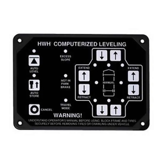
HWH COMPUTERIZED LEVELING
R
EXCESS
SLOPE
AUTO
LEVEL
NOT IN
PARK/
BRAKE
AUTO
STORE
TRAVEL
MODE
CANCEL
WARNING!
UNDERSTAND OPERATOR'S MANUAL BEFORE USING. BLOCK FRAME AND TIRES
SECURELY BEFORE REMOVING TIRES OR CRAWLING UNDER VEHICLE.
HWH CORPORATION
(On I-80, Exit 267 South)
2096 Moscow Road | Moscow, Iowa 52760
www.hwh.com
R
EXTEND
EXTEND
MANUAL
RETRACT
RETRACT
ML54452/MP04.3460
22OCT14
Advertisement
Table of Contents

Related Manuals for HWH Corporation 625S Series


Summary of Contents for HWH Corporation 625S Series
- Page 1 CANCEL WARNING! UNDERSTAND OPERATOR’S MANUAL BEFORE USING. BLOCK FRAME AND TIRES SECURELY BEFORE REMOVING TIRES OR CRAWLING UNDER VEHICLE. HWH CORPORATION (On I-80, Exit 267 South) 2096 Moscow Road | Moscow, Iowa 52760 Ph: 800/321-3494 (or) 563/724-3396 | Fax: 563/724-3408 www.hwh.com...
-
Page 2: How To Obtain Warranty Service
OPERATING LEVELING SYSTEM. HOW TO OBTAIN WARRANTY SERVICE THIS IS NOT TO BE INTERPRETED AS A STATEMENT OF WARRANTY HWH CORPORATION strives to maintain the highest level of customer satisfaction. Therefore, if you discover a defect or problem, please do the following:... -
Page 3: Control Identification
CONTROL IDENTIFICATION 625S / 725 / 2000 SERIES LEVELING SYSTEM COMPUTER-CONTROL "EXCESS SLOPE" Indicator light LOWER FRONT Manual button "NOT IN PARK" Indicator light RAISE FRONT Manual button HWH COMPUTERIZED LEVELING JACK DOWN AUTO LEVEL Indicator light Indicator light (4) red EXCESS SLOPE "AUTO LEVEL"... -
Page 4: Cold Weather Operations
(3" motors) or six minutes (3.7" or 4.5" motors) without allowing the pump motor to cool for thirty minutes. Continuous operation of the pump motor without allowing the motor to cool can damage the pump motor. Contact HWH corporation to get specific information about the system in this vehicle. COLD WEATHER OPERATIONS HWH leveling and room extension systems are designed to function in cold weather down to 0 degrees Fahrenheit. -
Page 5: Operating Procedures
OPERATING PROCEDURES GENERAL INSTRUCTIONS Maintain adequate clearance in all directions for vehicle, room Any time a hydraulic leveling process is interrupted, retract extensions, awnings, doors, steps, etc. Vehicle may move in the jacks according to the JACK RETRACTION Section and any direction due to jacks extending or retracting, settling of then restart the leveling process. - Page 6 OPERATING PROCEDURES 725/2000 SERIES LEVELING SYSTEM AUTOMATIC HYDRAULIC LEVELING 1. Place transmission in the recommended position for AUTO LEVEL SEQUENCE: During the automatic leveling parking the vehicle and set parking brake. Turn the coach sequence, after the system has extended the appropriate engine off.
- Page 7 OPERATING PROCEDURES 725/2000 SERIES LEVELING SYSTEM JACK RETRACTION WARNING: WARNING: THE OPERATOR MUST BE SURE THAT DO NOT MOVE THE VEHICLE WHILE THE THERE ARE NO OBJECTS UNDER THE VEHICLE AND THAT LEVELING JACKS ARE STILL IN CONTACT WITH THE GROUND ALL PEOPLE ARE CLEAR OF THE VEHICLE.
- Page 8 OPERATING PROCEDURES MANUAL HYDRAULIC OPERATION 1. Place transmission in the recommended position for parking Jacks will extend (or retract) in pairs to raise (or lower) a side the vehicle, and set the parking brake. Turn the ignition to the or end of the vehicle. Any jack not used for leveling can be "ACCESSORY"...
- Page 9 OPERATING PROCEDURES AUXILIARY PUMP RUN SWITCH OPERATION WARNING: RETRACTING KEEP AWAY FROM WHEELS, DO NOT CRAWL UNDER THE VEHICLE, KEEP A SAFE DISTANCE POWER - EXTEND / POWER - RETRACT JACKS IN FRONT AND REAR OF THE VEHICLE. THE VEHICLE ROOMS OR STEPS MAY DROP AND / OR MOVE FORWARD OR BACKWARD WITHOUT WARNING AS THE VALVE RELEASE IS...
- Page 10 OPERATING PROCEDURES AUXILIARY HAND PUMP OPERATION FRONT VIEW OPERATING RELEASE CAM MOTION END VIEW OPEN CLOSE AUXILIARY IF A LARGE VALVE IS USED AND DOES NOT HAVE HAND PUMP A RELEASE CAM, OPEN THE VALVE BY REMOVING HANDLE THE PLASTIC PLUG THEN TURN THE 1/4" VALVE RELEASE NUT NO MORE THAN 2 FULL TURNS COUNTER CLOCKWISE.
-
Page 11: Maintenance
MAINTENANCE PRIMING THE HAND PUMP VALVE RELEASE CAM SHOWN IN SHOWN IN TANK 1 EXT 1 RET CLOSED OPEN POSITION POSITION 2 EXT 2 RET 3 EXT 3 RET OPEN CLOSE 4 EXT 4 RET EXTEND SOLENOID VALVE HAND PUMP HANDLE WHITE PLASTIC FITTING 1. - Page 12 MAINTENANCE OIL LEVEL All maintenance should be done as part of the normal The oil level should be within one inch of the top of the servicing of the coach. reservoir. Most breather caps have a dipstick. Fluid level should be between the bottom of the dipstick and the The oil level should be checked when the vehicle is first center mark.
- Page 13 CANNOT ROLL FORWARD OR BACKWARD. qualified RV repair center, your vehicle or coach manufacturer, or HWH CORPORATION Apply the brake so the coach cannot roll. Turn the ignition for service or repair.
- Page 14 INSTRUCTION SHEET SENSING UNIT MAINTENANCE/SERVICE REMOTE MOUNTED "POTTED" ELECTRONIC SENSING UNIT SENSING UNIT ACCURACY TOLERANCE The sensing unit has an accuracy tolerance of ± 5.4 inches front to rear and ± 1 inch side to side on a 36 foot vehicle. Typical leveling results will be better. SENSING UNIT ADJUSTMENT / WITH ADJUSTING ENHANCEMENT Level the vehicle by placing a bubble level in the center of the Move the vehicle to an unlevel position and level the...
- Page 15 HYDRAULIC LINE CONNECTION DIAGRAM 725/2000 SERIES LEVELING SYSTEM 4 - STRAIGHT-ACTING, POWER-EXTEND/POWER-RETRACT JACKS JACK EXTEND VALVES (4) OPPOSING VALVES ARE JACK RETRACT VALVES (4) TALL FITTING CAP END CAP END HOSE HOSE ROD END ROD END HOSE HOSE LEFT FRONT JACK RIGHT FRONT JACK CAP END HOSE CAP END HOSE...
- Page 16 INFORMATION INSERT HYDRAULIC SOLENOID VALVE INDENTIFICATION - MANUAL OPERATIONS - REPLACEMENT REPLACEMENT VALVES MAY HAVE A VALVE RELEASE NUT OR RELEASE CAM SOLENOID VALVES WITH CAM RELEASE 1 1/2" DIAMETER SOLENOID VALVE CAM RELEASE VALVE CLOSED Default position The cam release style valves are direct NOTE: The cam release may be replacements for all previous styles of rotated in any direction on the...
Need help?
Do you have a question about the 625S Series and is the answer not in the manual?
Questions and answers