Table of Contents
Advertisement
INSTALLATION MANUAL
HWH COMPUTER-C0NTROLLED
625 OR 625 SINGLE STEP
FOR MOTORIZED VEHICLES
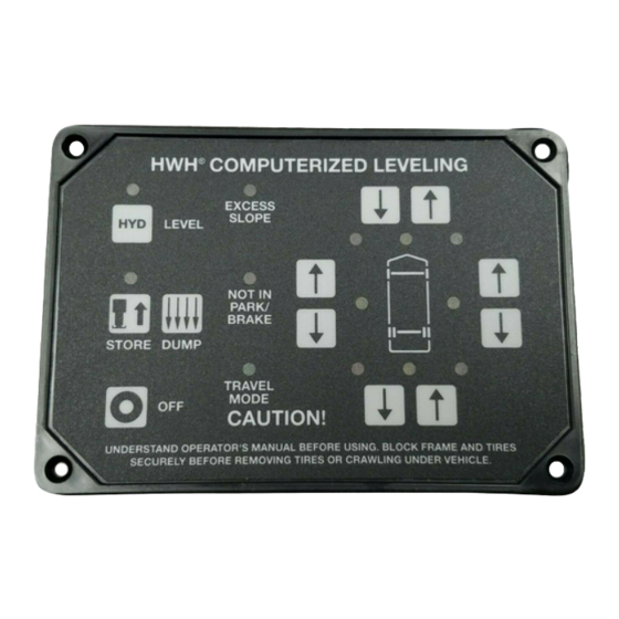
625 TOUCH PANEL
HWH COMPUTERIZED LEVELING
R
EXCESS
SLOPE
LEVEL
HYD
LUBE
NOT IN
PARK/
BRAKE
STEP
STORE DUMP
TRAVEL
MODE
OFF
CAUTION!
UNDERSTAND OPERATOR'S MANUAL BEFORE USING. BLOCK FRAME AND TIRES
SECURELY BEFORE REMOVING TIRES OR CRAWLING UNDER VEHICLE.
Ph: 800/321-3494 (or) 563/724-3396 | Fax: 563/724-3408
H H
W
CORPORATION
AND
LEVELING SYSTEM
HWH CORPORATION
(On I-80, Exit 267 South)
2096 Moscow Road | Moscow, Iowa 52760
www.hwh.com
R
625S SINGLE STEP TOUCH PANEL
HWH COMPUTERIZED LEVELING
R
EXCESS
SLOPE
AUTO
LEVEL
NOT IN
PARK/
BRAKE
AUTO
STORE
TRAVEL
MODE
CANCEL
CAUTION!
UNDERSTAND OPERATOR'S MANUAL BEFORE USING. BLOCK FRAME AND TIRES
SECURELY BEFORE REMOVING TIRES OR CRAWLING UNDER VEHICLE.
ML44818/MP04.2527
17JUN09
Advertisement
Table of Contents

Related Manuals for HWH Corporation 625


Summary of Contents for HWH Corporation 625
- Page 1 CORPORATION COMPONENT SELECTION INSTALLATION MANUAL HWH COMPUTER-C0NTROLLED LEVELING SYSTEM 625 OR 625 SINGLE STEP FOR MOTORIZED VEHICLES 625 TOUCH PANEL 625S SINGLE STEP TOUCH PANEL HWH COMPUTERIZED LEVELING HWH COMPUTERIZED LEVELING EXCESS EXCESS SLOPE SLOPE LEVEL LUBE AUTO LEVEL NOT IN...
- Page 2 SUSPENSIONS, TIRES AND COACH WEIGHTS MAKE IT IMPOSSIBLE TO ANTICIPATE AND ADDRESS ALL SELECTION OR INSTALLATION PROBLEMS AND POSSIBILITIES. SOME VEHICLE BUILDERS OR CHASSIS BUILDERS MAY USE PRACTICES DIFFERENT FROM THOSE IN THIS MANUAL. CONSULT HWH CORPORATION OR THE VEHICLE BUILDER FOR INFORMATION CONCERNING CORRECT SYSTEM CAPACITY AND TYPE FOR THE VEHICLE, INSTALLATION QUESTIONS, AND INSTALLATION OF OTHER HWH EQUIPMENT.
- Page 3 Jack Mounting Bracket Catalog, the Matchmaker Component Selection Program or the Standard Leveling System link is not suitable for your application, Contact HWH Corporation for assistance in selecting an appropriate pivot bracket/jack arrangement. The following information is needed to assist us in this selection process.
- Page 4 SECTION I 625/625S SERIES LEVELING SYSTEMS COMPONENT SELECTION The following chart shows the available capacities for kick-down and straight-acting jacks: Weight capacity 3,000# 4,000# 6,000# 9,000# 12,000# 16,000# 24,000# Kick-down style Straight-acting style To select the proper components for your application, especially when selecting mounting brackets and/or jacks, the vehicle must be available for inspection.
- Page 5 HWH may not fit every application, even when a specific application is listed. It is the installers responsibility to address mounting requirements and issues before starting the installation. When variations are encountered that require custom brackets or components, or typical mounting locations are not MP24.9722 available, contact HWH Corporation for assistance. 09JUL09...
- Page 6 SECTION I CLEARANCE AND MOUNTING DIMENSION CHART KICK - DOWN JACKS SIDE VIEW TOP VIEW GROUND LINE DIMENSION "I" INCLUDES SPRINGS. RETRACTED JACK EXTENDED STROKE MOUNTING MOUNTING BOLT DIMENSIONS DIMENSIONS WIDTH PATTERN 6000# SHORT 12.5" 19.5" 4.5" 12.0" 14.0" 19.0" 2.0"...
- Page 7 SIDE VIEW IMPORTANT: Dimensions listed here are for typical generic style jacks installed in the after market. For vehicle specific jacks, contact HWH Corporation for mounting and clearance dimensions or drawings of specific jacks. If needed, jacks with different mounting dimensions and spring arrangements may be available.
- Page 8 9.) Does the vehicle have a good set of batteries that are fully charged? IMPORTANT: Jacks used with 625 or 625S series leveling systems need a pressure switch on each jack. Generic jack kits may not come equipped with pressure switches. Make sure the appropriate jack pressure switches have been ordered and are present for the installation.
- Page 9 SECTION II 625/625S SERIES LEVELING SYSTEMS COMPONENT INSTALLATION Vehicles with spring suspensions. The ground clearances listed in the Dimension Charts apply to vehicles with a full load of fuel, water and equipment. If the vehicle is empty, typically 1 inch should be added to the listed dimensions. Also, if the vehicle is new, the vehicle may settle down 3/4 of an inch or more in the first year or 10,000 miles.
- Page 10 Connect welding ground to part being welded. NEVER weld to suspension parts such as spring shackles. NEVER weld across the bottom flange of the frame rail. Brackets should be located near a cross member. For additional information on the vehicle, chassis, brackets, and mounting location, contact the vehicle’s builder, the chassis or suspension supplier, or HWH Corporation. WARNING: THERE MAY BE FUEL LINES OR WIRE INSIDE THE FRAME RAIL.
- Page 11 Mounting brackets and jacks should be bolted using hardware supplied by HWH Corporation. Make sure all bolts are properly tightened. A minimum of grade 5 bolt should be maintained if substituting for hardware supplied by HWH Corporation. Any flat and/or lock washers must be used when supplied in hardware kits.
- Page 12 SIDE OF THE FRAME RAIL FROM WELDING HEAT AND SPLATTER. The jacks or jack mounting plates should be bolted using hardware supplied by HWH Corporation. Make sure all bolts are properly tightened. A minimum of grade 5 bolt should be maintained if substituting for hardware supplied by HWH Corporation.
- Page 13 SECTION II 625/625S SERIES LEVELING SYSTEMS COMPONENT INSTALLATION The air bags can be deflated by disconnecting the air line that goes from the height control valve to the air bag. The best access to accomplish this is probably at the height control valve. The air dump solenoid valve tees in between the height control valve and the air bag.
- Page 14 SECTION II 625/625S SERIES LEVELING SYSTEMS COMPONENT INSTALLATION The clear control box cover must be removed to program the sensing unit. Program the sensing unit as follows: Direction: Glass cover pointed to the "North" - move JP2 only. Glass cover pointed to the "South" - move JP1 and JP2.
- Page 15 HWH procedures must be followed when swaging hose. Crimping of hose ends is not allowed. Contact HWH Corporation or refer to ML24976 under "Information Bulletins" on the HWH web site for hose swaging information.
- Page 16 HOSE ROUTING FOR KICK-DOWN JACKS JACK PRESSURE SWITCH INSTALLATION KICK DOWN JACKS: 6000# KICK DOWN JACK- A short hose is attached to the jack at the factory. The hose is clamped to the pivot bracket. It can be moved to the opposite side of the jack if necessary to avoid heat sources or other obstacles.
- Page 17 We do not suggest altering harness lengths. The touch panel harness must never be altered for any reason. If a different length touch panel harness is needed, contact HWH Corporation. If you choose to alter the length of other HWH harnesses, all connections should be soldered and then protected with a glue filled shrink tube.
- Page 18 SECTION II 625/625S SERIES LEVELING SYSTEMS COMPONENT INSTALLATION 8.) PARK BRAKE/JACK INHIBIT CIRCUIT IMPORTANT: The park brake circuit inhibits the system from extending the jacks while the vehicle is moving. It is important that the park brake circuit is installed as explained. It is also important that the correct function of the park brake circuit is checked before the installation is completed.
- Page 19 SECTION II 625/625S SERIES LEVELING SYSTEMS COMPONENT INSTALLATION 9.) MASTER WARNING LIGHT/BUZZER INSTALLATION A MASTER JACKS DOWN WARNING LIGHT SHOULD BE USED WITH ALL SYSTEMS. A BUZZER MUST BE USED WITH SYSTEMS USING STRAIGHT-ACTING JACKS. The master warning light and buzzer will warn the driver that one or more jacks are extended slightly (straight-acting jacks) or in the vertical position (kick-down jacks) with the ignition on.
- Page 20 WHEN THE PARK BRAKE IS RELEASED. 625 system park brake test. Turn the ignition switch to the "ACC" position. Make sure the park brake is set. Push the "I" / "HYD" button. The on light above the button should come on. The "NOT IN PARK / BRAKE" light should not be on. Push on the foot brake so the vehicle can’t roll, then release the park brake.
- Page 21 SECTION III 625/625S SERIES LEVELING SYSTEMS SYSTEM START-UP AND ADJUSTMENTS Straight-acting jacks; 625S single step leveling system. Make sure the ignition is in the "ACC" position and the park brake is set. Push and release the front UP ARROW at 5 second intervals until both front jacks reach the ground and lift the vehicle 1 or 2 inches.
- Page 22 SECTION III 625/625S SERIES LEVELING SYSTEMS SYSTEM START-UP AND ADJUSTMENTS 2. 9000# JACKS: If the jack stopped short of being vertical it can be adjusted by loosening the lower actuator nut and tightening the upper actuator nut. If the jack goes past vertical, loosen the upper actuator nut and tighten the lower actuator nut.
- Page 23 SECTION III 625/625S SERIES LEVELING SYSTEMS SYSTEM START-UP AND ADJUSTMENTS 7.) FINAL CHECK LIST JACK PRESSURE SWITCH 1.) With all jacks fully retracted, check the oil level. The oil FOR 610 SYSTEMS level should be within 1 inch of the top of the reservoir.
- Page 24 625/625S SERIES LEVELING SYSTEMS JUMPER PLACEMENT FOR ELECTRONIC SENSING UNIT IMPORTANT: 325 AND 625 ELECTRONIC SENSING UNITS USED IN AFTER MARKET INSTALLATIONS OR REPLACEMENT SITUATIONS ARE PROGRAMMABLE. DURING INSTALLATION OF A SYSTEM OR REPLACEMENT OF AN ELECTRONIC SENSING UNIT DO NOT ASSUME THAT THE SENSING UNIT JUMPERS ARE PRE-SET. THE MOUNTED ORIENTATION OF THE CONTROL BOX ASSEMBLY AND THE SUSPENSION TYPE MUST BE ESTABLISHED IN ORDER TO SET THE JUMPERS AS NEEDED TO PROGRAM THE SENSING UNIT TO THE COACH.
- Page 25 625/625S SERIES LEVELING SYSTEMS JUMPER PLACEMENT FOR ELECTRONIC SENSING UNIT IMPORTANT: 325 AND 625 ELECTRONIC SENSING UNITS USED IN AFTER MARKET INSTALLATIONS OR REPLACEMENT SITUATIONS ARE PROGRAMMABLE. DURING INSTALLATION OF A SYSTEM OR REPLACEMENT OF AN ELECTRONIC SENSING UNIT DO NOT ASSUME THAT THE SENSING UNIT JUMPERS ARE PRE-SET. THE MOUNTED ORIENTATION OF THE CONTROL BOX ASSEMBLY AND THE SUSPENSION TYPE MUST BE ESTABLISHED IN ORDER TO SET THE JUMPERS AS NEEDED TO PROGRAM THE SENSING UNIT TO THE COACH.
- Page 26 SECTION IV 625/625S SERIES LEVELING SYSTEMS LEVEL SENSING UNIT ADJUSTMENT AND ACCURACY TOLERANCE SENSING UNIT ACCURACY TOLERANCE The sensing unit has an accuracy tolerance of ± 5.4 inches front to rear and ± 1 inch side to side on a 36 foot vehicle. Typical leveling results will be better.
- Page 27 SECTION IV - HYDRAULIC LINE CONNECTION DIAGRAM 625 SERIES LEVELING SYSTEM (WITH 4 STRAIGHT-ACTING JACKS) NOTE: BEFORE OPERATING ANY MANUAL VALVE RELEASE READ AND UNDERSTAND PROCEDURE FOR MANUAL JACK RETRACTION IN OPERATOR’S INSTRUCTIONS. THIS MANIFOLD IS SHOWN WITH (1) LARGE VALVE WITH A VALVE RELEASE "T"-HANDLE, (2) SMALL VALVES WITH VALVE RELEASE NUTS...
- Page 28 SECTION IV - HYDRAULIC LINE CONNECTION DIAGRAM 625 SERIES LEVELING SYSTEM (WITH 4 KICK-DOWN JACKS) NOTE: BEFORE OPERATING VALVE RELEASE NUTS, READ AND UNDERSTAND PROCEDURE FOR MANUAL JACK RETRACTION IN OPERATOR’S INSTRUCTIONS. LEFT FRONT RIGHT FRONT VALVE BREATHER RELEASE NUTS...
- Page 29 SECTION IV - HYDRAULIC SCHEMATIC DIAGRAM 625 SERIES LEVELING SYSTEM BI-AXIS LEVELING WITH STRAIGHT-ACTING JACKS NOTE: 50 PSI PRESSURE SWITCH RELIEF VALVE MAY NOT BE USED ON ALL 625 MANIFOLDS. 3500 P.S.I. HYDRAULIC ROOM EXTENSION POWER UNIT MANIFOLD LOCATED HERE...
- Page 30 SECTION IV - HYDRAULIC SCHEMATIC DIAGRAM 625 SERIES LEVELING SYSTEM BI-AXIS LEVELING WITH KICK-DOWN JACKS *50 PSI SWITCH MAY NOT BE RELIEF VALVE USED ON ALL 625 MANIFOLDS HYDRAULIC SOLENOID MANIFOLD POWER UNIT ASSEMBLY RETURN PRESSURE 3000 PSI SWITCH *50 PSI...
- Page 31 SECTION IV AIR LINE CONNECTION DIAGRAM SUSPENSION AIR BAGS AIR DUMP SOLENOID VALVES FROM WIRE HARNESS ARE ACTIVATED (OPENED) BY SEE ELECTRICAL A +12 SIGNAL. DIAGRAM FOR CONNECTION 4 AIR DUMP SOLENOID VALVES AND 4 HEIGHT CONTROL VALVES ARE SHOWN. THE AIR DUMP VALVE IS TO TEE INTO THE LINE BETWEEN THE AIR BAG AND THE HEIGHT CONTROL VALVE.
-
Page 32: System Diagram
SECTION IV - ELECTRICAL CONNECTION DIAGRAM 625 OR 625S SERIES LEVELING SYSTEM SYSTEM DIAGRAM PRESSURE PRESSURE SWITCH SWITCH WARNING WARNING SWITCH SWITCH 6235 2000 1000 6235 1200 2200 CONNECT TO TOUCH PANEL 12V IGNITION HWH COMPUTERIZED LEVELING MASTER EXCESS FUSE... - Page 33 SECTION IV - ELECTRICAL CONNECTION DIAGRAM 625 OR 625S SERIES LEVELING SYSTEM CONTROL BOX CONNECTION INFORMATION 12 PIN BROWN PIN 12 PIN 1 PIN 1 12 PIN PIN 1 PIN 12 BLACK 12 PIN PIN 1 8 PIN GRAY PIN 4...
- Page 34 SECTION IV - ELECTRICAL CONNECTION DIAGRAM 625 OR 625S SERIES LEVELING SYSTEM CONTROL BOX - LED - FUSE LOCATION AND DESCRIPTION RELAY DESCRIPTION FUSE 1-YELLOW RIGHT REAR COIL 2-RED RIGHT REAR OUTPUT F1 - 15 AMP 3-YELLOW LEFT REAR COIL...
- Page 35 SECTION IV ELECTRICAL CONNECTION DIAGRAM CIRCUIT BOARD CONNECTOR AND PIN LOCATIONS CR10 CR11 IGN OUT CL CH LD21 (SHIELD) LD22 LD23 4 PIN GRAY LD24 CONNECTOR LD25 LD26 LD27 LD28 A32433 PROGRAM CHIP LD39 LD36 LD37 LD38 MP84.2402 17JUN09 MP85.185J...
- Page 36 SECTION IV - ELECTRICAL CONNECTION DIAGRAM 625 OR 625S SERIES LEVELING SYSTEM LEVELING MANIFOLD - PUMP AND MASTER RELAYS TO 50 LB PRESSURE SWITCH - 8101 LEVELING MANIFOLD 3400 7601 2400 7600 1400 6240 4400 6240 TO HWH GROUND STUD - 6240...
- Page 37 SECTION IV - ELECTRICAL CONNECTION DIAGRAM 625 OR 625S SERIES LEVELING SYSTEM LEVELING MANIFOLD - AIR DUMP - PUMP AND MASTER RELAYS TO 50 LB PRESSURE SWITCH - 8101 LEVELING MANIFOLD 3400 7601 AIR DUMP SOLENOID 2400 AIR DUMP SOLENOID...
- Page 38 SECTION IV - ELECTRICAL CONNECTION DIAGRAM 625 OR 625S SERIES LEVELING SYSTEM TOUCH PANEL CONNECTIONS HWH COMPUTERIZED LEVELING EXCESS SLOPE EXTEND EXTEND AUTO LEVEL NOT IN MANUAL PARK/ BRAKE AUTO MANUAL STORE DUMP RETRACT RETRACT TRAVEL MODE EMERGENCY STOP CAUTION! UNDERSTAND OPERATOR’S MANUAL BEFORE USING.
- Page 39 SECTION IV - ELECTRICAL CONNECTION DIAGRAM 625 OR 625S SERIES LEVELING SYSTEM MASTER LIGHT/BUZZER CONNECTIONS A MASTER WARNING INDICATOR SHOULD ALWAYS BE USED. WHEN THE LEVELING SYSTEM HAS STRAIGHT ACTING JACKS A WARNING BUZZER MUST BE USED. WHEN ONLY A RED MASTER WARNING LIGHT IS USED THE (+) VOLTAGE FOR THE LIGHT COMES FROM THE CONTROL BOX.
Need help?
Do you have a question about the 625 and is the answer not in the manual?
Questions and answers