Table of Contents
Advertisement
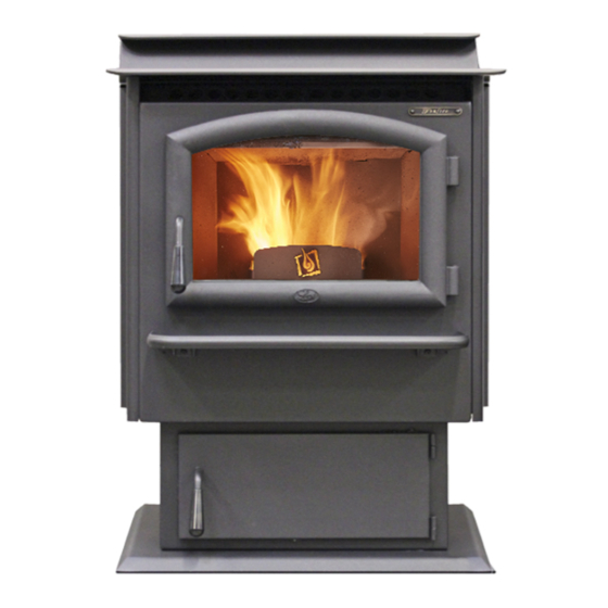
Foxfire
Pellet Stove
-- Please read this entire manual before
installation and use of this pellet fuel-
burning room heater. Failure to follow
these instructions could result in
property damage, bodily injury, or even
death.
-- Contact local building or fire officials
about restrictions and installation
inspection requirements in your area.
-- Save these instructions.
Installer: After installation give this manual to the home-
owner and explain operation of this heater.
Consumer: Retain this manual for future reference.
$10.00
Part # 100-01402
Copyright 2017, T.I.
4170126
Horizontal or Vertical Vent
•
•
Freestanding Stove
•
Mobile Home Approved
•
Class A Chimney Retrofit
•
Hearth Stove into Existing
Masonry Chimney , Masonry
Fireplace, or Z.C. Fireplace
Tested and Listed by:
ASTM E1509-12 ULC-S627
www.travisproducts.com
12521 Harbour Reach Drive SW
Mukilteo, WA 98275
Advertisement
Table of Contents

Related Manuals for Lopi Foxfire


Summary of Contents for Lopi Foxfire
- Page 1 Foxfire Pellet Stove Horizontal or Vertical Vent • • Freestanding Stove • Mobile Home Approved • Class A Chimney Retrofit • Hearth Stove into Existing Masonry Chimney , Masonry Fireplace, or Z.C. Fireplace -- Please read this entire manual before...
-
Page 2: Important Information
Introduction Introduction We welcome you as a new owner of a Foxfire pellet stove. In purchasing an pellet stove you have joined the growing ranks of concerned individuals whose selection of an energy system reflects both a concern for the environment and aesthetics. The Foxfire pellet stove is one of the finest home heaters the world over. -
Page 3: Table Of Contents
Table of Contents Heating Specifications ..........7 To Adjust the Heat Output ........26 To Shut Down ............26 Dimensions ............... 7 Thermostat Programs ......... 27 Electrical Specifications .......... 7 How to Get to the Thermostat Program Screen ..27 ... - Page 4 Safety Precautions HOT WHILE IN OPERATION. Contact your local building officials KEEP CHILDREN, CLOTHING, to obtain a permit and information AND FURNITURE AWAY. on any installation restrictions or CONTACT MAY CAUSE SKIN inspection requirements in your BURNS. area. Notify your insurance company of this appliance as well.
- Page 5 Safety Precautions Allow the appliance to cool Maintain the door and glass seal completely before carrying out any and keep them in good condition. maintenance or cleaning. Do not operate this heater with broken or missing glass. Do not slam the door or strike the glass.
- Page 6 Safety Precautions Do not throw this manual away. Disconnect the power before This manual has important performing any maintenance. This operating and maintenance Manual instructions that you will need at a later time. Always follow the instructions in this manual. Travis Industries, Inc.
-
Page 7: Heating Specifications
Installation (For Qualified Installers Only) Heating Specifications Approximate Maximum Heating Capacity (in square feet)* ..........Up to 2,500 Sq. Feet BTUs Per Hour ....................... 13,940 to 49,200 ** Burn Rate (Pounds per Hour)*** ..................1.7 to 6 Maximum Burn Time on Low Burn*** ................47 Hours Hopper Capacity ...................... -
Page 8: Before You Begin
Installation (For Qualified Installers Only) Before You Begin READ THIS ENTIRE MANUAL BEFORE YOU INSTALL AND USE THIS HEATER. FAILURE TO FOLLOW THE INSTRUCTIONS MAY RESULT IN PROPERTY DAMAGE, BODILY INJURY, OR EVEN DEATH. Check with local building officials for any permits required for installation of this pellet heater and notify your insurance company before proceeding with installation. -
Page 9: Planning The Installation
Installation (For Qualified Installers Only) Planning the Installation HINT: Have an authorized Travis Industries dealer install this heater. If you install the heater yourself, have your dealer review your installation plans. HINT: Sketch out a detailed plan of the installation including dimensions. Then verify the dimensions with the requirements listed in this manual. -
Page 10: Clearances
Installation (For Qualified Installers Only) Clearances Straight Installations Through the Wall Installations Interior Vertical Vents Vent Clearance* 2" Minimum** 3" Minimum "Tee" 6" Minimum 6" Minimum Floor Protection 6” Minimum 6” Minimum 6" Minimum 6" Minimum Corner Installations Through the Wall Vents Interior Vertical Vents 3"... -
Page 11: Venting The Pellet Stove
Installation (For Qualified Installers Only) Venting the Pellet Stove INSTALL VENT AT CLEARANCES SPECIFIED BY THE VENT MANUFACTURER. DO NOT CONNECT THE PELLET VENT TO A VENT SERVING ANY OTHER APPLIANCE OR STOVE. DO NOT INSTALL A FLUE DAMPER IN THE EXHAUST VENTING SYSTEM OF THIS UNIT. ... -
Page 12: Pellet Vent Type
Installation (For Qualified Installers Only) Pellet Vent Type Must be 3" (76mm) or 4” (102mm) diameter Type "L" (except for masonry fireplace installations) - or - connect the vent to a factory built type "A" chimney. Installing the Pellet Vent Seal each vent section (including the connection to the heater, adapters, elbows, etc...) following the directions provided by the vent manufacturer or by injecting a liberal amount of 500 deg. -
Page 13: Mobile Home Requirements
Installation (For Qualified Installers Only) Mobile Home Requirements Outside air is required (used for combustion) - see the directions below. The heater must be bolted to the floor (Some states do not require this; check with your local building department). -
Page 14: Alcove Installation Requirements
Installation (For Qualified Installers Only) Alcove Installation Requirements When the pellet stove is placed in a location where the ceiling height is less than 7' (2.134 M) tall, it is considered an alcove installation. Because of the reduced height, the requirements listed below must be met. -
Page 15: External Thermostat Installation
Installation (For Qualified Installers Only) External Thermostat Installation This heater may be used with an external thermostat or remote. WARNING: Use only a dry-contact thermostat or remote (also called millivolt thermostat/remote). Use of a voltage producing thermostat (24v, 120v AC, etc.) will damage the appliance. ... -
Page 16: Installation Examples
Installation (For Qualified Installers Only) Installation Examples Installation Example: Direct "Through-the-wall" Installation Horizontal Rain Cap Type "L" Vent 12" Minimum House Shield (used to protect exterior wall from soot discoloration) is HIGHLY RECOMMENDED Wall Thimble 3" Minimum (note clearance between vent and combustibles) 6"... -
Page 17: Interior Vertical Installation
Installation (For Qualified Installers Only) Installation Example: Interior Vertical Installation Vent Clearance* 2" Minimum** "Tee" 6" Minimum Floor Protection 6” Minimum Vertical Cap 6" Minimum 24" Minimum Storm Collar Roof Flashing Insulation must maintain clearance. Vent must Ceiling Support / Fire Stop Spacer maintain clearance to combustibles. -
Page 18: Class A Chimney Retrofit
Installation (For Qualified Installers Only) Class A Chimney Retrofit Non-Combustible Block-Off Class A Chimney Storm Collar Roof Flashing Class A Chimney must maintain clearances outlined in the chimney’s installation instructions (usually 2"). Class A Chimney Ceiling Support Use "L" Vent to Class A Chimney Adapter - or - Run vent through chimney and use non- comustible block-off at top of flue. -
Page 19: Masonry Fireplace Hearth Stove
Installation (For Qualified Installers Only) Installation Example: Masonry Fireplace Hearth Stove Vertical Cap "L" Vent Cover Plate (non-combustible) Storm Collar Seal the cover plate with silicone. "L" Vent Flex Section Allow room for the hopper lid to open Lintel Outside air may be 6"... -
Page 20: Zero-Clearance (Metal) Fireplace Hearth Stove
Installation (For Qualified Installers Only) Installation Example: Zero-Clearance (Metal) Fireplace Hearth Stove Non-Combustible Block-Off Seal the block-off with silicone and/or insulation. Do not obstruct or seal the outer chamber of the air-cooled chimney "L" Vent "L" Vent Flex Section Allow room for the hopper lid to open 6"... -
Page 21: Freestanding Masonry Chimney
Installation (For Qualified Installers Only) Installation Example: Freestanding Masonry Chimney Vertical Cap "L" Vent Cover Plate (non-combustible) Storm Collar Seal the cover plate with silicone. "L" Vent Flex Section "L" Vent Sections Vent Clearance* Clean-Out Access 6" Min. Install vent at clearance specified by the vent manufacturer. ©... -
Page 22: Safety Notice
Operation Safety Notice READ THIS ENTIRE MANUAL (ESPECIALLY THE "SAFETY PRECAUTIONS" ON PAGES 4 AND 5) BEFORE USING THIS HEATER. FAILURE TO FOLLOW THE INSTRUCTIONS MAY RESULT IN PROPERTY DAMAGE, BODILY INJURY, OR EVEN DEATH. DO NOT UNPLUG THE HEATER TO TURN IT OFF. THIS HEATER RELIES UPON ELECTRICITY TO PUSH THE FLUE GASES OUT THE PELLET VENT –... -
Page 23: Loading Pellets
Operation Loading Pellets Lift the hopper lid to its vertical position. Pour pellets into the hopper. NOTE: If the hopper lid is opened for more than 1 minute, the heater will enter shut down cycle. If this happens, simply restart the heater. WARNING: The heater top becomes hot during operation. -
Page 24: Modes Of Operation - Manual Or Thermostat
Operation Modes of Operation – Manual or Thermostat This heater has two modes: Manual or Thermostat. To switch between modes, press the Thermostat Button. Fan Setting T-Stat Mode T-Stat Mode Manual Mode Heat Setting Manual Mode Thermostat Mode Manual Mode requires the user to turn the Thermostat (T-Stat) Mode allows you to use a heater on and off manually and select the heat thermostat to control room temperature. -
Page 25: Manual Mode
Operation Manual Mode Manual mode requires the user to turn the heater on and off manually and select the heat output setting. To Start To Shut Down Press the On/Off Button to start and stop the Press the On/Off button on the control panel. The heater. -
Page 26: Thermostat (T-Stat) Mode
Operation Thermostat (T-stat) Mode Thermostat (T-stat) Mode allows you to use the internal (or external) thermostat to control room temperature. The heater automatically turns on when the temperature drops below the thermostat setting and turns off (or to low) once the thermostat setting is met. A wireless thermostat is available from Travis Industries (see your dealer for details). -
Page 27: Thermostat Programs
Operation Thermostat Programs This heater comes with three thermostat programs built in. Each program is unique and allows you to modify your thermostat setting to your preference. How to Get to the Thermostat Program Screen Press the Menu Button Until “T-stat Program” appears on the digital readout. Use the Heat Setting slider on the touch screen to adjust between the three thermostat programs. -
Page 28: Fan Setting
Operation Fan Setting There are two options for adjusting the room-air circulating fan. The fan will turn on only after the heater is up to temperature (approximately 15 minutes after starting). Manual Adjustments Use the Fan Setting slider to set the fan speed. Fan Setting The fan remains on, even at its lowest setting. -
Page 29: Heater Status
Operation Heater Status This heater has unique phases of operation (also called Heater Status). The descriptions below details these phases to help the homeowner better understand how the pellet heater works. Standby The heater is plugged in, cool, and is not in operation. Start-Up Once the heater is started, it will go through Start-Up phase. -
Page 30: Menu Button
Operation Menu Button Fan Setting The menu button allows access to the internal settings on the heater. To access, press the menu button (the screen below will be shown). Press the menu button Press for next setting. again to scroll through the options listed Change setting with slider. -
Page 31: Power Outages
Operation Power Outages Because this stove relies upon a blower to evacuate smoke, some smoke may enter the home during a power outage. Leave the door closed to keep the possibility of smoke spillage to a minimum. NOTE: Travis Industries recommends a minimum vertical vent of 5’ to ensure adequate draft during a power outage. -
Page 32: Stove Maintenance
Maintenance Stove Maintenance The following section details extensive maintenance procedures. We strongly suggest these items be carried out by a trained service technician, possibly by a service agreement set up with your dealer. NOTE: Pellet quality may vary by supplier. Your maintenance schedule may need to be revised to accommodate the pellets used. -
Page 33: Stove Maintenance Tools
Maintenance Stove Maintenance Tools Included with the stove are three tools for maintenance: a bottle brush, brush and the cleaning tool. Stove Tool Storage The stove tools may be stored on the hooks on the back of the stove. To use the hooks for the first time, bend the hooks with a screwdriver or needle-nose pliers, then hang the tools on the hooks as shown below. -
Page 34: Weekly Maintenance - Inspect The Burn
Maintenance Weekly Maintenance (or Every 5 Bags of Pellets) - Inspect the Burn Once a week you should inspect the flame quality inside your appliance. When burning on high, the flames should be bright orange. If the flames seem to be coming only from the sides, or are orange/black, turn the heater off and check for clinkers (ashes that solidify into a clump). - Page 35 Maintenance 3. Use the cleaning tool to scrape away hardened clinkers or buildup on the burn platform. Use the narrow tip to clear any plugged holes. The burn platform must be free from buildup for the pellets to burn completely. 4.
- Page 36 Maintenance Remove the burn platform from the platform holder. Clean the inside of the platform holder. © Travis Industries 4141007 100-01402...
-
Page 37: Cleaning Behind The Firebox Liners
Maintenance Cleaning Behind the Firebox Liners Front View of Firebox Liners Isometric View (note how the top liner has a flange that bends down) The firebox liners help trap flyash before it enters the exhaust blower. Remove the liners and clean the area behind them following the directions below. -
Page 38: Monthly Maintenance - Clean The Glass
Maintenance 5. Remove the rear liner. Lift it up and remove it from the firebox. 6. With the liners removed, clean all flyash and debris from the firebox. Clean the liners before replacing. Make sure to clean the heat exchanger on the firebox ceiling. Monthly Maintenance (or Every 20 Bags of Pellets) - Clean the Glass Open the doors and clean the glass with a non-abrasive... -
Page 39: Monthly Maintenance - Empty The Ashpan
Maintenance Monthly Maintenance (or Every 20 Bags of Pellets) – Empty the Ashpan MAKE SURE THE HEATER HAS FULLY COOLED (APPROXIMATELY 45 MINUTES) BEFORE CONDUCTING SERVICE. THE ASHPAN MUST BE IN PLACE WHILE THE HEATER IS IN USE. The ashpan will accumulate ash as you use the appliance. See the steps below to empty the ashpan. 1. - Page 40 Maintenance Yearly Maintenance (or Every Ton of Pellets) - Clean the Lower Exhaust Duct 1. Remove the exhaust duct cover as shown below. It lifts up and pivots out. These hooks hold the duct cover in place. 2. Remove the exhaust channel cover plate and gasket (a single wingnut holds it in place). When replaced, make sure the gasket on the cover plate seals the cover plate against the exhaust channel.
- Page 41 Maintenance 3. Clean the exhaust channel with the bottle brush or vacuum. 4. Clean the combustion blower with the bottle brush or vacuum. NOTE: Take care to prevent damaging the combustion blower impellers. © Travis Industries 4141007 100-01402...
- Page 42 Maintenance Yearly Maintenance (or Every Ton of Pellets) - Clean the Convection Blowers 1. The side panels must be removed to access the convection blowers. Starting with the left side panel, unscrew the air control rod from the left side and place it aside. 2.
- Page 43 Maintenance 5. The two convection blowers may be removed and cleaned. Remove the three screws holding the blower assembly in place (see photo below). 5/16" Nutdriver Disconnect the blower assembly (the wiring may remain in place during cleaning. Clean all dust and debris from the convection blower.
-
Page 44: Yearly Maintenance - Clean Lower Exhaust Duct40 Yearly Maintenance - Clean Convection Blowers42 Yearly Maintenance - Clean Negative
Maintenance Yearly Maintenance (or Every Ton of Pellets) - Clean the Negative Pressure Tube 1. The negative pressure tube is located behind the right side convection blower. Disconnect the end of the tube from the barbed nipple. Make sure the tube is clean. 2. -
Page 45: Yearly Maintenance - Adjust Door Cam
Maintenance Yearly Maintenance (or Every Ton of Pellets) - Adjust Door Cam The door cam should be tight enough to pull the door against the face of the stove yet not so tight as to not allow full handle rotation. To tighten the door cam, remove the door handle and remove one of the washers between the door frame and cam (the washer may be stored for future use by placing it between the cam and nut). -
Page 46: Troubleshooting Table
Maintenance Troubleshooting Table Contact Travis Industries for details. Replacement Parts Contract your Travis Industries Dealer for replacement parts. Use only replacement parts from Travis Industries designed specifically for this heater. Door Parts ID # Description Part # ID # Description Part # Glass Gasket (3/8”... -
Page 47: Wiring Diagram
Maintenance Wiring Diagram FOXFIRE / DEERFIELD WIRING POWER BRANCH Line White Neutral Ground PIN 1 Gray Green Chassis PIN 5 White Fuse - 5 Amp PIN 3 Gray PIN 2 Orange Comb. Blower PIN 7 Yellow Igniter PIN 4 Blue Conv. - Page 48 Safety Label WARNING - DO NOT REMOVE OR COVER THIS LABEL SERIAL NO: MODEL: FOXFIRE / DEERFIELD Listed Pelletized Solid Fuel Burning Appliance Report No. 101457967PRT-001 Also for use in mobile homes Control No. 4000515 Certified for US and Canada Conforms to ASTM E1509-12, Room Heater Pellet Burning Type (UM) 84 HUD;...
- Page 49 Limited 7 Year Warranty To register your TRAVIS INDUSTRIES, INC. 7 Year Warranty, complete the enclosed warranty card and mail it within ten (10) days of the appliance purchase date to: TRAVIS INDUSTRIES, INC., 12521 Harbour Reach Drive, Mukilteo, WA 98275. TRAVIS INDUSTRIES, INC. warrants this appliance (appliance is defined as the equipment manufactured by Travis Industries, Inc.) to be defect-free in material and workmanship to the original purchaser from the date of purchase as follows: Check with your dealer in advance for any costs to you when arranging a warranty call.
- Page 50 Limited 7 Year Warranty IF WARRANTY SERVICE IS NEEDED: If you discover a problem that you believe is covered by this warranty, you MUST REPORT it to your Travis dealer WITHIN 30 DAYS, giving them proof of purchase, the purchase date, and the model name and serial number. Travis Industries has the option of either repairing or replacing the defective component.
- Page 51 Limited 7 Year Warranty © Travis Industries 4141007 100-01402...
- Page 52 Index Alcove Installation Requirements ..... 14 Installation Example: Zero-Clearance (Metal) Fireplace Hearth Stove ........ 20 Before You Begin ..........8 Installation Options ..........8 Check for Air Leaks .......... 45 Installing the Pellet Vent ........12 Checking the Ashpan ........39 Introduction ............
Need help?
Do you have a question about the Foxfire and is the answer not in the manual?
Questions and answers