Advertisement
Quick Links
Advertisement

Related Manuals for Fixturlaser SMC

Summary of Contents for Fixturlaser SMC
- Page 1 USER MANUAL Fixturlaser SMC...
-
Page 3: Table Of Contents
CONTENT General presentation General settings Supervisor module Balancing module Maintenance Technical specification USER MANUAL FIXTURLASER SMC, edition 1.3 (November 2017) -
Page 5: General Presentation
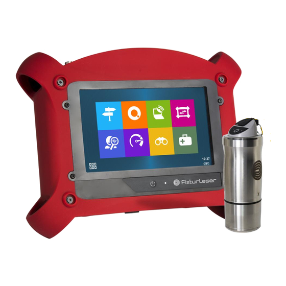
FIXTURLASER SMC is available in 2 versions. The FIXTURLASER SMC standard (red rubber) is for safe area, and the FIXTURLASER SMC-EX (black rubber) for ATEX Zone II area. Always refer to the product marking to know which version you are using. All functionalities described in this manual are applicable to both versions. - Page 6 List of symbols and warning on the instrument Warning: Whenever this symbol is present on the device, refer to the safety instructions and user manuals. The table below lists the warning signs and security present on the instrument. Symbol Signification Position Laser radiation Rear side (bottom)
- Page 7 Laser maintenance: The laser does not need maintenance or adjustment excluding cleaning the glass with a cotton swab. Always shut off completely the device FIXTURLASER SMC before this operation. Caution: Use of controls or adjustments or performance of procedures other than those specified herein may result in hazardous radiation exposure.
- Page 8 1.3 FIRST POWER UP The instrument turns on automatically a few seconds after being connected to the mains through the power supply module. If the battery level is too low, the charge starts and goes on as long as the instrument is connected to its power supply.
- Page 9 1.4 USER INTERFACE FIXTURLASER SMC starts on its “Home screen”. It is a touch screen and a simple pressure on it gives access to the application modules installed on the instrument and to 2 side panels: Access to application modules...
- Page 10 1.5 CONNECTIONS Connectors A to D on the top of the instrument Antenna for WLS sensor and Wi-Fi Those connectors can be used in industrial environment. They are IP65 Connector A Channels 1. Use this connector when the instrument is set in single-channel mode. •...
- Page 11 Connector C Tachometer input, Stroboscope output, Power supply input. It it is marked in yellow as well as all cables used on this connector • Contact A: Common • Contact B: Instrument power input • Contact C: 5 Vdc output •...
- Page 12 Connectors E to I behind the trapdoor Those connectors are behind a trapdoor. It must remain close in industrial environment to preserve the IP65 protection. Use those connectors only in office environment. Connector E: Power supply input Connector F: Ethernet RJ45 Connector G: USB 2 type A host (for USB memory stick) Connector H:...
- Page 13 1.6 BUILT-IN SENSORS The back of the instrument gives access to the built-in sensors. High-power LED for Pyrometer window stroboscope and camera flash Camera window Laser beam source for pyrometer sighting For the stroboscope and the pyrometer, please see the safety instructions delivered with the instrument (printed and on the USB STICK)
- Page 14 1.7 WIRELESS SENSOR FIXTURLASER SMC can be used with a wireless triaxial accelerometer (WLS Sensor). This chapter described how to use FIXTURLASER SMC with this sensor. WLS sensor battery Use the USB cable and charger supplied with the sensor. The connector is protected by the rubber cap on the top of the sensor.
- Page 15 ——— instrument - - - - - WLS has detected the instrument. The connection is only effective when you have in FIXTURLASER SMC status summary Switch off - - - - - Stop in progress (press 7 s on/off) WLS is switched off...
- Page 16 PC (10 ≠ 12) ▪ Mask = 255.255.255.0 Once the setting is done, to access the data use FIXTURLASER SMC IP address, e.g., in the Explorer type “\\192.168.1.10\Data”. • PC- FIXTURLASER SMC connection through LAN Network: o On PC: Setup Network ▪...
- Page 17 If there is a DNS, it is also possible to access the instrument with its name. The name is FIXTURLASER SMC_serial_number (e.g., FIXTURLASER SMC_10015). Once the setting is done, to access the data use FIXTURLASER SMC IP address, e.g., in the Explorer type “\\FIXTURLASER SMC_10015\Data”.
- Page 18 • Wi-Fi LAN connection PC- FIXTURLASER SMC setting without WLS sensor: Note: WLS sensor cannot be used simultaneously with this mode. o On FIXTURLASER SMC: Setting > Network > Wi-Fi part ▪ Enabled: Yes ▪ Adhoc: No ▪ Save the setting Setting >...
- Page 19 1.9 STATUS INDICATIONS Status summary The status is indicated at the bottom of the right-hand side of the screen • General status o Date and time o Battery level of the instrument o If Wireless measurement mode is selected, WLS connection status: ▪...
- Page 20 1.10 SHORTCUTS PANEL From any screen, button opens the Shortcuts panel. It gives direct access to a group of functions. The list of accessible functions depends of the current screen. Photo • From the Supervisor module: o Measurement list screen: Take an inspection picture o Map mode at location level: Take a location picture o Map mode at machine level: Take a machine picture •...
- Page 21 Keyboard details: Validate and return to previous screen Cancel: return to previous screen Character with no selection bar modification Delete all characters Delete last Select character keyboard type • Keyboard type: o EN: English o FR: French o PT: Portuguese o CN: Chinese •...
- Page 22 Listening to the signal Before using a headphone, please read the safety instructions delivered with the instrument (printed and on the USB STICK) • From the Supervisor module, measurement list screen: listen to the signal of the sensor • From the Supervisor module, time wave display screen: listen to the recorded signal Make sure to set the volume to a low level before starting to listen Press to start and then adjust the level to your convenience.
- Page 23 2 times. Use to return to the initial frequency. Screenshot From anywhere, you can save a screen copy. Images are stored in folder “Screenshots”. Connect your PC to FIXTURLASER SMC to copy them (see § 1.8). Settings See CHAPTER 2. Home From anywhere you can go directly to the home screen.
- Page 24 It is recommended to disconnect the charger from the mains when you are not using it. Battery replacement • Safety instructions: o Do not use batteries other than type PIL1133 provided for FIXTURLASER SMC and identified as 01dB Metravib WILPA 2344A 1.20...
- Page 25 o Do not open or disassemble the battery pack. The pack includes protections and an assembly essential for the safety that should be changed in no case. o The battery pack is interchangeable only for maintenance purposes. The operating lifetime of the pack is sufficient for a full working day.
- Page 26 o When inserting the battery, make sure not to hurt the pack. The insertion must be done without forcing excessively. When in doubt, pull out the battery and check that nothing is blocking its insertion. o According to the battery model, check the orientation of the connector: ▪...
-
Page 27: General Settings
2 GENERAL SETTINGS Access: Shortcuts panel > Settings 2.1 MEASUREMENT • Acquisition power supply permanent or not: If this option is set to YES, the acquisition components are permanently supplied. If it is set to NO, its supply is activated only when a measurement is to be carried out, but it requires a short waiting time before signal stabilisation. - Page 28 Check if FIXTURLASER SMC is set to work with a WLS sensor: Shortcuts > Setting > > Accelerometer link = Wireless • Check if the serial number of the sensor is that declared in FIXTURLASER SMC Shortcuts > Setting > Wireless sensor •...
- Page 29 2.3 TACHOMETER First tab: Tachometer setup • Adjustment of tachometer parameters: o Input range: select the range according to the tachometer signal: +/-10V, 0/-24V, 0/+24V o Coupling: ▪ DC: default setting ▪ AC: a 0.3Hz high-pass filter is applied. This can be used if the DC component of the signal is changing during measurement (for example: signal from a proximity probe during run-up / coast-down).
- Page 30 2.4 SPECTRUM DISPLAY Set the amplitude type, unit of spectrum and rotation speed: • Spectrum amplitude: Linear, Exponential, dB • Frequency and rotation speed unit: Hz, CPM, Order Note: If ‘Order’ is selected, it is necessary to have machine rotation speed different from 0. In this case, spectrum frequency axis is expressed in Hz.
- Page 31 2.7 ABOUT Display of: • Product version: Main firmware, DSP, Hardware • Instrument serial number • Network addresses • License information Input of: • License number to upgrade the instrument Note: The License number is only accessible if this page is open from the home screen. •...
- Page 32 2.9 NETWORK Access by network (“Remote Display and Control” function) • Password: To protect remote access from a PC (see § 1.12) Remote access • Server address: Input the address of the RDP server. • Login: Username • Password: Corresponding password Ethernet configuration parameters: For more details, see §...
- Page 33 Put update firmware (.czip file) on a USB memory key. Note: The memory must have only one update file. • Connect the system to its power supply. • Plug the USB memory key in FIXTURLASER SMC connector G. • Shortcuts > Setting > Update firmware •...
-
Page 34: Auto Test
2.12 AUTO TEST Run tests on the main components of the instrument. This operation takes about 3 mn. Note: • This function is only accessible if this page is open from the home screen. • Unplug the power supply • Unplug all sensors (connector A, B, C and D) •... -
Page 35: Supervisor Module
FIXTURLASER SMC offers all functions to manage the diagnostic of a machine in the field: • Built in machine creation •... - Page 36 The modifications can be saved on the existing machine or duplicated into a new machine. 3.2 MAKE MEASUREMENTS Machine list screen This screen lists all the machines loaded in the instrument. On the top of the screen you can select how to sort the machines as follows: •...
- Page 37 Measurement screen This screen displays the points and the list of measurements to be done if the function Acquisition is used. The group of point displayed together depends on: • The instrument channel number • The setting of the point done on the PC •...
- Page 38 Header description Measurement Diagnosis Sensor pictogram point or location indicator or picture Machine ID Measurement Main direction for Input type date vertical machine...
- Page 39 Sensor pictogram or picture • Position pictogram: o For tri-axial measurement it is first necessary to select the pictogram indicating the position of sensor on the bearing. It is only necessary to do it during the first measurement as the selection is saved on the PC database when the data are downloaded.
- Page 40 ▪ For vertical shaft: Axial (A) , Radial main (//) Radial perpendicular (P or ) • Sensor position picture: It is possible to replace the pictogram by a picture of the sensor. This picture is useful if you intend to do several controls on the same machine over the time. It can help the user to position the sensor exactly at the same place at each control.
- Page 41 Acquisition screen The instrument takes in one shot all measurements with the same input type for all the points grouped together. The channel association rules are explained in § 1.5. Progress bar: During the acquisition, there is a succession of 2 progress bars: •...
- Page 42 3.3 DISPLAY VIBRATION MEASUREMENTS This function displays the result of the selected measurement. If acquisition is not yet performed, it displays directly the live values. There are 2 types of display: • Overall levels • Low frequency Spectrum (used for rotation speed adjustment) For the spectrum, a first click on a curve selects it as the current one, a 2nd click sets a cursor.
- Page 43 • Side band The central cursor and the first side band cursor are automatically adjusted on the true frequency of a maximun by interpolation. Side band frequencies in coincindence with a maximum are marked by a sign. Select active cursor, central frequency or side band. Indications: •...
- Page 44 Take a temperature reading on a bearing Temperature measurement using the pyrometer For the pyrometer please read the safety instructions delivered with the instrument (printed and on the USB STICK) To make a measurement of the bearing temperature, call the pyrometer from the shortcut panel •...
- Page 45 The accuracy of the rotation speed input into the system will significantly affect the reliability of the diagnostic result. With Fixturlaser SMC, it possible to measure the rotation speed using the built-in stroboscope. (For more details on the use of the strobe light, see § 1.10).
- Page 46 3.5 RUN AUTOMATIC DIAGNOSIS This function gives directly the machine diagnosis instantly after your measurement. The diagnosis information is: • A pictogram giving the general status of the machine: The machine is good The machine is still acceptable The machine is not acceptable •...
- Page 47 Inspection vocal note: See § 1.10. The vocal inspection note remains available in FIXTURLASER SMC for the end user as long as the measurement is not deleted, but also automatically sent to a remote expert if a request for assistance is made (see §...
- Page 48 On the PC: Wait for the FIXTURLASER SMC to be displayed as an external drive on the computer. It usually takes about 30s maximum. If it takes more time, it may be due to a previous bad disconnection. To solve the problem, you can: •...
-
Page 49: Balancing Module
FIXTURLASER SMC is a universal tool that can be adapted to the entire base of machines to be balanced on site, regardless of the size and complexity of the rotors, by managing up to 4 balancing planes: •... - Page 50 4.1 FOLDER LIST This creates a management folder used to sort balancing tests. A folder can be used to store, for example, tests on the same machine or all balancing done for a customer. Functions of the screen: Go to selected folder: see § 4.3. Create a new folder in the list.
- Page 51 Use the tachometer accessories delivered in your balancing kit. For the setting of the tachometer input see § 2.3. A pulse is sent to FIXTURLASER SMC for each rotation of the machine. Note: It is recommended to have a pulse width at least larger than 2% of the rotation period.
- Page 52 4.4 SETUP This screen includes 4 tabs. They are used to define the balancing and the type of measurement used to perform the balancing process. Values can be directly modified. If some modifications have been made, a confirmation message to save them or not is asked before going to another screen.
- Page 53 Machine setup This tab gives access to following parameters: • Number of planes: 1 to 4 This refers to the number of planes on which balancing weights are to be installed. This number also determines the number of measurement points, as well as the number of runs required to perform the balancing: o Number of points = number of planes o Number of runs = 1 (Free run) + number of planes (Trial runs)
- Page 54 Measurement setup This tab gives access to following parameters: • Number of channels: 1 or 2. This value is only accessible for a 2-plane balancing. If 1 is selected at each run, each point is measured one after the other one. In all other cases, the number of channels is equal to the number of planes.
- Page 55 Sensor position setup This tab gives access to following parameters: • For each point: o Point identification: Up to 10 characters o Channel number: For information o Angular position of the sensor: Optional input for estimation of the position of the trial weight. The angle is that between the high position of the machine and the position of the sensor in the direction of rotor rotation •...
- Page 56 4.5 RUN-OUT MEASUREMENT Note: This step is only accessible if the input type is “proximity probe”. Definition of the run-out The proximity sensors operating with eddy current probes are sensitive to irregularities of the surface pointed by the sensor (shape, cracks, carbon inclusions, magnetized areas, etc.). The signal provided by the Run-Out is at the rotation frequency of the machine and is thus merged with the unbalance phenomenon.
- Page 57 If not there are certainly other actions to do on the machine before balance it. Quality of measurement: Gives access to the dispersion of vibration and rotation speed. FIXTURLASER SMC includes an automatic analysis of the measurement. If an abnormal event is detected the measurement screen display an alert pictogram ( ).
- Page 58 4.7 TRIAL RUN Known unbalance is added on the rotor to compute the relation between measured vibration and rotor unbalance. The number of trial runs is equal to the number of balancing planes. Trial run definition You must indicate the value of the weight and its angular position in each of the balancing planes. Carefully observe the angle convention (direction of rotation = positive direction of angles).
- Page 59 Note: • the origin of angular position on the rotor must be in front of the triggering position (the reflective adhesive tape for instance) • for a measurement with accelerometer or velocimeter, there is an additional error for low-speed machine (< 300 CPM) due to the phase shift between signal input and tachometer input. Equivalent weight: Tool to compute the weight equivalent to 3 weights W1, W2 and W3 positioned on the selected plane...
- Page 60 4.8 BALANCING RESULT Result After the last trial run, the instrument displays computed balancing weights. It is possible to select: • The reference run: Indicate the run to which balancing weights are to be added. Generally, it is either the free run (run without any trial weight), or the last run (run with all trial weights) when it is difficult or impossible to remove trial weight.
- Page 61 4.9 TRIM STEPS The trim steps are used to iterate up to 8 additional measurements used to improve the result of the balancing. Trim result This screen shows: • The balancing quality grade estimation. Notes: o To display the quality, it is necessary to have the rotor weight and radius not equal to 0. o The quality is computed only for 1 or 2 plane balancing.
- Page 62 4.11 ONE RUN BALANCING If a balancing has already been done on a machine, it is possible to perform a balancing procedure with only one run. It is important that this new run is performed under the same conditions as the initial runs, i.e.: •...
- Page 63 4.12 REPORT Picture and comment Before generating the report, you can document the balancing with pictures and a comment. From any step of the balancing, from the shortcut panel , you can use following functions: Add a picture. You can take up to 6 pictures to document the report: global picture of the machine, sensor installation, weight installation…...
- Page 64 4.16...
-
Page 65: Maintenance
5.5 INSTRUMENT FIRMWARE UPDATE See § 2.11 5.6 WLS SENSOR FIRMWARE UPDATE • SMC must be switch off during this operation • Switch on the WLS sensor: press on/off for 2s • Connect it to a PC using the USB cable •... - Page 66 Notes: • After updating, the cap must be correctly and fully inserted • The sensor should not be used without its cap in wet or polluted environment • Opening of the cap should only be done in clean and dry environment •...
-
Page 67: Technical Specification
6 TECHNICAL Communication SPECIFICATION USB 2 type B device (direct connection to PC) FIXTURLASER SMC USB 2 type A host (for USB stick) Ethernet GENERAL SPECIFICATIONS Wi-Fi Touchscreen Graphic colour touchscreen Battery Resolution: 800x480 pixels Auto test and calibration function Dimension: 154x92 mm (D7”) - Page 68 Time response: 1 s Operating temperature: -10°C to 55°C • Fixed emissivity: 95% Humidity: 95% no condensation Built-in stroboscope FIXTURLASER SMC-EX, intrinsically safe Rotation speed measurement: version • Range: 30 to 15000 RPM ATEX certification: EX II 3 G, EEx ic IIC T4 supplied with certified accessories.
- Page 69 Easy duplication of balancing with copy/paste Balancing types function: for any stored balancing, it is very easy SMC allows performing 1 to 4-plane balancing. to do a new balancing operation, by following Rotors from any size can thus be balanced, from the previously used procedure.
- Page 70 Balancing report The report is generated from an entirely user- configurable template in WORD format. It includes: • Balancing configuration • Summary of balancing with graphic histogram • Picture of sensor mounting • Comment • Detailed results • Spectra at the beginning and the end of balancing Management of interruptions Possibility to stop and resume balancing as you...
- Page 71 Several wireless sensors scan operate Mounting accessories: together in the same area. o Fixing studs o FIXTURLASER SMC operates with one o Magnet for planar surfaces, to be used triaxial wireless sensor at a time. with flat bases o Indexed magnet for automatic •...
- Page 72 AUTOMATIC DIAGNOSIS Results SPECIFICATIONS From the analysis of the symptoms observed on your rotating machines, FIXTURLASER SMC Machine and component types provides, in a fully automatic mode: • Electric motors (synchronous, asynchronous, • Advice and recommendation on the global condition of the machine, taking into account •...
- Page 74 Publication No. P-0320-GB © 2017 ACOEM AB, Mölndal, Sweden All rights reserved. No part of this manual may be copied or reproduced in any form or by any means without prior permission from ACOEM AB.
Need help?
Do you have a question about the SMC and is the answer not in the manual?
Questions and answers