TTK FG-SYS Installation Manual
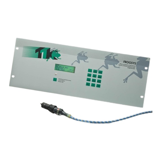
Digital unit
Hide thumbs
Also See for FG-SYS:
- Quick start manual (2 pages) ,
- Quick start manual (2 pages) ,
- Quick start manual (2 pages)

Related Manuals for TTK FG-SYS


Summary of Contents for TTK FG-SYS
- Page 1 FG-SYS DIGITAL UNIT INSTALLATION GUIDE June 2014 – Version 3.0 FG-SYS Products FG-SYS_Inst_guide_UK_062014.doc...
- Page 2 The information contained in this document can be the subject to modifications without notice. This information and diagrams were drawn up carefully, however TTK UK Ltd., TTK Asia Ltd. or TTK S.A.S. cannot guarantee that the provided information does not contain any error or omission and cannot accept any comparative responsibility with which the information is used.
-
Page 3: Table Of Contents
2.2. Precaution for use and storage 2.3. Addition of sense cables on an existing circuit 2.4. Addition of a new circuit of sense cables 3. Trouble Shooting Guide APPENDIX Connection of Digital Unit FG-SYS E or FG-SYS F (Wall or Rack version) -
Page 4: Atex Certificate
Report/ratio of tests n°01410051446 FG-SYS F: Certificate n° Al 00 08 28525 003 FG-SYS E: Certificate n° B 00 08 28525 004, dated on 08-10-2000 Bauart (B = Bauart) - Gs (Al = Gs) TÜV Product Service GmbH Mergenthalerallee 27, D - 65760 Eschborn – Germany - EU Functional Test Certificate Functional tests of FG-SYS, Liquid Leak Detection and location System, according to Test Report n°... - Page 5 IXING THE IGITAL Digital Unit FG-SYS E is used in Rack Mounted Version, in a bay or a cupboard 19 '''. It is advised to envisage a site with height of the eyes to facilitate the reading of the display.
-
Page 6: Connection Of The Fg-Sys Digital Unit To The Earth
Connections are done on the electronic board of the digital unit. The connector blocks are directly accessible and removable (male parts) on the FG-SYSF and E; for the FG-SYS F (metal enclosure wall mounted version), it is necessary to turn the key button of the front face to open it. - Page 7 (See Appendix n°1: FG-SYS E or F Digital Unit Connection page 57, and also available separately inside the unit) Each circuit of sense cables is connected to the FG-SYS Digital Unit with a TTK Leader Cable (Belden 8723), ref. FG-CLC Caution: An inversion between the two couples red + black, and green + white, damages the electronic of the first connected sense cable.
-
Page 8: Connection Of The Relays
3.6 Closing the FG-SYS F Digital Unit All connections being finished, close the FG-SYS F Digital Unit. Fix the part of the unit containing the circuit board on the part fixed at the wall. Be careful to the various cables connected and the flat ribbons during closing the front door. - Page 9 II SENSE CABLE AND ACCESSORIES INSTALLATION FG-SYS System is modular. All the sense cables and accessories are pre-terminated with both male and female connectors. This makes the installation quick, easy, and safe. We recommend drawing a precise map of all zones to be fitted with sense cables, ensuring that all installation zones are clean and dry before installation.
-
Page 10: Sense Cable Installation
6. FG-OD kit installation instructions CAUTION: All hydrocarbon sense cables must be installed in dry and clean areas On the basis of the FG-SYS Digital Unit, unroll the lengths of sense cable while placing them in the clips fixed on the ground. - Page 11 To connect the FG-SYS Digital Unit, follow the FG-SYS installation instructions guide in chapter 1.3 of this document. FG-SYS haves a capacity of 40x FG-OD cables per circuit. Those cables must be connected to the panel through a FG-DOD bus interface by groups of ten cables maximum.
- Page 12 1.4 Labeling with ES-EC tags Labels ES-EC indicate the presence of sense cables installed. Part of the label is reserved to the user to note the distance rose, during water leak simulations. 1. Fix the labels every four meters on the circuit of sense cables. 2.
- Page 13 BELDEN 8723 (LSZH, if required) This jumper cable must be equipped with a male and female connector, in order to be compatible with the TTK sense cables. The FG-NC Kit includes for this purpose the following material: A male connector with its 4 contacts ...
- Page 14 Jumper Cable BELDEN 8723 Crimp a male contact on each of the four wires. The wire of shielding is to be crimped in the same contact as the black wire. Jumper Cable BELDEN 8723 4 Male Contacts - Put a 45 mm Heat Shrinkable Tube on the Jumper Cable. 45 mm Heat Shrinkable Tube Male Contacts...
- Page 15 Prepare the Male Connector (the longest). Encase the 4 contacts in the connector, Draw the red plate while pressing on the sides (It is normal that it entirely did not leave). Male Connector The red plate left Press and Draw Insert the four contacts then, by respecting the following code: Red Wire : point n°1 of Male Connector...
- Page 16 Male Connector 45 mm Heat Shrinkable Tube Cover connections and the screw pitch with the 45 mm Heat Shrinkable tube, slipped beforehand on the jumper cable. Place a ring of adhesive (Hot melt) at the rear of the tube, side cable. Jumper Cable BELDEN 8723 Hot Melt 45 mm Heat Shrinkable Tube...
- Page 17 Let cool the Tube in driving position, connector downward. Proceed in the same way for the other end with a Female Connector and Female Contacts. DO NOT CONNECT THE WIRE OF SHIELDING: Green White Black 45 mm Heat Shrinkable Tube Female Connector Female Contacts The Red Plate and the...
- Page 18 The diagram of the finished Jumper Cable is the following: BELDEN 8723 Female Connector Male Connector Heat Shrinkable Tube Heat Shrinkable Tube Hot melt Ring...
-
Page 19: Accessories Installation
In the last Sector Diversion Box, We must end with a shunt in OUTPUT in the circuit board, between A and B. Installation of the FG-DTCS Diversion box must be done when the FG-SYS Digital Unit is switched off. INPUT corresponds to the Belden cable coming from the FG-SYS Digital Unit OUTPUT corresponds to the Belden cable leaving towards the following Diversion Box FG-ECS corresponds to the FG-ECS sense cable. - Page 20 In the last FG-DCTL addressable box, the circuit must be completed with a shunt in the OUTPUT of the circuit board (between A and B). The INPUT is linked to the Belden cable coming from the FG-SYS Digital Unit, or from the previous FG-DCTL addressable box The OUTPUT is linked to the Belden cable leaving towards the next FG-DCTL addressable box The SENSOR output is linked to the FG-ECS, FG-ACS, FG-ECX or FG-ACX sense cable.
-
Page 21: Fg-Dtc, Ttk Bus Diversion
3.3 FG-DTC, TTK Bus Diversion The TTK Bus Diversion box makes it possible to break up a detection circuit into two parts. The box is provided with three cable glands: ‘INPUT’, ‘OUTPUT2’ and ‘‘OUTPUT1’. FG-DTC Diversion Box Diagram: INPUT OUTPUT2... - Page 22 See below for instructions on how to connect the FG-OD cables to the main bus wire. The INPUT is linked to the Belden cable coming from the FG-SYS Digital Unit, or from a previous box OD BUS is linked to the FG-OD sense cables (10x max per FG-DOD box) OUTPUT corresponds to the Belden cable towards the end of the circuit.
-
Page 23: End Termination Plug
3.5 End Termination Plug 3.5.1. FG-TMC End Termination Plug (Use Only with FG-EC or FG-AC Sense Cables) Each circuit of sense cable must be end with an End Termination Plug. FG-TMC is used for the circuit continuity. 3.5.2. FG-TMX End Termination Plug (Use Only with FG-ECX or FG-ACX Sense Cable) 3.5.3. -
Page 24: Powering Of The Fg-Sys Digital Unit
When all of the cables - leader cables, jumper cables, sense cables, power supply cables - and the accessories – diversion boxes, end termination plugs- are connected, switch the FG-SYS Digital Unit When the digital unit is turned on, it goes into TEST mode: an audible alarm sounds and a luminous witness glows red. -
Page 26: Standby Mode
2. STANDBY MODE The Configuration Menu - accessible via the letter [M] - is used to set the parameters of the digital unit. To access it, you must enter your secret code. The factory access code is: 1234. You can change it in this menu. MENU CONFIGURATION 1-DESIGNATIONS 2-OPERATION... - Page 27 Example: four 15 m cables are associated to form a group of 60 metres. In the event of a leak detected by the third cable of the group, the alarms will be located between 31 m and 45 m instead of between 1 m and 15 m.
- Page 28 The screen then proposes the discontinuity synthesis, for which the relay number will necessarily be the same as for the leak synthesis. Re-confirm using the V button. The digital unit screen returns to the previous menu. Press the right arrow button to configure a relay linked to alarms on cable 001. Choose a relay number for the leaks and confirm.
- Page 29 Relays Wiring Diagram: REMOTE ALARM INDICATOR (2 SEPARATE INDICATORS) FG-A or FG-SYS unit LEAK RELAY CABLE BREAK CONTACT (N.O.) RELAY CONTACT (N.O.) LEAK CABLE BREAK INDICATOR INDICATOR POWER POWER SUPPLY SUPPLY 24V, for ex. 24V, for ex. REMOTE ALARM INDICATOR...
- Page 30 (These applications were not evaluated by UL) Supervisor Relay Contact Always N.C. Supervisor input for volt-free dry contact FG-SYS general relay terminal connector POWER RELAY CONNECTIONS FG-A or FG-SYS Unit RELAY CONTACT (N.O.) Power Transformer EXTERNAL POWER POWER DEVICE RELAY (SOLENOID VALVE, ETC.)
- Page 31 3 1 SLAVE NUMBERS: (01 - 99) 1 (M) 2.3.1.1 The FG-SYS digital unit is equipped with two independent serial interfaces. Each interface can be used, either: With RS232, three-wire connection: ...
- Page 32 (M) 3 SYSTEM PARAMETERS This sub-menu allows you to choose the language used, to initialize the time and date, and to set a password for access to the configuration system. All these parameters are kept in memory when the digital unit is turned off. (M) 3.1 LANGUAGES SYSTEM PARAMETERS LANGUAGES:...
-
Page 33: Communication Configuration
The communication is always point-to-point, type question-answer, with only one device using the connexion line at a time. The user of our FG-SYS Digital Unit could configure slave numbers from 1 to 99 and thus the simultaneous connexion of several central units to existing communication line is easy and very simple to do. - Page 34 3.2. Electrical connexions: 3.2.1 RS232 For One Single FG-SYS Digital Unit (max 100m): PC serial port 1 FG-SYS Digital Unit RS232 2 (Rx) 3 (Tx) 5 (GND) RS232 cable 3.2.2 RS422 For Several FG-SYS Digital Units (max 1200m): PC serial port 1 RS232/RS422 Converter FG-SYS Unit N°1...
- Page 35 For a single FG-SYS detection unit: 4.9. DB9 RS232 serial cable between the FG-SYS and PC For several FG-SYS detection units or when the distance between the PC and the FG-SYS detection unit is greater than 100 meters: 4.10. RS232/RS422 or RS485 converter 4.11.
- Page 36 The polarisation of communication lines from RS422/485 must be ensured by the supervisor. It is recommended to provide a break of at least 500 mms between JBUS polls. Caution! The simultaneous use of RS232 and RS422/485 interfaces causes the serial interface of the FG-SYS Digital Unit to power down.
- Page 37 7207). Tips: An Excel table (ready to complete), and incorporating all this information, is available on TTK website. The 'auto control’ file contains a PDF file listing all sense cables connected to the system, as well as their names, lengths, states, and other useful information.
- Page 38 Remove the SD card from the unit, read it using a PC and copy the necessary files (do not delete files) and then return the card to the unit. The entire unit’s information, loaded to its maximum capacity, is searchable using only 10 queries: 1.
- Page 40 Cablebreak in first area (Data Centre) The sound alarm could be annulated by the press button Alarm Sound - OFF appearing on the driver window. If an alarm disappears, the software will emit a very short sound and the corresponding red light alarm will pass to a normal, «...
- Page 41 The cables in alarm status are drawn in red and the normal status cables are in blue. A small graphic window simulating the central unit display is seen just next to each sense cable in alarm status. The maps are real-time information about a particular zone; each new event updates the information on the corresponding window.
- Page 42 IV TEST PROCEDURE All the material was installed; you have just turned the FG-SYS digital unit on, it is now necessary to test the system. 1. FUNCTION TEST The digital unit automatically carries out a general test during the powering of the system. This function TEST is also available from the MONITORING mode by pressing the key [T].
-
Page 43: Test Of Leaks
2. TEST OF LEAK The digital unit is in monitoring mode. Simulate in several areas a leak, in order to check the correct operation of the digital unit. The accuracy of the localization is ± 1 metre to the leak. Caution: A fault must be present for at least 30/40 seconds before being detected by the digital unit. - Page 44 The drawing identifies a series of simulated leaks; the localization of these leaks is displayed on the FG-SYS Digital Unit. Make a simulation at the remote end of all the sense cables on the circuit. Precisely note the localization given by the digital unit displayed on the LCD Digital Unit. It is easier to carry out these simulations with a suitable tool of communication (transmitting - receiver).
-
Page 46: Checking The System
2.3 Addition of Sense Cables on an Existing Circuit An extension of the FG-SYS Digital Unit implies either an addition of sense cables on a circuit of existing cables (maximum capacity of 40 sense cables per circuit,) or the installation of a new circuit of... -
Page 47: Addition Of A New Circuit Of Sense Cables
Cable break bus: Check the connection between the leader cable FG-CLC and the connector block on the FG-SYS Digital Unit. A short-circuit between the red wire and the black wire can cause cable break alarm. - Page 48 FG-SYS Digital Unit " blocked ": Make a «Test ", by pressing on the “ T “ key, on the front keypad. If after one minute, the FG-SYS Digital Unit is still blocked, turn the Digital Unit off, for at least three minutes, and then turn it on. If still...
Need help?
Do you have a question about the FG-SYS and is the answer not in the manual?
Questions and answers