Table of Contents
Advertisement
Advertisement
Table of Contents

Related Manuals for LX Navigation LX 7007 C


Summary of Contents for LX Navigation LX 7007 C
- Page 1 LX Navigation d.o.o. LX 7007 C May. 30th 2012 LX 7007 C Users manual V 3.0 (Also valid for LX 7007 CB and LX 7007 Compact C/CB) LX navigation d.o.o. Tkalska 10 SLO 3000 Celje + 386 3 490 46 70 + 386 3 490 46 71 support@lxnavigation.si...
-
Page 2: Table Of Contents
LX Navigation d.o.o. LX 7007 C May. 30th 2012 GENERAL........................- 5 - Technical data............................- 6 - Options ..............................- 7 - 1.2.1 Two seater configuration........................- 7 - 1.2.2 Remote control ..........................- 7 - 1.2.3 Flarm ..............................- 7 - LX 7007 Compact C and LX 7007 Compact CB ................ - Page 3 Final glide calculation........................- 32 - 2.5.4.1 Final glide after using of FAI finish setting ................- 32 - FLYING WITH THE LX 7007 C..................- 33 - Flight preparation on ground ......................- 33 - 3.1.1 Single pilot option..........................- 33 - 3.1.2...
- Page 4 LX Navigation d.o.o. LX 7007 C May. 30th 2012 4.8..................................- 46 - 4.8.1 Wiring LX 7007 Compact C......................- 46 - 4.8.1.1 GPS connection........................- 47 - 4.8.2 Wiring LX 7007 Compact C B ......................- 47 - 4.8.2.1 GPS connection........................
-
Page 5: General
LX 7007 CB The unit comes in two versions LX 7007 C can be fitted into 80 mm standard cut out and LX 7007 CB has a bigger (3.5 inch) display which requires a larger cut-out. The functions of both units are identical. -
Page 6: Technical Data
LX Navigation d.o.o. LX 7007 C May. 30th 2012 Navigation functions include: Airport and airspace database for Europe or USA, an almost unlimited number of AS sections can be • stored Turn points in .cup format, an almost unlimited number of files can be stored, up to three active files can be •... -
Page 7: Remote Control
-external GPS input plug and play compatible with Colibri, LX 20, Colibri II, Flarm) -vario electronics built into main unit (not valid for CB) Unit operation is almost the same as the LX 7007 C, so the same manual can be used. Functions that are different are marked. -
Page 8: System Description
LX Navigation d.o.o. LX 7007 C May. 30th 2012 2 System description Rotary switches and keys (buttons) The following controls are mounted on the front face of the LX7007 C Four rotary selector switches • Six push buttons • Mode selector Audio adj. -
Page 9: Mode Selector (Rotary Switch)
LX Navigation d.o.o. LX 7007 C May. 30th 2012 2.1.2 MODE selector (rotary switch) The mode selector is used to change modes of operation. This switch has the highest priority in the system. Whenever it is operated, a mode change will occur. -
Page 10: Operating Modes
LX Navigation d.o.o. LX 7007 C May. 30th 2012 Operating modes MODE Near airport Airport Turnpoint Task Log book / statistics Setup Navigation menus (APT, TP and TSK) have sub menus, which can be selected using the Up/Down rotary switch. -
Page 11: Setup
System which allows entry into system setup. Note! TRANSFER offers no inputs, but enables data transfer LX 7007 C to SD Card, PDA, Colibri or PC. Once the desired option has been selected, press ENTER to access the sub-menu. -
Page 12: Pilot
LX Navigation d.o.o. LX 7007 C May. 30th 2012 QNH: Initial status after power on is undefined (- - - - - ). If the pilot wants to adjust the altitude reading due to pressure changes during the flight, then an initial input of the actual QNH is required. Input is done with Up/Down and ZOOM. - Page 13 • The LX 7007 C has a connection for an external speed command switch, which is wired to LX 7007 vario unit. Using an external switch it is possible to switch between SC and Vario manually. Setting the SC Switch to ON means that closing of the switch will cause SC mode, and setting SC INPUT to OFF means that closing the switch will select Vario mode.
-
Page 14: Transfer
TRANSFER Transfer makes it possible to input Turn point data, Airport data and Airspace data into LX 7007 C. The files should be copied to an SD card by PC.TP files format should be .cup, airspace .cub and airports in .af format. -
Page 15: System Setup (Second Level)
Input of Warning Yes will produce an audio warning close to the airspace. See also chapter Graphic/Appearance. Note! LX 7007 C is able to use only one airspace section at the same time, the section should be enabled in Airspace menu of System Setup, also during the flight. Creation of custom airspace files To prepare custom airspace, in .CUB format, use our special tool for airspace creation and edit, called... -
Page 16: Audio Alarm
LX Navigation d.o.o. LX 7007 C May. 30th 2012 SC: VOL H audio volume will be increased or decreased during speed command period set (H) or ( L) • tone frequency at 0 m/s • +100%: tone frequency at full + deflection •... -
Page 17: Task Observation Zone
(zone) of Task navigation menu. 2.3.2.7 Graphics The graphic display of the LX 7007 C can show a lot of information and if it is all selected, the display can become very cluttered. This particularly applies to airspace information and the user should ensure that only relevant airspace is selected. -
Page 18: Lx Navigation D.o.o. Lx 7007 C May. 30Th
LX Navigation d.o.o. LX 7007 C May. 30th 2012 point out that the figure is not a fixed altitude but is connected to glider actual altitude. Setting 1000m means that particular AS section which level is 1000m higher than glider actual altitude will not be shown. -
Page 19: Te Comp
TE comp. 2.3.2.8 LX 7007 C has the capability to offer variometer total energy compensation in two ways. Selection of compensation method is done after selection the % figure. 000% means total energy compensation when using a TE tube. When using this solution the unit does not process compensation this depends entirely on the TE tube and its installation. -
Page 20: Units
After indicator functions have been defined, switch the unit off and then on again, this procedure will memorize the settings. 2.3.2.11 Units All known units and combinations can be programmed in the LX 7007 C. The various units that can be selected are outlined below: - 20 -... -
Page 21: Voice
Celsius or Fahrenheit • 2.3.2.12 Voice If Voice module is connected to LX 7007 C (connection via 485 bus) following settings will settle Voice module operation. Checked items means active function and vice versa. Flarm part is relevant only if the unit is equipped with Flarm option. -
Page 22: User Port
User port is a stand alone RS 232 standard port which is capable to deliver NMEA sentences to third party units connected to LX 7007 C. The port can be used to supply GPS data for transponder. Most common used baud rates are available. -
Page 23: Firmware Update
The password is therefore valid only for particular unit. LX 7007 C FW update procedure: -check actual program version status and creation date in Setup About -switch the unit off -insert SD card which includes new file (update.LX7) -
Page 24: Navigation Functions
LX Navigation d.o.o. LX 7007 C May. 30th 2012 Navigation Functions The LX 7007 C has following navigation functions displayed on six main pages. The pages are selected in sequence by rotating the MODE ( ) selector: GPS - Status and Coordinates •... -
Page 25: Apt Airports, Tp Turn Points
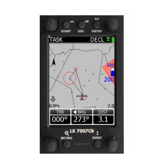
LX Navigation d.o.o. LX 7007 C May. 30th 2012 2.4.3 APT Airports, TP Turn Points Both navigation modes (APT, TP) are selectable by rotating the MODE selector. The functions carried out are more or less similar and that’s the reason of concentrated description. Basic page is graphic page where you will find initial navigation data and also graphic display which includes airspace data. -
Page 26: Airport Selection
Wait 1 or 2 indicates wind calculation is in progress. *** Thermal assistant helps when climbing to find the centre of the thermal, see also capture Flying LX 7007 C. **** Altitude gain (AG) collected during climbing in existent thermal will be displayed when climbing and Total average (LTAvg) reached in the last thermal will be displayed during straight flight. -
Page 27: Turn Point Selection
LX 7007 C memory and defined as active (Syst. Setup/Turn points) There are three stores for task data in LX 7007 C memory. First is called User (USR xx) and there are stored tasks created by hand (Maximum 70 tasks). - Page 28 LX Navigation d.o.o. LX 7007 C May. 30th 2012 How to edit task data? At any point the task (IMP, USR or Declared) can be edited. Simply put cursor to the point of interest press enter and edit menu will open. Use Select, Insert and Delete options.
- Page 29 LX Navigation d.o.o. LX 7007 C May. 30th 2012 Task Start Task start has been optimised by loading the pilot during the start procedure keeping work load as low as possible. The unit is capable of recognising when the Start line is crossed and to change over to first point automatically.
-
Page 30: Statistics
2.4.5 Statistics Statistics is a stand alone mode of LX 7007 C and logically positioned near task mode. In general there are two levels of statistics, flight statistics and task statistics. Flight statistics is available during every flight and the task statistics can be called exclusively after a task has been started. -
Page 31: Variometer And Altimeter
LX Navigation d.o.o. LX 7007 C May. 30th 2012 Variometer and altimeter All signals from the pneumatic sensors (altitude, speed) are derived from high quality digital pressure sensors which mean that no flask is necessary. The vario signal is derived from the altitude signal. All signals are temperature and altitude compensated. -
Page 32: Altimeter
May. 30th 2012 2.5.2 Altimeter The altimeter of LX 7007 C is temperature compensated from -20ºC up to + 60ºC. The altimeter is calibrated from 0 to 6000m (20,000ft), but indication goes up to 8000m (26,000ft). Important! After correct field elevation input the altimeter indication will always be MSL (Mean sea Level). -
Page 33: Flying With The Lx 7007 C
If only one person fly’s the glider, then only his name should be programmed into the instrument through FLIGHT INFO. The LX 7007 C will then show the name of the pilot during the initialisation procedure and switch automatically to the Set Elevation page. Don’t confirm SAVE TO PILOT LIST with Y. -
Page 34: Preparation Of Data Base
SD card. 1. prepare files (TP or Airspace) on PC and copy to SD card 2. use Transfer to copy from SD card into LX 7007 C 3. enable files of interest in System setup/turn points or Airspace 3.1.5... -
Page 35: Task Start
Task Start Task start is a complex procedure, as this action includes tactical elements and also technical criteria which must be respected due to rules. LX 7007 C start support will help both before start and also during start. Particularly useful is the Limitations menu where all the most important parameters can be preset. -
Page 36: Flarm Functions
Using the Flarm functions, which are available on LX 7007 C graphic display, doesn’t suspend the use of Flarm external indicator. There are two displays which show Flarm data on LX 7007. Flarm objects are shown in graphic page as glider symbols and also so called “Flarm radar”, can be activated. -
Page 37: Flarm "Traffic Radar
LX Navigation d.o.o. LX 7007 C May. 30th 2012 3.3.2 Flarm “Traffic Radar” This function is exclusively achieved on pilot demand. A short press on Event button opens so called Flarm Radar page. The page consist of glider symbol which is centrally positioned, concentric circles with two possible info boxes. -
Page 38: Airspace Monitoring During Flight
LX Navigation d.o.o. LX 7007 C May. 30th 2012 3.3.3 Airspace monitoring during flight LX 7007 Computer permanently monitors all airspace sections in the vicinity. If the glider position becomes close enough, an info row in the upper part of the display become active. Both vertical and horizontal distances are respected by calculation. -
Page 39: Airspace Management
LX Navigation d.o.o. LX 7007 C May. 30th 2012 Airspace Management 3.3.3.1 A long press on Enter (in graphic only) will open a list of all airspace sections which are close to the glider. The pilot is now able to select some restrictions or to disable particular airspace permanently. -
Page 40: Installation
LX Navigation d.o.o. LX 7007 C May. 30th 2012 4 Installation Mechanical layout Vario Main unit °80.0mmh11 °89.0mm Main unit installation template Installation of main unit Prepare the cut-out in the instrument panel According to the drilling template. Remove the press-in covers from the four main selectors on the LX 7007 PRO IGC. -
Page 41: Pneumatic Connections
LX Navigation d.o.o. LX 7007 C May. 30th 2012 instrument panel selector axis special type screw LX7007 LX5000 press-in cover rotary knob Pneumatic connections Three pressure connectors are fitted to the back of the vario unit. A label shows their functions. -
Page 42: Power Connection
LX Navigation d.o.o. LX 7007 C May. 30th 2012 TE tube installation schematics (Set TE 000%) TE/Pst TE tube Static Ptot Pitot or Total pressure Note! If the Ptot and Static are connected the wrong way around, there will be no integrator reading (average climb) during the flight. -
Page 43: Vario/Sc External Switch Installation
Installation of PDA units LX navigation offers a wide range of accessories which makes the installation of a PDA in conjunction with LX 7007 extremely easy and completely plug and play. LX 7007 has a separate com port specially designed to drive PDA, 5V power for PDA is included. -
Page 44: Installation Of Options
LX 7007 C DU also powers all bus connected devices. A fuse built on LX 7007 C DU back prevents damage to the DU after a short in wiring or in some 485 device will happen. -
Page 45: Wiring Schematics (Also Valid For Lx 7007 Compact Cb)
LX Navigation d.o.o. LX 7007 C May. 30th 2012 Wiring schematics (also valid for LX 7007 Compact CB) - 45 -... -
Page 46: Wiring Lx 7007 Compact C
4.8.1 Wiring LX 7007 Compact C LX 7007 Compact wiring differs from wiring used in LX 7007 C, LX 7007 CB and LX 7007 Compact CB models. Only one 24 p connector is positioned on the back side of the unit. Inputs and outputs are already wired and also clearly marked. -
Page 47: Gps Connection
IGC specification will used. 4.8.2 Wiring LX 7007 Compact C B The unit has standard LX 7007 C connector layout, the same is also wiring. GPS connection 4.8.2.1 GPS connection is realized via 8P telephone type connector which positioned on the back of the unit. Connector specifiactio meets IGC standard, so refer 4.8.8.1 for details.
Need help?
Do you have a question about the LX 7007 C and is the answer not in the manual?
Questions and answers