Table of Contents
Advertisement
®
Installation, Operation and Maintenance Manual
Please read and save these instructions for future reference. Read carefully before attempting to assemble,
install, operate or maintain the product described. Protect yourself and others by observing all safety
information. Failure to comply with instructions could result in personal injury and/or property damage!
Model RV/RVE
General Safety Information
moving parts, as well as other potential hazards. Other
forward.
4. Do not spin wheel faster than maximum cataloged
not exceeding the motor nameplate amps.
equipment.
6. Never open access doors to the unit while it is
running.
®
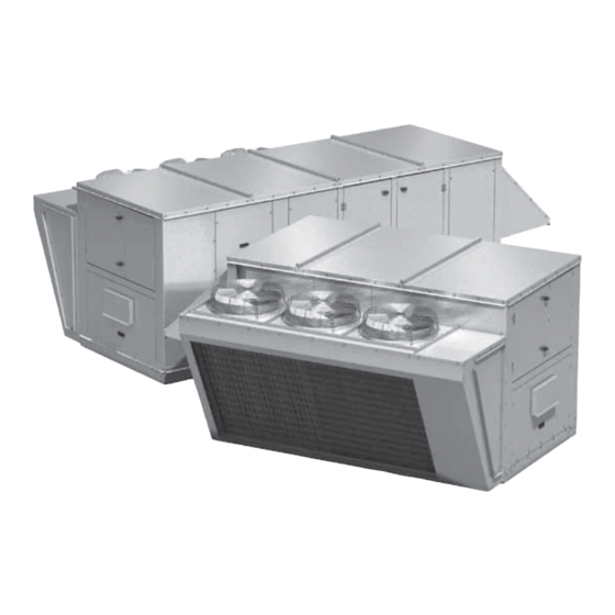
Packaged Rooftop Ventilator
WARNING
The roof lining contains high voltage wiring. To
prevent electrocution, do not puncture the interior or
exterior panels of the roof.
DANGER
CAUTION
This unit is equipped with a compressed refrigerant
harm.
CAUTION
Part #474612
RV/RVE
Packaged Rooftop Ventilator
1
Advertisement
Table of Contents

Related Manuals for Greenheck RV-35


Summary of Contents for Greenheck RV-35
-
Page 1: General Safety Information
Part #474612 RV/RVE ® Packaged Rooftop Ventilator Installation, Operation and Maintenance Manual Please read and save these instructions for future reference. Read carefully before attempting to assemble, install, operate or maintain the product described. Protect yourself and others by observing all safety information. -
Page 2: Receiving, Handling, Storage
Receiving hard to reach internal surfaces or for occasional use, or the equivalent. Product Overview and/or heating. The unit is designed to replace air that Unpacking as an option. Cooling Handling Heating There are three different optional heat sources that can heat exchangers Storage Airflow Arrangement... -
Page 3: Table Of Contents
Table of Contents General Safety Information ....1 Factory-Installed Refrigeration System Components ......13 Receiving, Handling, Storage . -
Page 4: Subassemblies
Subassemblies Blower Filters Coils Final Filters. Indirect Gas-Fired Furnace Compressors Packaged DX System Dampers designed for other refrigerants on these units. Optional Barometric Relief Damper Split DX pressure increases, relief damper will open due to over pressurization. Vestibule Electric Heater wiring diagram. -
Page 5: Installation
Indirect Gas Damper Heater Unit Unit Final Filter Outdoor Air Condensing Optional Size Weight Size Length Width Height Weatherhood Section Piping Vestibule RV-35 21.5 95.6 52.5 28.8 26.0 58.2 2,600 20x20 RV-50 21.5 108.8 64.0 32.0 26.0 70.5 3,600 20x25 RV-80 26.5... -
Page 6: Lifting
Lifting Additional Clearances for Packaged DX Units 2. To assist in determining rigging requirements, weights are provided in the Unit Weights & Dimensions section of this manual. avoid recirculation or coil starvation. When equipped of unit. Use spreader bars to prevent damage to cabinet. Minimum 48 inches clearance Condenser Fans Minimum 42 inches... - Page 7 Roof Curb Mounting Optional Piping Vestibule instructions. 1. Factory Supplied Roof Curbs 2. Install Curb coil drainage and unit operation, it is important that the 3. Install Ductwork Typical Unit with Piping Vestibule and Factory-Supplied Curb Kit provided to support ducts prior to setting the unit. 4.
-
Page 8: Recommended Electrical And Gas Supply Entry Locations
Rail Mounting and Layout location and ensure the use of an alternate location handle the weight of the unit and provide proper load does not interfere with unit wiring, components or the openings on the unit. WARNING Never drill holes in the roof of the unit! There is high roof panels. -
Page 9: Electrical Information
Electrical Information Determine the Size of Electric Heater WARNING Wiring The roof lining contains high voltage wiring. To prevent electrocution, do not puncture the interior or exterior panels of the roof. WARNING sizing. open. Provide the Opening(s) for the Electrical Connections IMPORTANT understand the following instructions and wiring... -
Page 10: Plumbing / Piping Overview
Plumbing / Piping Overview Split DX / Water Coil Connections Condensate Drain Trap This unit is equipped with a stainless steel condensate proper drainage of condensate while maintaining internal static pressures and to prevent into the unit. supplied with each unit and is to and area codes require a permanent drain line, it should trap and drain line of metal and install a heat tape to prevent freezing. -
Page 11: Control Center Components
Control Center Components Optional Indirect Gas-Fired Furnace Main Control Center Components High Voltage Side 4. VFD provide greater output. When two furnaces are installed, identical controls. 7. Transformer Low Voltage Side 6. Transformer For further information on the optional furnace and its shipped with the unit. -
Page 12: Component Operation
Component Operation Phase Monitor Supply Fan VFD Sequence Optional Room CO2 Sensor: and when it detects a fault, it Optional Duct Static Pressure Sensor: the low voltage terminal strip, Typical Phase Monitor comparison of the duct static pressure set point to the actual duct static pressure level reported from Variable Frequency Drive (VFD) for optimum performance. -
Page 13: Factory-Installed Refrigeration System Components
Factory-Installed Refrigeration System Components Circuit A Condenser Coil Check Valve 1. Thermostatic Expansion Valve (TXV) 10. Hot Gas Bypass Valve (optional) Valve on each refrigerant circuit. The valve controls Valve Adjustment - entering air to the evaporator coil. The valve should through the coil panel access door. -
Page 14: Start-Up Unit
Start-Up Unit DANGER WARNING for 24 hours without a call for cool to allow the maintenance, turn the electrical power to unit to OFF liquid refrigerant present in the compressor. power supplies. CAUTION Use caution when removing access panels or other CAUTION ensure safe and proper practices are followed. - Page 15 Pre-Start-Up Checklist SPECIAL TOOLS REQUIRED unit. accessories for tightness. Start- Up Procedure collected while the unit is running. connections. wheel. compressors are rotating the correct direction. Voltage Imbalance measurements in this formula. compressor which needs power supplied to it 24 energize unit.
- Page 16 Start-Up Checklist Line Voltage. Check at unit disconnect. Volts Volts Volts Motor Amp Draw Fan RPM Correct fan rotation direction? Yes / No Yes / No Energy Wheel Motor Condensing Fans Compressors Outdoor Air Temperature Deg F Outdoor Air Relative Humidity Return Air Temperature Deg F Return Air Relative Humidity...
-
Page 17: Start-Up Components Fan
Start-Up Components Supply/Exhaust Fan CAUTION amperage rating shown on the motor nameplate when manufacturer to determine if the unit can operate installed except the control center door. Supply Fan (Plenum Type) Vibration or component failure. The most common sources of offset. -
Page 18: Optional Energy Wheel
Optional Energy Wheel Sequence of Operation Start-Up Optional Economizer Stop Wheel: and there is a signal for cooling, the wheel will stop rotating to allow free cooling. Idle Wheel: there is a signal for cooling, the wheel will rotate at Retaining Screws Adjustable... -
Page 19: Optional Energy Wheel
Optional Energy Wheel Maintenance Cleaning WARNING Whenever performing maintenance or inspections, the wheel cassette to avoid splashing liquids or Inspection accordance with the maintenance schedule. DISCOLORATION AND STAINING OF ENERGY RECOVERY WHEEL DOES NOT AFFECT ITS wheel for cleanliness and then PERFORMANCE. -
Page 20: Troubleshooting
– Optional Energy Wheel Troubleshooting Symptom Possible Cause Corrective Action does NOT Replace. turn No power to wheel motor. Wheel motor overloads are wheel runs wheel and air seals. Troubleshooting – Alarms Optional Digital Scroll Compressor Controller the unit or a single function within the unit. DDC Controller selected. -
Page 21: Unit
Troubleshooting – Unit Symptom Possible Cause Corrective Action Defective motor or capacitor. Replace. to operate or less. starters do not pull in anticipated. Voltage supplied to starter nominal voltage stated on the coil. supplied voltage. amps Replace motor. practices. required. Repair. - Page 22 Troubleshooting – Refrigeration Circuit TROUBLESHOOTING NOTE IMPORTANT required service procedures include the adding or removing of refrigerant, the service technician must this guide. Symptom Possible Cause Corrective Action Open disconnect switch or circuit Low line voltage. will not run or does not start or defective.
- Page 23 Troubleshooting – Refrigeration Circuit Symptom Possible Cause Corrective Action Refrigerant overcharge. cuts out on high pressure expansion valves. switch Defective high pressure switch. Replace. High pressure Restriction in discharge or liquid line. activates at 600 PSIG Replace. Low voltage. cuts out Defective compressor overload.
- Page 24 Troubleshooting – Refrigeration Circuit Symptom Possible Cause Corrective Action secured to suction line. pressure Thermostatic expansion valve. Overfeeding. Replace expansion valve power head. Room load too large. Reduce the load or add more equipment. Overcharged. Thermal expansion valve setting. Too much refrigerant. discharge pressure controls.
- Page 25 Troubleshooting – Refrigeration Circuit Symptom Possible Cause Corrective Action refrigerant. expansion valve. discharge pressure Low suction pressure. condensing temperature. Thermostat location or controls malfunction. Defective high or low pressure control. loses oil operation. Refrigeration undercharged. Not enough cooling outdoor temperature. cooling Restriction in suction and liquid line.
-
Page 26: Routine Maintenance
Routine Maintenance Maintenance Frequency: Monthly DANGER maintenance, turn the electrical power to the unit to power supplies. CAUTION Semiannually Use caution when removing access panels or other motor manufacturer’s recommendations. This unit requires minimal maintenance to operate Annually maintenance occur at the start of the cooling season. 2. -
Page 27: Gas Furnace
Maintenance Procedures: WARNING Lubrication REFER TO GENERAL SAFETY INFORMATION proper operation. Do not remove access panels or other unit Dampers components while standing on a ladder or other External Filter Maintenance ensure the actuator opens and closes the damper as designed. -
Page 28: Maintenance Log
_________________________________________________ _________________________________________________ _________________________________________________ Date ___________________Time _____________ Date ___________________Time _____________ ___________________________________________ ___________________________________________ _________________________________________________ _________________________________________________ _________________________________________________ _________________________________________________ _________________________________________________ _________________________________________________ _________________________________________________ _________________________________________________ Warranty As a result of our commitment to continuous improvement, Greenheck reserves the right to change specifications without notice. www.amca.org. ®...
Need help?
Do you have a question about the RV-35 and is the answer not in the manual?
Questions and answers