
Related Manuals for SEW movigear sni-b

Summary of Contents for SEW movigear sni-b
- Page 1 Drive Technology \ Drive Automation \ System Integration \ Services Operating Instructions Mechatronic Drive System ® MOVIGEAR SNI-B Single Line Network Installation Edition 12/2013 20254547 / EN...
- Page 2 SEW-EURODRIVE—Driving the world...
-
Page 3: Table Of Contents
Contents Contents General information .................... 6 How to use this documentation ..............6 Structure of the safety notes ............... 6 Rights to claim under warranty ..............7 Exclusion of liability..................7 Copyright..................... 7 Product names and trademarks ..............7 Safety notes......................8 General information .................. - Page 4 10.3 Switch-off responses ................178 10.4 Reset of error messages ..............178 10.5 Description of status and operating displays ........179 10.6 Error table ................... 182 10.7 Unit replacement ................. 184 10.8 SEW-EURODRIVE Service ..............186 Operating Instructions – MOVIGEAR® SNI-B...
- Page 5 Contents 10.9 Shutdown .................... 187 10.10 Storage ....................187 10.11 Extended storage..................188 10.12 Disposal ....................190 Inspection and maintenance................191 11.1 Determining the operating hours ............191 11.2 Inspection and maintenance intervals ..........192 11.3 Lubrication change intervals ..............193 11.4 Inspection and maintenance work ............
-
Page 6: General Information
If you are unclear about any of the information in this documentation, or if you require further information, contact SEW-EURODRIVE. Structure of the safety notes 1.2.1... -
Page 7: Rights To Claim Under Warranty
You must comply with the information contained in this documentation to ensure safe operation and to achieve the specified product characteristics and performance fea- tures. SEW-EURODRIVE assumes no liability for injury to persons or damage to equip- ment or property resulting from non-observance of these operating instructions. In such cases, any liability for defects is excluded. -
Page 8: Safety Notes
If you are unclear about any of the informa- tion in this documentation, or if you require further information, please contact SEW- EURODRIVE. -
Page 9: Designated Use
Safety notes Designated use Designated use ® MOVIGEAR drive units are components intended for installation in electrical systems or machines. ® In case of installation in machines, taking the MOVIGEAR drive units into operation (i.e. start of designated operation) is prohibited until it is determined that the machine meets the requirements stipulated in EC Directive 2006/42/EC (Machinery Directive). -
Page 10: Installation
Safety notes Installation Installation The units must be installed and cooled according to the regulations and specifications in the corresponding documentation. ® Protect the MOVIGEAR drive units from improper strain. The following applications are prohibited unless explicitly permitted: • Use in potentially explosive atmospheres. •... -
Page 11: Operation
Safety notes Operation Operation ® Systems with integrated MOVIGEAR drive units must be equipped with additional monitoring and protection devices according to the applicable safety guidelines, such as the law governing technical equipment, accident prevention regulations, etc. Additional protective measures may be necessary for applications with increased potential risk. ®... -
Page 12: Unit Structure
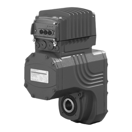
Unit structure ® MOVIGEAR drive unit Unit structure ® MOVIGEAR drive unit ® MOVIGEAR drive units are made up of 3 core components: gear unit, motor and drive electronics. These 3 core components are included in one die-cast aluminum housing (see following figure). -
Page 13: Shaft Types
Unit structure Shaft types Shaft types ® MOVIGEAR is available with the following shaft types: ® 3.2.1 MOVIGEAR with hollow shaft and keyway (MGFA..) ® The following figure shows a MOVIGEAR unit with hollow shaft and keyway: 18014401200302603 ® ® 3.2.2 MOVIGEAR with TorqLOC... -
Page 14: Housing Mounting
Unit structure Housing mounting Housing mounting 3.3.1 Torque arm (MGF.T) The following figure shows the torque arm for MGF.T: 18014401200308363 3.3.2 Housing with threads (MGF.S) The following figure shows the housing type with threads for mounting a torque arm. This type does not include a centering shoulder, which means it is not suitable for direct installation to the machine: 18014401200306443 Operating Instructions –... -
Page 15: Cable Entry Positions
Unit structure Cable entry positions Cable entry positions ® The following cable entries are possible for MOVIGEAR drive units: • Position X + 2 – X: 2 x M25 x 1.5 + 2 x M16 x 1.5 – 2: 2 x M25 x 1.5 + 2 x M16 x 1.5 •... -
Page 16: Example Nameplate And Type Designation Of The Drive Unit
Unit structure Example nameplate and type designation of the drive unit Example nameplate and type designation of the drive unit 3.5.1 Nameplate ® The following figure gives an example of a MOVIGEAR nameplate. For the structure of the type designation, refer to chapter "Type designation". 86,3 76646 Bruchsal/Germany eff%... -
Page 17: Electronics
Unit structure Electronics Electronics ® 3.6.1 MOVIGEAR electronics cover (inside) and connection box ® The following figure shows the connection box and the bottom side of the MOVIGEAR electronics cover: [10] [11] 2389525515 Nameplate of drive unit, see following detailed view 2584370315 Connection ring ®... - Page 18 Unit structure Electronics 3.6.2 Electronics cover (outside) The following figure shows the possible variants of the electronic cover using one frame size as an example: I V E I V E 18014400877430923 A Electronics cover without application slot B Electronics cover with application slot [1] LED displays [1] Assembly/disassembly handle [2] Retaining screws (4x)
-
Page 19: Application Options
Unit structure Application options Application options 3.7.1 GIO12B application option The following figure shows the GIO12B application option: I V E 9007201622841227 [1] Assembly/disassembly handle [2] Retaining screws (4x) [3] M12 plug connector for digital I/Os The following figure shows the position of the GIO12B nameplate: 18014401210968331 [1] Nameplate Operating Instructions –... - Page 20 Unit structure Application options 3.7.2 GIO13B application option The following figure shows the GIO13B application option: I V E 9007201839769867 [1] Assembly/disassembly handle [2] Retaining screws (4x) [3] M12 plug connector for digital/analog I/Os The following figure shows the DIP switches S1 to S3 of the GIO13B application option: 18014401245670283 [1] Nameplate Operating Instructions –...
-
Page 21: Example Nameplate And Type Designation Of Electronics
Unit structure Example nameplate and type designation of electronics Example nameplate and type designation of electronics 3.8.1 Nameplate ® The following figure gives an example of a MOVIGEAR nameplate. For the structure of the type designation, refer to chapter "Type designation". 9007201839835019 [1] Nameplate of connection unit [2] Nameplate of application option... - Page 22 Unit structure Example nameplate and type designation of electronics 3.8.3 Type designation of connection unit The following table shows the type designation of the connection unit: M G x B – SNI / DSP Connection unit option DSP = Electrodynamic ®...
-
Page 23: Movigear ® With Optional Design For Wet Areas (/Wa Option)
Unit structure ® MOVIGEAR with optional design for wet areas (/WA option) ® MOVIGEAR with optional design for wet areas (/WA option) INFORMATION Slight color differences are possible in the HP200 surface finish due to the treatment process (individual treatment of the components). ®... - Page 24 Cable glands made of stainless steel * = Mounting position M3 only possible after consultation with SEW-EURODRIVE The required screw fittings can be ordered from SEW-EURODRIVE. For an overview, refer to chapter "Op- tional metal screw fittings". Make sure to select plug seals that are compatible with the used cleaning agents...
-
Page 25: Mechanical Installation
Mechanical installation Installation notes Mechanical installation Installation notes INFORMATION Adhere to the safety notes during installation. WARNING ® Improper installation/disassembly of MOVIGEAR drive units and mount-on compo- nents. Risk of injury. • Adhere to the notes about installation and disassembly. •... -
Page 26: Installation Requirements
Mechanical installation Installation requirements Installation requirements Check that the following conditions have been met: ® • The entries on the nameplate of the MOVIGEAR unit match the voltage supply sys- tem. • The drive is undamaged (no damage caused by transportation or storage) •... -
Page 27: Setting Up The Drive Unit
Mechanical installation Setting up the drive unit Setting up the drive unit 4.4.1 Information • Clean the output shafts thoroughly to ensure they are free of anti-corrosion agents (use a commercially available solvent). Do not expose the bearings and sealing rings to the solvent –... - Page 28 Mechanical installation Setting up the drive unit 4.4.2 Electronics cover WARNING Burns caused by hot surfaces. Severe injuries. • Let the units cool down before touching them. NOTICE Loss of the guaranteed degree of protection. Possible damage to property. ® •...
- Page 29 Mechanical installation Setting up the drive unit Min. installation Note the minimum installation clearance (see following figure) required to install and clearance of remove the application options. application options 9007201604871563 Removing the The following figure shows how you can lever off the electronics cover in the intended electronics cover places.
- Page 30 Setting up the drive unit 4.4.5 Gear unit venting ® Drive units with Except for the M3 mounting position, SEW-EURODRIVE delivers all MOVIGEAR drive installed breather units ordered for a specific mounting position with a breather valve that is activated and valve installed according to the specific mounting position.
-
Page 31: Application Options
Mechanical installation Application options Application options WARNING Burns caused by hot surfaces. Severe injuries. • Let the units cool down before touching them. 4.5.1 Removing the application cover ® MOVIGEAR drive units with application slot in the electronics cover are delivered with an application cover as standard. - Page 32 Mechanical installation Application options Never use the application slot as a handle when the application cover or application option is not installed. 8751136395 4.5.2 Installing application options NOTICE Loss of the guaranteed degree of protection. Possible damage to property. • In disassembled condition, you have to protect the GIO13 application option from moisture, dust or foreign particles as there are openings for DIP switches.
- Page 33 Mechanical installation Application options 3. Secure the option with the 4 retaining screws. The permitted tightening torque for the retaining screws is 1.4 - 1.6 Nm. I V E 27021600114606731 4. Use the provided screw plugs to seal the connectors that are not in use. The permit- ted tightening torque is: •...
-
Page 34: Shaft-Mounted Gear Unit With Keyway
Mechanical installation Shaft-mounted gear unit with keyway Shaft-mounted gear unit with keyway INFORMATION Observe the design notes in chapter "Technical data and dimension sheets" for the customer shaft design. 4.6.1 Installation notes ® 1. Apply NOCO-FLUID and spread it thoroughly. 9007201603382283 9007201603384203 Operating Instructions –... - Page 35 [1] Short retaining bolt (standard delivery scope) [2] Lock washer [3] Washer [4] Retaining ring [6] Customer shaft 2 B: Installation with SEW-EURODRIVE installation and removal kit Customer shaft with contact shoulder 9007201603378443 [1] Retaining screw [2] Lock washer [3] Washer...
- Page 36 MGFA.4 INFORMATION To avoid contact corrosion, SEW-EURODRIVE recommends that the customer shaft should additionally be lathed down between the 2 contact surfaces. 1) Observe chapter "Technical data and dimension sheets / Design notes for gear units with hollow shaft and key "...
- Page 37 [5] Spacer tube [3] Washer [6] Customer shaft 3. Insert the forcing disk [8] and the fixed nut [7] from the SEW-EURODRIVE installa- tion/removal kit between the customer shaft [6] and the retaining ring [4]. 4. Re-install the retaining ring [4].
- Page 38 Mechanical installation Shaft-mounted gear unit with keyway 5. Screw the retaining screw [1] back in. Now you can force the drive off the shaft by tightening the bolt. 9007201603386123 [1] Retaining screw [4] Retaining ring [6] Customer shaft [7] Fixed nut [8] Forcing disk Operating Instructions –...
-
Page 39: Shaft Mounted Gear Unit With Torqloc ® (Customer Shaft Without Contact Shoulder)
Mechanical installation ® Shaft-mounted gear unit with TorqLOC (customer shaft without contact ® Shaft-mounted gear unit with TorqLOC (customer shaft without contact shoulder) 1. Clean the customer shaft and the inside of the hollow shaft. Ensure that all traces of grease or oil are removed. - Page 40 Mechanical installation ® Shaft-mounted gear unit with TorqLOC (customer shaft without contact 5. Push the gear unit onto the customer shaft. 9007201603724683 6. Preassemble the torque arm to the plant structure / holding fixture (do not tighten the screws). 18014400858461835 7.
- Page 41 Mechanical installation ® Shaft-mounted gear unit with TorqLOC (customer shaft without contact 8. Push the stop ring to the bushing. Mark the position of the stop ring. 9287376139 9. Remove the torque arm from the holding fixture / plant structure. 9287378955 10.Pull the gear unit off the customer shaft until the stop ring is accessible for fastening.
- Page 42 Mechanical installation ® Shaft-mounted gear unit with TorqLOC (customer shaft without contact 11.Make sure that the position of the stop ring has not changed (see marking). 12.Tighten the stop ring using the appropriate torque as specified in the table below. 9287922955 Type Tightening torque [Nm]...
- Page 43 Mechanical installation ® Shaft-mounted gear unit with TorqLOC (customer shaft without contact 15.Make sure that all screws are loosened and slide the shrink disk onto the hollow shaft. 9007201603398283 16.Slide the counter bushing onto the customer shaft and into the hollow shaft 9007201603722763 17.until the shrink disk is properly seated.
- Page 44 Mechanical installation ® Shaft-mounted gear unit with TorqLOC (customer shaft without contact 19.Make sure that the customer shaft is seated in the counter bushing. 4914556939 20.Manually tighten the screws of the shrink disk and ensure that the outer rings of the shrink disk are parallel.
-
Page 45: Shaft Mounted Gear Unit With Torqloc ® (Customer Shaft With Contact Shoulder)
Mechanical installation ® Shaft-mounted gear unit with TorqLOC (customer shaft without contact 22.After installation, make sure the remaining gap s between the outer rings of the shrink disks is > 0 mm. 23.The remaining gap between counter bushing and hollow shaft end as well as bushing and stop ring must be >... - Page 46 Mechanical installation ® Shaft-mounted gear unit with TorqLOC (customer shaft with contact shoul- ® Shaft-mounted gear unit with TorqLOC (customer shaft with contact shoul- der) 1. Clean the customer shaft and the inside of the hollow shaft. Ensure that all traces of grease or oil are removed.
- Page 47 Mechanical installation ® Shaft-mounted gear unit with TorqLOC (customer shaft with contact shoul- ® 4. Apply NOCO FLUID on the bushing and spread thoroughly. 2349367435 5. Push the gear unit onto the customer shaft. 9007201603733387 6. Make sure that all screws are loosened and slide the shrink disk onto the hollow shaft.
- Page 48 Mechanical installation ® Shaft-mounted gear unit with TorqLOC (customer shaft with contact shoul- 7. Slide the counter bushing onto the customer shaft and into the hollow shaft 9007201603731467 8. until the shrink disk is properly seated. 9. Tap lightly on the flange of the counter bushing to ensure that the socket is fitted securely in the hollow shaft.
- Page 49 Mechanical installation ® Shaft-mounted gear unit with TorqLOC (customer shaft with contact shoul- 11. Manually tighten the screws of the shrink disk and ensure that the outer rings of the shrink disk are parallel. 9007201604110347 12. Tighten the locking bolts by working round several times from one bolt to the next (not in diametrically opposite sequence).
- Page 50 Mechanical installation ® Shaft-mounted gear unit with TorqLOC (customer shaft with contact shoul- 13. After installation, make sure the remaining gap s between the outer rings of the shrink disks is > 0 mm. 14. The remaining gap between counter bushing and hollow shaft end must be > 0 mm. >...
-
Page 51: Shaft-Mounted Gear Unit With Torqloc
Mechanical installation ® Shaft-mounted gear unit with TorqLOC – Removal, cleaning, lubrication ® Shaft-mounted gear unit with TorqLOC – Removal, cleaning, lubrication 4.9.1 Removal notes WARNING Burns caused by hot surfaces. Severe injuries. • Let the units cool down before touching them. 1. - Page 52 Mechanical installation ® Shaft-mounted gear unit with TorqLOC – Removal, cleaning, lubrication 4. Remove the gear unit from the shaft. 4810051979 5. Remove the shrink disk from the hub. 4.9.2 Cleaning and lubrication There is no need to dismantle removed shrink disks before they are reinstalled. Clean and lubricate the shrink disk if it is dirty.
-
Page 53: Installing The Protective Cover
Mechanical installation Installing the protective cover 4.10 Installing the protective cover WARNING Risk of injury caused by rapidly moving output elements. Severe injuries. • Disconnect the drive unit from the power supply and safeguard it against uninten- tional power up before you start working on it. •... - Page 54 Mechanical installation Installing the protective cover 4.10.2 Installation without cover In certain individual cases (e.g. through-shaft), a cover cannot be installed. In these cases, the cover is not necessary if the system or unit manufacturer provides corresponding components to guarantee for the compliance with the required degree of protection.
-
Page 55: Torque Arm
Mechanical installation Torque arm 4.11 Torque arm NOTICE ® Inappropriate installation might damage the MOVIGEAR drive unit. Possible damage to property. • Do not place torque arms under strain during installation. • Always use bolts of quality 8.8 to fasten torque arms. 4.11.1 MGF.T2 and MGF.T4 torque arm Installation options The following figure shows the MGF.T2 and MGF.T4 torque arm:... -
Page 56: Tightening Torques
Mechanical installation Tightening torques 4.12 Tightening torques WARNING Burns caused by hot surfaces. Severe injuries. • Let the units cool down before touching them. 4.12.1 Blanking plugs Tighten the plastic blanking plugs included in the delivery with 2.5 Nm: Example The following figure shows an example. - Page 57 Mechanical installation Tightening torques 4.12.2 Cable glands Tightening torques Tighten the EMC cable glands optionally supplied by SEW-EURODRIVE to the following torques: Screw fitting Part num- Contents Size Outer diam- Tightening eter of cable torque EMC cable glands (nickel- 1820 478 3 10 pc M16 x 1.5...
- Page 58 Mechanical installation Tightening torques ® 4.12.3 MOVIGEAR electronics cover ® Screw on the MOVIGEAR electronics cover as follows: Insert the screws and tighten them crosswise with a tightening torque of 6 Nm. 18014400860073995 Operating Instructions – MOVIGEAR® SNI-B...
-
Page 59: Drive Units With Optional Version For Use In Wet Areas
Make sure to install the cables with a drip loop. Observe the permitted bending radii of the installed cables for cable routing. • Use only stainless steel cable glands and screw plugs offered by SEW-EURO- DRIVE, see chapter "Technical data and dimension sheets". •... - Page 60 Mechanical installation Drive units with optional version for use in wet areas Example The following figure gives an example of a cable entry with drip loop and the replace- ment of the plastic screw plugs supplied as an option with suitable stainless steel screw plugs.
- Page 61 • Mounting position – M1 – M2 – M3 (only after consultation with SEW-EURODRIVE) – M4 – M5 – M6 • Cable entries –...
- Page 62 M1 to M6. 27021600115254539 = Mounting position M3 only possible after consultation with SEW-EURODRIVE Application options in connection with the design for wet areas and M4 mounting position not possible. Mounting positions M5 and M6 in connection with the DAC electronics variant Design for wet areas not possible.
- Page 63 WARNING Burns caused by hot surfaces. Severe injuries. • Let the units cool down before touching them. Blanking plugs Tighten the stainless steel blanking plugs supplied by SEW-EURODRIVE with 6.8 Nm: Type of screw fitting Contents Size Part number Tightening...
- Page 64 Mechanical installation Drive units with optional version for use in wet areas ® ® MOVIGEAR elec- Screw on the MOVIGEAR electronics cover as follows: Insert the screws and tighten tronics cover them crosswise with a tightening torque of 6 Nm. 18014400861140235 Operating Instructions –...
- Page 65 Mechanical installation Drive units with optional version for use in wet areas EMC cable glands Tighten the EMC cable glands optionally supplied by SEW-EURODRIVE with the follow- ing tightening torques: Screw fitting Part num- Contents Size Outer diam- Tightening eter of cable...
-
Page 66: Electrical Installation
For detailed information on EMC compliant installation, refer to the publication "Elec- tromagnetic Compatibility in Drive Engineering" from SEW-EURODRIVE. With respect to the EMC regulation, frequency inverters and compact drives cannot be seen as stand-alone units. They can only be evaluated in terms of EMC when they are integrated in a drive system. - Page 67 Electrical installation Installation planning considering EMC aspects ® • To do so, use a ground strap (HF litz wire), for example, to connect the MOVIGEAR drive unit and the plant's grounding point. Example 9007204122339595 [1] Conductive connection over a large area between drive unit and mounting plate [2] PE conductor in the supply cable [3] 2nd PE conductor via separate terminals [4] EMC-compliant equipotential bonding, for example using a ground strap (HF litz wire)
-
Page 68: Installation Instructions
Electrical installation Installation instructions Installation instructions 5.2.1 Connecting power supply cables ® • The rated voltage and rated frequency of the MOVIGEAR drive unit must corre- spond with the data of the power supply system. • Cable cross section: According to input current I at rated power (see chapter line "Technical data and dimension sheets"). - Page 69 During normal operation of MOVIGEAR , earth-leakage cur- rents of > 3.5 mA can occur. • SEW-EURODRIVE recommends to not use residual current devices. However, if a residual current device is stipulated for direct or indirect protection against contact, observe the above note. 5.2.5...
- Page 70 Electrical installation Installation instructions 5.2.6 Notes on PE connection WARNING Electric shock due to incorrect connection of PE. Severe or fatal injuries. • The permitted tightening torque for the screw is 2.0 – 2.4 Nm (18 – 21 lb.in). • Observe the following notes regarding PE connection.
- Page 71 Electrical installation Installation instructions 5.2.7 Installation above 1000 m asl ® You can install MOVIGEAR drive units at altitudes from 1000 m to a maximum of 4000 m above sea level provided the following conditions are met: • The nominal continuous power is reduced due to the reduced cooling above 1000 m (see chapter "Technical data and dimension sheets").
- Page 72 Electrical installation Installation instructions 5.2.9 UL-compliant installation INFORMATION Due to UL requirements, the following chapters are always printed in English indepen- dent of the language of the publication: Power terminals Observe the following notes for UL-compliant installation: • Use 75 °C copper wire only. •...
-
Page 73: Installation Topology (Example)
Electrical installation Installation topology (example) Installation topology (example) INFORMATION ® The following figure shows a basic installation topology with MOVIGEAR SNI. Observe the installation instructions in the documentation of the controller you are us- ing. Power Controller / PLC Line filter Control cabinet level Field level Controller - SNI... -
Page 74: Terminal Assignment
Electrical installation Terminal assignment Terminal assignment WARNING Electric shock due to regenerative operation while turning the shaft. Severe or fatal injuries. • Secure the output shaft against rotation when the electronics cover is removed. ® The following figure shows the terminal assignment of MOVIGEAR SNI: 11 12 13 14 15 Control terminals... - Page 75 Electrical installation Terminal assignment Assignment Terminal Name Marking Function X7 control STO + Yellow Input STO + terminals STO − Yellow Input STO – +24 V_SE – Input for DC 24 V voltage supply for sensors The sensor supply voltage is then available at the optional plug connector 0V24_SEN –...
-
Page 76: Connecting Movigear ® Drive Units
® • You may only jumper the STO input with 24 V when the MOVIGEAR drive unit need not fulfill any safety function. [1] SNI controller connection MOVIGEAR SNI-B ® Line terminals [2] Control terminals [2] [6] Connection to the optional... -
Page 77: Cable Routing And Shielding
Electrical installation Cable routing and shielding Cable routing and shielding 5.6.1 Installation material kit (part no. 1 824 139 5) ® Each MOVIGEAR drive unit in die-cast design is delivered with an accessory bag that contains installation material for cable shielding: •... - Page 78 Electrical installation Cable routing and shielding 5.6.2 General installation options The following figure shows the general installation options. The following chapters show common examples and contain important notes on cable selection and cable routing. 9007202615037323 Operating Instructions – MOVIGEAR® SNI-B...
- Page 79 Note the following when routing and shielding the cables: • Cable selection – Only use cable types prescribed by SEW-EURODRIVE. – It is essential that you observe chapter "Technical data and dimension sheets / Specification of recommended connection cables for single line installation" in the operating instructions.
- Page 80 Electrical installation Cable routing and shielding Recommended cable routing Single Line (SNI) 20mm 27021600425239947 Operating Instructions – MOVIGEAR® SNI-B...
- Page 81 Electrical installation Cable routing and shielding Alternative cable routing 20mm Single Line (SNI) 27021600425238027 Operating Instructions – MOVIGEAR® SNI-B...
-
Page 82: Emc Cable Glands
EMC cable glands, which are available as an option, to connect the shield. 3388566411 5.7.2 Assembly of EMC cable glands Fit the EMC cable glands supplied by SEW-EURODRIVE according to the following figure: 2661188747 [1] Important: Cut off the insulating foil, do not just fold it back. -
Page 83: Required Power Leads
Electrical installation Required power leads Required power leads The following table shows the available SNI supply system cables: SNI supply system cable Lengths that can be preassembled Conformity / Cable type Length/ Cable part number cross-sec- Installation tion / oper- type ating voltage... - Page 84 Electrical installation Required power leads SNI supply system cable Lengths that can be preassembled Conformity / Cable type Length/ Cable part number cross-sec- Installation tion / oper- type ating voltage Cable reel 30 m Cable reel 100 m Cable reel 200 m Fixed HELU-KABEL ®...
-
Page 85: Plug Connectors
Connection cable Connection cables are not included in the scope of delivery. You can order prefabricated cables from SEW-EURODRIVE. They are described in the following sections. Specify the part number and length of the required cable in your or- der. - Page 86 Use of third-party If third-party cables are used – even if these cables are technically adequate – SEW- cables with plug EURODRIVE does not accept any liability and cannot guarantee unit properties or func- connectors tions.
- Page 87 Electrical installation Plug connectors 5.9.3 Plug connector positions The following figure shows possible plug connector positions. A difference is made be- tween plug connectors with selectable position and plug connectors with fixed position: Plug connector Color Position Position X5131: Digital inputs/outputs –...
- Page 88 Electrical installation Plug connectors 5.9.4 Restrictions in conjunction with pressure compensation In connection with optional pressure compensation and mounting positions M5 and M6, the position for the STO plug connectors is occupied by the pressure compensation fit- ting [1]. In this case, plug connectors for STO are not possible: 9007201700846347 5.9.5 Plug connector variant...
- Page 89 Electrical installation Plug connectors Example 36028799868110603 INFORMATION ® For the MOVIGEAR variant MGF..4/XT with increased torque, the "right-angle" type is not possible with plug connector position 3. 5.9.6 Using plug connectors assembled by yourself INFORMATION Power and hybrid plug connectors as well as the associated assembly tools are also available from Intercontec.
-
Page 90: Assignment Of Optional Plug Connectors
The following table shows information about this connection: Function AC 400 V connection for supplying the unit/for looping through With Single Line Network Installation (SNI) Connection type M23, SEW insert, SpeedTec equipment, Intercontec, female, coding ring: red, protected against contact Wiring diagram SHLD 2497125387 Assignment... - Page 91 Electrical installation Assignment of optional plug connectors Connection cable The following table provides an overview of the cables available for this connection: Confor- Cable type Length/ Cable mity / part cross- See also Installa- Connection cable number section / technical tion operating data...
- Page 92 Electrical installation Assignment of optional plug connectors Connection of The following table shows the conductor assignment of the cable with the following part cables with open number: Part number Signal name Color coding L1_SNI Brown 1 812 751 7 L2_SNI Black 1 815 040 3 1 812 753 3...
- Page 93 Electrical installation Assignment of optional plug connectors 5.10.2 X5131: Digital inputs/outputs The following table shows information about this connection: Function ® Digital inputs/outputs for MOVIGEAR MotionControl Connection type M23, P insert 12-pole, SpeedTec-capable, Intercontec, female, 0°-coded Wiring diagram 2264820107 Assignment Name Function Function...
- Page 94 Electrical installation Assignment of optional plug connectors Connection cable The following table provides an overview of the cables available for this connection: Conformity / Length/ Operating Connection cable part num- installation voltage type Variable CE/UL: DC 60 V 1 174 145 7 Open M23, 12-pole, 0°-coded...
- Page 95 Electrical installation Assignment of optional plug connectors 5.10.3 X5502: STO WARNING ® No safety-related disconnection of the MOVIGEAR drive unit. Severe or fatal injuries. • Do not use the 24 V output (pins 1 and 3) for safety-related applications with ®...
- Page 96 Electrical installation Assignment of optional plug connectors Connection cable INFORMATION Use only shielded cables for this connection and only suitable plug connectors that connect the shield with the unit in an HF-capable manner. The following table provides an overview of the cables available for this connection: Confor- Cable type Length/...
- Page 97 Electrical installation Assignment of optional plug connectors 5.10.4 X5503: STO The following table shows information about this connection: Function Connection for safe torque off (STO) Connection type M12, 5-pole, male, A-coded Wiring diagram 2264818187 Assignment Name Function res. Reserved STO − STO −...
- Page 98 Electrical installation Assignment of optional plug connectors 5.10.5 STO jumper plug WARNING ® Safety-related disconnection of the MOVIGEAR drive unit is not possible when using the STO jumper plug. Severe or fatal injuries. ® • You may only jumper the STO input with 24 V when the MOVIGEAR drive unit need not fulfill any safety function.
-
Page 99: Application Options
Electrical installation Application options 5.11 Application options 5.11.1 GIO12B The following figure shows the M12 plug connectors of the GIO12B option: NET RUN DRIVE 9007201701475211 Function Connection of I/Os Connection type M12, 5-pole, female, A-coded Wiring diagram 2264816267 Assignment Name Function +24 V DC 24 V sensor supply... - Page 100 Electrical installation Application options 5.11.2 GIO13B The following figure shows the M12 plug connectors of the GIO13B option: NET RUN DRIVE 9007201994722699 Function Connection of I/Os Connection type M12, 5-pole, female, A-coded Wiring diagram 2264816267 Assignment Name Function AI10+ Analog input AI10+ Diff.
-
Page 101: Startup
Startup Startup notes Startup Startup notes INFORMATION It is essential to adhere to the safety notes during startup. WARNING Risk of injury due to missing or defective protection covers. Severe or fatal injuries. • Install the protective covers of the system according to the instructions. ®... -
Page 102: Prerequisties For Startup
Startup Prerequisties for startup INFORMATION • To ensure fault-free operation, do not disconnect or connect signal cables during operation. Prerequisties for startup The following conditions apply to startup: ® • Correct project planning for the MOVIGEAR drive unit. For project planning notes, refer to the catalog. -
Page 103: Description Of Dip Switches
Startup Description of DIP switches Description of DIP switches 6.3.1 Overview NOTICE Damage to the DIP switches caused by using unsuitable tools. Possible damage to property. • To set the DIP switches, use only suitable tools, such as a slotted screwdriver with a blade width of no more than 3 mm. - Page 104 Startup Description of DIP switches 6.3.2 Description of the DIP switches DIP switches S1/1 Setting the SNI address to S1/4 ® These DIP switches are used to set the SNI addresses of MOVIGEAR drive units. You can set addresses from 0 to 9. Other settings are not permitted. SNI address S1/1 –...
-
Page 105: Startup Procedure
Startup Startup procedure Startup procedure 1. It is essential that you observe the startup instructions. 2. Disconnect all components from the voltage supply and use an external disconnect- ing device to avoid unintentional re-connection. ® 3. Check the correct connection of all connected MOVIGEAR drive units and, if in- stalled, of the options. - Page 106 Startup Startup procedure The operating mode determines how the unit is controlled. The following table shows the setting options: ® When using MOVIFIT SNI, the operating mode must be set to "SNI-SEWOS", when ® using MOVIFIT FDC SNI, it must be set to "VARIABLE". ®...
-
Page 107: Starting Up The Gio13B Application Option
Startup Starting up the GIO13B application option Starting up the GIO13B application option WARNING Burns caused by hot surfaces. Severe injuries • Let the units cool down before touching them. 6.5.1 Overview of DIP switches NOTICE Loss of the guaranteed degree of protection. Possible damage to property. - Page 108 Startup Starting up the GIO13B application option 6.5.2 Setting the DIP switches DIP switch S1 The following figure shows the possible settings for DIP switch S1: 1 2 3 4 S1/4: Binary output Binary output ON OFF = Binary output OFF S1/3: Analog output Analog output ON OFF =...
- Page 109 Startup Starting up the GIO13B application option DIP switch S3 The following figure shows the possible settings for DIP switch S3: INFORMATION If the current input mode is set with DIP switch "S3/3 = ON", the current resistor must be activated with DIP switch "S3/4 = ON". INFORMATION Notice: Setting DIP switch S3/2 to "ON"...
-
Page 110: Disabling Dynastop ® For Startup Purposes
Startup ® Disabling DynaStop for startup purposes ® Disabling DynaStop for startup purposes ® 6.6.1 Important notes on disabling DynaStop WARNING ® ® Removing the MOVIGEAR electronics cover will disable DynaStop Severe or fatal injuries. • If it is not permitted to deactivate the system, additional measures are required (e.g. mechanical stake-out) WARNING Electric shock due to regenerative energy when moving the system or machine. -
Page 111: Operation Of Movitools ® Motionstudio
MotionStudio software package for establishing communication with the units. The SEW Communication Server allows you to create communication channels. Once the channels are established, the units communicate via these communication channels using their communication options. You can operate up to four communication channels at the same time. - Page 112 ® Operation of MOVITOOLS MotionStudio First steps 7.2.2 Establishing communication and scanning the network ® Proceed as follows to establish a communication with MOVITOOLS MotionStudio and scan your network: 1. Set up a communication channel to communicate with your units. 2.
- Page 113 ® Operation of MOVITOOLS MotionStudio First steps 7.2.4 Configuring units Proceed as follows to configure a unit: 1. Select the unit in the network view. 2. Right-click to open the context menu and display the tools for configuring the unit. 9007201974142091 Command PCB Power section...
-
Page 114: Connection Mode
® Operation of MOVITOOLS MotionStudio Connection mode Connection mode 7.3.1 Overview ® MOVITOOLS MotionStudio differentiates between "online" and "offline" connection mode. You determine the connection mode yourself. Depending on the selected connection mode, you can choose offline or online tools specific to your unit. Offline tools / The following figure illustrates the two types of tools: online tools... - Page 115 ® Operation of MOVITOOLS MotionStudio Connection mode INFORMATION • The "online" connection status is NOT a response message which informs you that you are currently connected to the unit or that your unit is ready for communication. Should you require this feedback, observe chapter "Setting the cyclical accessibil- ®...
-
Page 116: Executing Functions Of The Units
® Operation of MOVITOOLS MotionStudio Executing functions of the units Executing functions of the units 7.4.1 Parameterizing a unit Units are parameterized in the parameter tree. The parameter tree displays all unit parameters, grouped into folders. You can manage the unit parameters using the context menu and the toolbar. The following steps illustrate how to read or edit the unit parameters. - Page 117 ® Operation of MOVITOOLS MotionStudio Executing functions of the units 6. Double-click to display a particular group of unit parameters. 7. Press the enter key to finalize any changes you make to numerical values in the input fields. INFORMATION For detailed information about the unit parameters, refer to chapter "Parameters". 7.4.3 Starting up the units (online) Do the following to start up the units (online):...
-
Page 118: Parameters
Parameters Overview of parameters of the command PCB Parameters Overview of parameters of the command PCB 8.1.1 Display values ® ® Index Parameter name MOVITOOLS MotionStudio MOVILINK scaling Display (Range / factory setting) Command PCB parameters \ display values \ unit status Unit status 8310.0 Operating state... - Page 119 Parameters Overview of parameters of the command PCB 8.1.2 Parameters that can be changed Storage location INFORMATION Electronics The following parameters are stored in the drive unit. cover If the drive unit is replaced, for example, in case of ser- vice, changes made to these parameters must be made again.
-
Page 120: Overview Of Parameters For Application Options
Parameters Overview of parameters for application options Overview of parameters for application options ® 8.2.1 Display of application option in MOVITOOLS MotionStudio The parameters of the application option are displayed in the parameter tree of the command PCB: 9007202042172683 [1] Command PCB [2] Power section [3] Application option Operating Instructions –... - Page 121 Parameters Overview of parameters for application options 8.2.2 GIO12B application option ® ® Index Parameter name MOVITOOLS MotionStudio MOVILINK scaling Display (Range / factory setting) Command PCB parameters \ application option \ GIO12B 10453.1 Application option type [Text] Application option inputs 9619.11, bit 2 Digital input DI10 [Bit field]...
-
Page 122: Overview Of Power Section Parameters
Parameters Overview of power section parameters Overview of power section parameters 8.3.1 Display values ® ® Index Parameter name MOVITOOLS MotionStudio MOVILINK scaling Display (Range / factory setting) Power section parameters \ display values \ process values Actual drive values 8318.0 Actual speed [rpm]... - Page 123 Parameters Overview of power section parameters ® ® Index Parameter name MOVITOOLS MotionStudio MOVILINK scaling Display (Range / factory setting) Virtual digital inputs 8348.0, bit 0 Digital input DI10 status [Bit field] 8348.0, bit 1 Digital input DI11 status [Bit field] 8348.0, bit 2 Digital input DI12 status [Bit field]...
- Page 124 Parameters Overview of power section parameters ® ® Index Parameter name MOVITOOLS MotionStudio MOVILINK scaling Display (Range / factory setting) Basic unit firmware 9701.30 Basic unit firmware [Text] 9701.31 Firmware status basic unit [Text] Power section parameters \ display values \ gear unit data 10079.3 Gear unit reduction ratio "numerator"...
- Page 125 Parameters Overview of power section parameters ® ® Index Parameter name MOVITOOLS MotionStudio MOVILINK scaling Display (Range / factory setting) 8372.0, bit 0..4 Digital inputs DI00 – DI04 t-1 [Bit field] 8377.0, bit 0..7 Digital inputs (virtual) DI10 – DI17 t-1 [Bit field] 8387.0, bit 0..7 Digital outputs (virtual) DO10 –...
- Page 126 Parameters Overview of power section parameters ® ® Index Parameter name MOVITOOLS MotionStudio MOVILINK scaling Display (Range / factory setting) 8369.0 Error t-3 error code [Text] 10072.4 Error t-3 suberror code [Text] 8886.0 Error t-3 internal [Text] 10404.9 Source of error t-3 [Text] Input/output status 8374.0, bit 0..4...
- Page 127 Parameters Overview of power section parameters ® ® Index Parameter name MOVITOOLS MotionStudio MOVILINK scaling Display (Range / factory setting) Temperatures 8400.0 Heat sink temperature t-4 [°C] 1 digit = 1 °C −6 10070.5 Motor temperature t-4 [°C] 1 digit = 10 °C Power section parameters \ display values \ process data monitor Process data description...
- Page 128 Parameters Overview of power section parameters 8.3.2 Parameters that can be changed Storage location INFORMATION Electronics The following parameters are stored in the drive unit. cover If the drive unit is replaced, for example, in case of ser- vice, changes made to these parameters must be made again.
- Page 129 Parameters Overview of power section parameters Drive data NOTICE ® Damage to the MOVIGEAR drive unit. Potential damage to property • Consult SEW-EURODRIVE before you change the torque limit. ® ® Index Parameter name MOVITOOLS MotionStudio MOVILINK scaling Display (Range / factory setting)
- Page 130 Parameters Overview of power section parameters Terminal assignment ® ® Index Parameter name MOVITOOLS MotionStudio MOVILINK scaling Display (Range / factory setting) Power section parameters \ terminal assignment \ digital inputs Digital inputs 8334.0, bit 0 Digital input DI00 status Fixed assignment: /controller inhibit 8334.0, bit 1 Digital input DI01 status...
- Page 131 Parameters Overview of power section parameters ® ® Index Parameter name MOVITOOLS MotionStudio MOVILINK scaling Display (Range / factory setting) Power section parameters \ terminal assignment \ digital outputs Virtual digital outputs 8360.0, bit 0 Digital output DO10 status [Bit field] 8360.0, bit 1 Digital output DO11 status [Bit field]...
- Page 132 Parameters Overview of power section parameters Diagnostic functions ® ® Index Parameter name MOVITOOLS MotionStudio MOVILINK scaling Display (Range / factory setting) Power section parameters \ diagnostics functions \ reference signals Speed reference message 8539.0 Speed reference value 0.0 ... 1500.0 ... 2000.0 [rpm] 1 digit = 0.001 rpm 8540.0 Hysteresis...
- Page 133 Parameters Overview of power section parameters Technology functions ® ® Index Parameter name MOVITOOLS MotionStudio MOVILINK scaling Display (Range / factory setting) Power section parameters \ technology functions \ IPOS reference travel 8702.0 IPOS axis referenced (display value) • 0 = No •...
- Page 134 Parameters Overview of power section parameters Unit functions ® ® Index Parameter name MOVITOOLS MotionStudio MOVILINK scaling Display (Range / factory setting) Power section parameters \ unit functions \ setup 8594.0 Factory setting • 0 = No • 1 = Standard •...
-
Page 135: Description Of Command Pcb Parameters
Parameters Description of command PCB parameters Description of command PCB parameters 8.4.1 Display values Command pcb parameters \ display values \ unit status Operating status The parameter indicates the current operating state. index 8310.0 Setting of DIP The parameter indicates the setting of DIP switches S1 and S2: switch S1, S2 Bit in index Functionality... - Page 136 Parameters Description of command PCB parameters Firmware com- The parameter indicates the part number of the firmware used in the command PCB. mand level index 9701.30, 9701.31 Firmware SNI The parameter indicates the program version of the firmware used for SNI communica- interface tion.
- Page 137 Parameters Description of command PCB parameters 8.4.3 Unit functions Command pcb parameters \ unit functions \ setup Factory setting Parameter 8594.0 is used to reset the factory settings stored in the EEPROM for almost index 8594.0 all parameters. Setting range: •...
-
Page 138: Description Of Application Option Parameters
Parameters Description of application option parameters Description of application option parameters 8.5.1 GIO12B application option Command PCB parameters \ application option \ GIO12B Application option The parameter shows the designation of the application option inserted in the applica- type index 10453.1 tion slot. - Page 139 Parameters Description of application option parameters You can activate the digital inputs using DIP switch S1/2 of the application option (activated = DIP switch set to "ON"). Digital input DI11 The parameter indicates the state and function of digital input DI11 of the application op- index 9619.11, tion.
- Page 140 Parameters Description of application option parameters Analog input AI10 Analog input AI10 of the application option. index 9619.36 You can activate the analog input using DIP switch S1/1 of the application option (acti- vated = DIP switch set to "ON"). The scaling is: Voltage input: 0 digit...
-
Page 141: Description Of Power Section Parameters
Parameters Description of application option parameters DIP switch S1 Index 10453.12, The parameter indicates the setting of DIP switch S1/1 of the application option. bit 0 analog input activated Index 10453.12, The parameter indicates the setting of DIP switch S1/2 of the application option. bit 1 digital inputs activated Index 10453.12,... - Page 142 Parameters Description of power section parameters Description of power section parameters 8.6.1 Display values Power section parameters \ display values \ process values Actual speed The parameter indicates the motor speed: index 8318.0 • Unit: [rpm] • Resolution +/– 0.2 rpm User display The user display is defined by the following parameters: index 8501.0...
- Page 143 Parameters Description of power section parameters Power section parameters \ display values \ unit status Status of power The parameter indicates the status of the power section: section • 0 = Not ready index 9702.2 • 1 = Ready, output stage inhibited •...
- Page 144 Parameters Description of power section parameters Energy The parameter indicates the total of active electrical energy the motor has consumed: index 8330.0 • Storage cycle every 15 min • Unit: [kWh] Power section parameters \ display values \ digital inputs Digital inputs The parameter shows the present state of digital inputs DI00 –...
- Page 145 Parameters Description of power section parameters Power section parameters \ display values \ unit data ® Unit series index The parameter indicates the unit series, for example "MOVIGEAR ". 9701.10 Variant ID index The parameter indicates the unit generation, for example "B". 9701.11 Unit name The parameter indicates the type designation of the power section.
- Page 146 Parameters Description of power section parameters Power section parameters \ display values \ gear unit data Gear unit ratio The parameter indicates the gear ratio tooth numbers. This allows for representing the "numerator" gear ratio in whole numbers. index 10079.3 Gear unit ratio The parameter indicates the gear ratio tooth numbers.
- Page 147 10072.2, 10072.3, 10072.4, 10072.5 Error t-0 – 4 inter- The parameter provides detailed information on the error – can only be evaluated by nal index 8883.0, SEW-EURODRIVE. 8884.0, 8885.0, 8886.0, 8887.0 Source of error t-0 The parameter indicates the error source: –...
- Page 148 Parameters Description of power section parameters Digital inputs The parameter indicates the state of the digital inputs at the time of the error. DI00 – DI04 t-0 – 4 index 8371.0, 8372.0, 8373.0, 8374.0, 8375.0 bits 0 – 4 Digital inputs The parameter indicates the state of the digital inputs at the time of the error.
- Page 149 Parameters Description of power section parameters Power section sta- The parameter indicates the operating state of the power section at the time of the error: tus t-0 – 4 • 0 = Inhibited index 8391.0, • 1 = Controller inhibit 8392.0, 8393.0, 8394.0, 8395.0 •...
- Page 150 Parameters Description of power section parameters PO1 – PO3 set- The parameter indicates the value currently transmitted in the process data word. point index 8455.0, PO setpoint Description 8456.0, 8457.0 Index 8455.0 Index 8304.0 PO1 Setpoint Setpoint description PO1 Index 8456.0 Index 8305.0 PO2 Setpoint Setpoint description PO2...
- Page 151 Parameters Description of power section parameters 8.6.2 Setpoints/ramp generators Power section parameters \ setpoints/ramp generators \ setpoint monitoring Setpoint filter The speed ramp is filtered. The filter can be used for dampening stepped setpoint index 8468.0 selections, e.g. from external controllers or interference pulses at the analog input. •...
- Page 152 Parameters Description of power section parameters Power section parameters \ setpoints/ramp generators \ speed ramps Ramp t11 up/down These parameters are used to set ramp t11: CW/CCW index • Parameter 8470.0 ramp t11 up CW 8470.0 8471.0, • Parameter 8471.0 ramp t11 down CW 8472.0, 8473.0 •...
- Page 153 Parameters Description of power section parameters Power section parameters \ setpoints/ramp generators \ fixed setpoints Fixed setpoints Use this parameter to set the fixed setpoints n11, n12, n13: n11, n12, n13 • Setting range: 0 – 2000 rpm index 8489.0, 8490.0, 8491.0 You can activate up to three fixed setpoints (binary coded) using the virtual digital inputs or process data words.
- Page 154 Parameters Description of power section parameters 8.6.3 Drive data Power section parameters \ drive data \ motor parameters Operating mode The parameter indicates the set operating mode: index 8574.0 • 16 = Servo • 18 = Servo & IPOS Direction of rota- This parameter is used to activate direction of rotation reversal.
- Page 155 Damage to the MOVIGEAR drive unit. Potential damage to property • Consult SEW-EURODRIVE before you change the torque limit. This parameter is used to set the torque limit: • Setting range: 0 – 250 – 400 % The parameter limits the maximum torque of the motor. It acts on the setpoint of the motor torque (k ×...
- Page 156 Parameters Description of power section parameters Digital inputs This parameter is used to specify the assignment of digital inputs DI01 – D04. Digital DI01 – DI04 input DI00 is always assigned with /controller inhibit. index 8335.0 – You can program the digital inputs to the following functions: 8338.0 Effect in case of Function...
- Page 157 Parameters Description of power section parameters Digital inputs The parameters show the status of the virtual digital inputs DI10 to DI17. DI10 – DI17 index 8348.0, bits 0 – 7 Digital inputs This parameter is used to specify the assignment of virtual digital inputs DI10 – DI17, or DI10 –...
- Page 158 Parameters Description of power section parameters Power section parameters \ terminal assignment \ digital outputs Digital outputs The parameters show the status of the virtual digital outputs DO10 to DO17. DO10 – DO17 index 8360.0, bits 0 – 7 Digital outputs This parameter is used to specify the assignment of virtual digital outputs DO10 –...
- Page 159 Parameters Description of power section parameters Digital output has Function "0" signal "1" signal 27 = STO – safe torque off Not active Active 34 = Process data bit Bit not set Bit set 1) Controlled by the inverter The "Brake released" and "Brake applied" signals are intended to be passed on to a master controller.
- Page 160 Parameters Description of power section parameters Speed window Signals whether the speed is within or outside the set window range. signal n rpm Index 8544.0 Index 8543.0 window Index 8545.0 Index 8546.0: Signal = "1" if n <> n window Index 8546.0: Signal = "1"...
- Page 161 Parameters Description of power section parameters Speed setpoint / Signal if the speed is equal to or not equal to the setpoint speed. actual value n rpm comparison Index 8547.0 Index 8548.0 Index 8549.0: Signal = "1" if n <> n Index 8549.0: Signal = "1"...
- Page 162 Parameters Description of power section parameters Current reference Signal if the output current is greater than or less than the reference value. signal Index 8551.0 Index 8550.0 Index 8552.0 Index 8553.0: Signal = "1" if | I | > I Index 8553.0: Signal = "1"...
- Page 163 Parameters Description of power section parameters 8.6.6 Technology functions INFORMATION plus® For detailed information on the following parameters, refer to the "IPOS " manual. Power section parameters \ technology functions \ IPOS reference travel WARNING Risk of injury if the drive unit starts up automatically. Severe or fatal injuries.
- Page 164 Parameters Description of power section parameters Reference speed 1 Reference speed 1 determines the travel speed for the first part of the reference travel. index 8624.0 Stop ramp t13 is always used to change the speed. The search directions during refer- ence travel are determined by the respective reference travel type.
- Page 165 Parameters Description of power section parameters • Type 4: Limit switch left – First search direction is CCW – Reference position = First zero pulse or falling edge to the right of the left limit switch. – Machine zero = reference position + reference offset –...
- Page 166 Parameters Description of power section parameters 8.6.7 Control functions Power section parameters \ control functions \ brake functions ® Deactivate This parameter is used to set the function "Deactivate DynaStop without enable sig- ® DynaStop with- nal": out enable signal •...
- Page 167 Parameters Description of power section parameters 8.6.8 Unit functions Power section parameters \ unit functions \ setup Factory setting Parameter 8594.0 is used to reset the factory settings stored in the EEPROM for almost index 8594.0 all parameters. Setting range: •...
- Page 168 Parameters Description of power section parameters Power section parameters \ unit functions \ error monitoring WARNING Risk of injury if the drive unit starts up automatically. Severe or fatal injuries. • Note that error messages can be automatically reset depending on the programmed error response, i.e.
- Page 169 Parameters Description of power section parameters Response Description [7] STOP / WAITING The drive is braked along the set stop ramp t13. The output stage is ® inhibited once the stop speed has been reached and DynaStop installed) is activated. The error is signaled immediately. The error is signaled via the terminal, if programmed.
- Page 170 Parameters Description of power section parameters Power section parameters \ unit functions \ scaling of actual speed value Scaling factor for Setting range: 1 – 65535 user display Actual speed scaling defines a user-specific display parameter "index 8501.0 user numerator display".
-
Page 171: Operation
Operation Local mode (only in conjunction with optional plug connector) Operation Local mode (only in conjunction with optional plug connector) 9.1.1 Notes WARNING Electric shock caused by dangerous voltages in the connection box. Dangerous volt- ages may still be present for up to 5 minutes after disconnection from the power supply system. - Page 172 Operation Local mode (only in conjunction with optional plug connector) 9.1.2 Activating local mode INFORMATION Local mode can only be activated when the drive is not enabled. Set DIP switch S2/3 to "ON" (also see "Startup" chapter). This allows for local mode with optional plug connector "X5131"...
-
Page 173: Dynastop
Operation ® DynaStop ® DynaStop 9.2.1 Functional description WARNING ® The electrodynamic deceleration function DynaStop does not allow for a definite stop at a position. Severe or fatal injuries. • Do not use the electrodynamic deceleration function for hoists. ® •... - Page 174 Operation ® Deactivating DynaStop 9.3.2 Functional description of automatic mode (bus mode) INFORMATION ® For deactivating DynaStop without drive enable signal, observe the notes in the doc- umentation of the controller that you use. Operating Instructions – MOVIGEAR® SNI-B...
- Page 175 Operation ® Deactivating DynaStop 9.3.3 Functional description of local mode (only in conjunction with optional plug connector) Activate local mode by setting DIP switch S2/3 = ON. Refer to the "Local mode" chapter. If parameter 8893.0 is set to "1 = ON" and local mode is activated with DI04 and DIP ®...
-
Page 176: Service
® Improper handling of MOVIGEAR drive units may lead to damage. Possible damage to property • Note that only qualified personnel is permitted to repair drives from SEW- EURODRIVE. • Consult the SEW-EURODRIVE Service department. ® 10.1 Malfunctions of the mechanical MOVIGEAR... -
Page 177: Evaluating Error Messages
Service Evaluating error messages 10.2 Evaluating error messages ® 10.2.1 MOVITOOLS MotionStudio ® The following section shows a sample evaluation of an error message in MOVITOOLS MotionStudio: ® ® 1. In MOVITOOLS MotionStudio, open the MOVIGEAR parameter tree (power sec- ®... -
Page 178: Switch-Off Responses
Service Switch-off responses 10.3 Switch-off responses There are 4 switch-off responses depending on the error; the inverter remains blocked in error status: 10.3.1 Output stage inhibit (immediate switch-off) The unit can no longer decelerate the drive; the output stage goes to high resistance in ®... -
Page 179: Description Of Status And Operating Displays
Service Description of status and operating displays 10.5 Description of status and operating displays 10.5.1 LEDs ® The following figure shows the MOVIGEAR LEDs: NET RUN DRIVE NET RUN DRIVE 9007201629459595 [A] = Variants with application slot [1] NET LED [B] = Variants without application slot [2] RUN LED [3] "DRIVE"... - Page 180 Service Description of status and operating displays 10.5.3 "RUN" LED RUN LED LED status Operating state Description color Not ready No line voltage → Check supply cable and line voltage for interruption. Yellow Flashing Not ready Initialization phase steadily Green Flashing Not ready Power section parameters are being loaded or firmware is being updated...
- Page 181 Service Error table DRIVE LED LED color LED status Operating state Description Steady light Fault 40 Boot synchronization error Fault 41 Watchdog option error ® Fault 116 MOVI-PLC timeout Fault 119 Safety error Flashing slowly Fault 08 Speed monitoring error Fault 26 External terminal error Fault 30...
-
Page 182: Error Table
CPU error Output stage Reset error by switching the unit off or via error reset function. inhibit / locked Consult SEW Service if the error recurs. Fault 18 CPU error Output stage Reset error by switching the unit off or via error reset function. - Page 183 • Load too high in controlled operation → Reduce load on the drive Reset error by switching the unit off or via error reset function. Consult SEW Service if the error recurs. Fault 53 CPU error Output stage Reset error by switching the unit off or via error reset function.
-
Page 184: Unit Replacement
Switch-off Cause/solution response Fault 94 Checksum error Output stage NV memory defective. inhibit / locked → Contact SEW Service Fault 97 Parameter transmission Output stage Error during data transmission error inhibit / locked → Repeat copying process Set the delivery status and re-parameterize the unit. - Page 185 Service Unit replacement 10.7 Unit replacement WARNING Electric shock caused by dangerous voltages in the connection box. Dangerous volt- ages may still be present for up to 5 minutes after disconnection from the power supply system. Severe or fatal injuries. ®...
-
Page 186: Sew-Eurodrive Service
If a fault cannot be rectified, please contact the SEW-EURODRIVE Electronics Service (see "Address List"). When you contact the SEW Electronics Service, always quote the digits on the status label so that our service personnel can assist you more effectively. -
Page 187: Shutdown
Service Shutdown 10.9 Shutdown ® To shut down the MOVIGEAR drive unit, de-energize it using appropriate measures. WARNING Electric shock due to charged capacitors. Severe or fatal injuries. ® • Before removing the electronics cover, switch off the power to the MOVIGEAR 5 minutes drive units using a suitable external disconnecting device. -
Page 188: Extended Storage
• MOVIGEAR drive units must be kept tightly closed until they are started up. INFORMATION For storage periods longer than 9 months, SEW-EURODRIVE recommends the ® "Extended storage" variant. MOVIGEAR drive units of this type are designated with a corresponding label. - Page 189 1) The packaging must be carried out by an experienced company using the packaging materials that have been explicitly specified for the particular application. 2) SEW-EURODRIVE recommends to store the drive according to the mounting position. 10.11.3 Electronics If the unit is stored for a long time, connect it to the supply system voltage for at least 5 minutes every 2 years.
-
Page 190: Disposal
Service Disposal 10.12 Disposal Observe the applicable regulations: Dispose of the following materials in accordance with the regulations in force: • Aluminum scrap – Housing parts • Steel scrap: – Gears – Shafts – Anti-friction bearings • Electronics scrap (circuit boards) •... -
Page 191: Inspection And Maintenance
Inspection and maintenance Determining the operating hours Inspection and maintenance 11.1 Determining the operating hours ® 11.1.1 About MOVITOOLS MotionStudio To facilitate inspection and maintenance planning, you can read out the performed ® operating hours of MOVIGEAR drive units. Proceed as follows to determine the per- formed hours of operation: ®... -
Page 192: Inspection And Maintenance Intervals
For gear units with a torque arm: Check Qualified personnel at cus- rubber buffers and replace them if neces- tomer site sary Recommendation: Have the motor inspected by SEW-EURO- SEW-EURODRIVE Service DRIVE Service or qualified personnel Every 10,000 hours of opera- Qualified personnel trained trained by SEW-EURODRIVE. -
Page 193: Lubrication Change Intervals
Inspection and maintenance Lubrication change intervals 11.3 Lubrication change intervals ® The following figure shows the lubricant change intervals for MOVIGEAR drive units for normal ambient conditions: 30000 25000 20000 15000 10000 5000 [°C] 2360315019 [1] Operating hours [2] Sustained oil bath temperature [3] CLP HC / HCE [4] CLP / HLP / E •... -
Page 194: Inspection And Maintenance Work
Damage to the MOVIGEAR drive unit. Potential damage to property • Make sure that only the SEW-EURODRIVE Service or qualified personnel trained by SEW-EURODRIVE opens the inspection cover. NOTICE Filling in the wrong oil may result in significantly different lubricant characteristics. - Page 195 4. SEW-EURODRIVE recommends that you drain the oil in the position depicted in the figure below: 5. Place an adequate container underneath the oil drain plug [2].
- Page 196 Filling in the oil 1. Observe the notes in chapter "Preliminary work for inspection and maintenance". 2. SEW-EURODRIVE recommends that you fill in the new oil in the position depicted in the figure below. 3. IMPORTANT: Filling in the wrong oil may result in significantly different lubricant characteristics.
- Page 197 Inspection and maintenance Inspection and maintenance work 11.4.3 Replacing the output oil seal 1. Observe the notes in chapter "Preliminary work for inspection and maintenance". ® 2. Remove the MOVIGEAR drive unit from the system. 3. IMPORTANT: Oil seals with a temperature below 0 °C may get damaged during installation.
- Page 198 Inspection and maintenance Inspection and maintenance work 11.4.7 Replacing the gasket between connection box and electronics cover Spare part kit The gasket is available as spare part from SEW-EURODRIVE. Contents Part number ® MOVIGEAR MGF..2 (die-cast design) ® MOVIGEAR MGF..4 (die-cast design) ®...
- Page 199 Inspection and maintenance Inspection and maintenance work 3. NOTICE Loss of the guaranteed degree of protection. Possible damage to property. • Make sure not to damage the sealing surfaces when removing the gasket. 4. Loosen the used gasket by levering it off the retaining cams. This becomes easier when you keep to the sequence shown in the figure below.
- Page 200 Inspection and maintenance Inspection and maintenance work CAUTION: Risk of injury due to sharp edges. Cuts. • Use protective gloves for cleaning. • Work may only be carried out by qualified personnel. Clean the sealing surfaces of the connection box and the electronics cover carefully. MOVIGEAR ®...
- Page 201 Inspection and maintenance Inspection and maintenance work ® Screw on the MOVIGEAR electronics cover as follows: Insert the screws and tighten them crosswise with a tightening torque of 6 Nm. I V E 8702836619 Operating Instructions – MOVIGEAR® SNI-B...
-
Page 202: Technical Data And Dimension Sheets
Technical data and dimension sheets Technical data Technical data and dimension sheets 12.1 Technical data ® 12.1.1 General technical data of MOVIGEAR ® MOVIGEAR type MGF..2 MGF..4 MGF..4/XT Torque class 200 Nm 400 Nm Supply voltages 3 x AC 380 V - 5% to AC 500 V + 10% 3 x AC 400 V - 5% to line AC 500 V + 10%... - Page 203 Technical data and dimension sheets Technical data 12.1.3 Current carrying capacity of terminals and plug connectors Current carrying capacity of terminals and plug connectors Supply system terminals 24 A (max. loop-through current) Control terminals 3.5 A (max. loop-through current) Signal plug connector X5131 400 mA (max.
- Page 204 Technical data and dimension sheets Technical data 12.1.6 Derating factors Affected unit vari- The table shows the unit variants for which you have to/do not have to use the additional ants reduction in the following chapter: N motor reduction N motor not required Required MGF..2 (all variants)
-
Page 205: Technical Data Of Application Options
Technical data and dimension sheets Technical data of application options 12.2 Technical data of application options 12.2.1 GIO12B application option GIO12B application option Degree of protection IP66 Number of inputs Number of outputs Connection technology M12 plug connector (A-coded, female) Input type PLC-compatible according to EN 61131-2 (digital inputs type 3) about 8 kΩ, sampling cycle 4 ms... - Page 206 Technical data and dimension sheets Technical data of application options GIO13B application option General technical data Degree of protection IP65 (only when installed) Connection technology M12 plug connector (A-coded, female) Sensor/actuator supply DC 24 V to EN 61131-2, Interference voltage-proof and short-circuit-proof Permitted total current 140 mA (total of all connected sensors/actuators, maximum individual load: 140 mA) Part number...
-
Page 207: Integrated Bw1 Braking Resistor
Technical data and dimension sheets Integrated BW1 braking resistor 12.3 Integrated BW1 braking resistor The following diagram shows the load capacity per braking operation of the BW1 braking ® resistor integrated in MOVIGEAR as standard: 6000 [c/h] 1000 2000 3000 4000 5000 2393524363 [1] Brake ramp 10 s... -
Page 208: Dynastop ® Deceleration Torque
Technical data and dimension sheets ® DynaStop deceleration torque ® 12.4 DynaStop deceleration torque 9007201648441995 ® = DynaStop operating range ® = Impermissible operating range of DynaStop MGF.. MGF.. MGF.. Deceleration Deceleration Deceleration torque torque torque 4/XT With n With n With n (gear unit (gear unit... -
Page 209: Torque Characteristics
Technical data and dimension sheets Torque characteristics 12.5 Torque characteristics 12.5.1 Control range 1:10 The following figure shows schematic characteristic curves. The tables below list the exact values. 1000 1500 1750 2000 Motor speed n [rpm] 9007201646066187 MGF..2 Weight aEmerg 2000 1000 1500... - Page 210 ] (factory setting: 250 [% I Maximum permitted torque for short-time duty If M occurs more often than 10 times per hour, a detailed project planning must be carried out using the SEW Workbench. Maximum permitted torque for non-cyclical special loads, maximum 1000 cycles aEmergOff ®...
- Page 211 ] (factory setting: 250 [% I Maximum permitted torque for short-time duty If M occurs more often than 10 times per hour, a detailed project planning must be carried out using the SEW Workbench. Maximum permitted torque for non-cyclical special loads, maximum 1000 cycles aEmergOff ®...
- Page 212 ] (factory setting: 250 [% I Maximum permitted torque for short-time duty If M occurs more often than 10 times per hour, a detailed project planning must be carried out using the SEW Workbench. Maximum permitted torque for non-cyclical special loads, maximum 1000 cycles aEmergOff ®...
- Page 213 Technical data and dimension sheets Torque characteristics 12.5.2 Extended control range 1:2000 (/ECR option) The following figure shows schematic characteristic curves. The tables below list the exact values. 1000 1500 1750 2000 Motor speed n [rpm] 9007201644014475 MGF..2../ECR (extended control range) Weight aEmerg 2000...
- Page 214 = Maximum permitted torque for short-time duty If M occurs more often than 10 times per hour, a detailed project planning must be carried out using the SEW Workbench. = Maximum permitted torque for non-cyclical special loads, maximum 1000 cycles aEmergOff ®...
- Page 215 = Maximum permitted torque for short-time duty If M occurs more often than 10 times per hour, a detailed project planning must be carried out using the SEW Workbench. = Maximum permitted torque for non-cyclical special loads, maximum 1000 cycles aEmergOff ®...
- Page 216 ] (factory setting: 250 [% I Maximum permitted torque for short-time duty If M occurs more often than 10 times per hour, a detailed project planning must be carried out using the SEW Workbench. Maximum permitted torque for non-cyclical special loads, maximum 1000 cycles aEmergOff ®...
-
Page 217: Surface Protection
Technical data and dimension sheets Surface protection 12.6 Surface protection 12.6.1 General information ® SEW-EURODRIVE offers the following optional protective measures for MOVIGEAR drive units that are operated under special ambient conditions. • OS surface protection • HP200 high protection treatment (only in connection with the optional variant for wet areas) In addition, special optional protective measures for the output shafts are also available. - Page 218 NOCO fluid is also suitable for protecting machined metal surfaces that do not have corrosion protection, such as parts ® of shaft ends or flanges. You can also order NOCO fluid in larger quantities from SEW- EURODRIVE. ® ® NOCO fluid is a food grade substance according to NSF-H1.
-
Page 219: Variant For Use In Wet Areas
Technical data and dimension sheets Variant for use in wet areas 12.7 Variant for use in wet areas 12.7.1 Sealing material ® Resistance to The sealing material used in MOVIGEAR drive units has been tested for resistance to cleaning agents cleaning agents. - Page 220 Technical data and dimension sheets Variant for use in wet areas 12.7.2 HP200 surface treatment INFORMATION The information in this chapter is based on the current technical knowledge and expe- rience. No legally binding guarantee of certain properties or of the suitability for a spe- cific application purpose can be derived from the given information.
- Page 221 P.O. Box 13 04 06 D-40554 Düsseldorf certifies that a material resistance test was performed for SEW-EURODRIVE GmbH & Co. KG Ernst-Blickle-Straße 42 D-76646 Bruchsal with the following cleaning agents and disinfectants: P3-topax 19, P3-topax 56, P3-topax 58, P3-topax 686, P3-topactive 200, P3-topactive 500, P3-topactive DES, P3-topax 990 and P3-oxysan ZS, and demineralized water.
- Page 222 Technical data and dimension sheets Variant for use in wet areas This certificate for the HP200 surface treatment is based on documented test procedures on material resistance defined product specifications a standardized cleaning procedure Test procedure Evaluation: • Evaluation approx. 7 days after regeneration Dipping test: •...
-
Page 223: Screw Fittings
Technical data and dimension sheets Screw fittings 12.8 Screw fittings The following tables show the screw connections available from SEW-EURODRIVE: 12.8.1 Cable glands / screw plugs Type of screw fitting Figure Contents Size Tighten- Part number torque Screw plugs 10 pcs M16 x 1.5... -
Page 224: Connection Cables
Technical data and dimension sheets Connection cables 12.9 Connection cables 12.9.1 Required connection cables for single line installation SEW-EURODRIVE prescribes the following cable types for the connection between ® MOVIGEAR SNI drive units and SNI controllers: ® HELUKABEL • HELUKABEL TOPFLEX –... - Page 225 Technical data and dimension sheets Connection cables ® HELUKABEL • HELUKABEL TOPSERV – 109 ® TOPSERV (UL-compliant installation) The following figure shows the cable structure: ® HELUKABEL TOPSERV – 109 Sheath color: orange (RAL 2003) 8867456779 ® ® LAPP ÖLFLEX •...
-
Page 226: Mounting Positions
Universal use in mounting positions M1, M2, M3*, M4, M5, M6 ® Mounting posi- The following figure shows the position of MOVIGEAR in mounting positions M1 to M6. tions M1 to M6 9007201642698379 = Mounting position M3 only after consultation with SEW-EURODRIVE Operating Instructions – MOVIGEAR® SNI-B... - Page 227 Technical data and dimension sheets Mounting positions 12.10.2 Mounting positions 4572510859 = Mounting position M3 only after consultation with SEW-EURODRIVE = Breather valve Operating Instructions – MOVIGEAR® SNI-B...
-
Page 228: Lubricants
Technical data and dimension sheets Lubricants 12.11 Lubricants 12.11.1 Lubricant fill quantities of the die-cast variant Unless a special arrangement is made, SEW-EURODRIVE supplies the drives with a lubricant fill adapted for the specific gear ratio. MGF..2 MGF..4 Gear ratio... - Page 229 Technical data and dimension sheets Lubricants 12.11.2 Key to lubricant tables Abbreviations, meaning of shading and notes: CLP HC = Synthetic hydrocarbons = Ester oil (water hazard classification 1) = Synthetic hydrocarbons + ester oil (USDA - H1 certification) = Synthetic lubricant (= synthetic-based roller bearing grease) Observe the critical starting behavior at low temperatures.
- Page 230 Technical data and dimension sheets Lubricants 12.11.4 Lubricant table The following table shows the permitted lubricants: 03 012 04 06 4847156107 Operating Instructions – MOVIGEAR® SNI-B...
-
Page 231: Design Notes For Gear Units With Hollow Shaft And Key
The key dimension X is defined by the customer; however, X must be > DK. 12.12.1 Installation SEW-EURODRIVE recommends 2 variants for installing the hollow shaft and key on the input shaft of the driven machine (= customer shaft): 1. Use the provided fastening parts for installation. - Page 232 Technical data and dimension sheets Design notes for gear units with hollow shaft and key 12.12.3 2. Assembly/disassembly kit You can use the optional assemblydisassembly kit for installation. You can order the kit for the specific size by quoting the part numbers in the table below. The delivery in- cludes: •...
-
Page 233: Dimension Drawings
Technical data and dimension sheets Dimension drawings 12.13 Dimension drawings 12.13.1 Notes on the dimension sheets Scope of delivery = Standard parts supplied by SEW-EURODRIVE. = Standard parts not supplied by SEW-EURODRIVE. Tolerances Shaft ends Diameter tolerance: Ø ≤ 50 mm →... - Page 234 Technical data and dimension sheets Dimension drawings 12.13.2 MGF..2 4438435851 Operating Instructions – MOVIGEAR® SNI-B...
- Page 235 Technical data and dimension sheets Dimension drawings 12.13.3 MGF..4 4438443531 Operating Instructions – MOVIGEAR® SNI-B...
- Page 236 Technical data and dimension sheets Dimension drawings 12.13.4 MGF..4../XT with increased torque 4438449291? Operating Instructions – MOVIGEAR® SNI-B...
- Page 237 Technical data and dimension sheets Dimension drawings 12.13.5 MGF..2 with application option 4438437771 Operating Instructions – MOVIGEAR® SNI-B...
- Page 238 Technical data and dimension sheets Dimension drawings 12.13.6 MGF..4 with application option 4438433931 Operating Instructions – MOVIGEAR® SNI-B...
- Page 239 Technical data and dimension sheets Dimension drawings 12.13.7 MGF..4../XT with increased torque and application option 4438451211 Operating Instructions – MOVIGEAR® SNI-B...
- Page 240 Technical data and dimension sheets Dimension drawings 12.13.8 Plug connectors INFORMATION • The following figure shows an example of the additional dimensions of the optional plug connectors for a possible plug connector configuration. • For more information, refer to chapter "Electrical Installation / Plug connector posi- tions".
- Page 241 • The following figure shows the additional dimensions / bending radii of the optional plug connectors including mating connector in connection with prefabricated ca- bles from SEW-EURODRIVE. • For more information, refer to chapter "Electrical Installation / Plug connector posi- tions".
-
Page 242: Ec Declaration Of Conformity
EC declaration of conformity EC declaration of conformity EC Declaration of Conformity Bruchsal Johann Soder Place Date Managing Director Technology a) b) a) Authorized representative for issuing this declaration on behalf of the manufacturer b) Authorized representative for compiling the technical documents 2390313867 Operating Instructions –... -
Page 243: Address List
Address list Address list Germany Headquarters Bruchsal SEW-EURODRIVE GmbH & Co KG Tel. +49 7251 75-0 Production Ernst-Blickle-Straße 42 Fax +49 7251 75-1970 Sales D-76646 Bruchsal http://www.sew-eurodrive.de P.O. Box sew@sew-eurodrive.de Postfach 3023 • D-76642 Bruchsal Production / Indus- Bruchsal SEW-EURODRIVE GmbH & Co KG Tel. - Page 244 Tel. +55 11 2489-9133 Sales Avenida Amâncio Gaiolli, 152 - Rodovia Presi- Fax +55 11 2480-3328 dente Dutra Km 208 Service http://www.sew-eurodrive.com.br Guarulhos - 07251-250 - SP sew@sew.com.br SAT - SEW ATENDE - 0800 7700496 Operating Instructions – MOVIGEAR® SNI-B...
- Page 245 Tel. +237 33 431137 Rue Drouot Akwa Fax +237 33 431137 B.P. 2024 electrojemba@yahoo.fr Douala Canada Assembly Toronto SEW-EURODRIVE CO. OF CANADA LTD. Tel. +1 905 791-1553 Sales 210 Walker Drive Fax +1 905 791-2999 Service Bramalea, ON L6T 3W1 http://www.sew-eurodrive.ca l.watson@sew-eurodrive.ca Vancouver SEW-EURODRIVE CO.
- Page 246 Floriánova 2459 Fax +420 235 350 613 Service 253 01 Hostivice http://www.sew-eurodrive.cz sew@sew-eurodrive.cz Drive Service HOT-LINE +420 800 739 739 (800 SEW SEW) Servis: Hotline / 24 Hour Tel. +420 255 709 632 Service Fax +420 235 358 218 servis@sew-eurodrive.cz...
- Page 247 Tel. +358 201 589-300 Keskikankaantie 21 Fax +358 3 780-6211 FIN-15860 Hollola http://www.sew-eurodrive.fi sew@sew.fi Production Karkkila SEW Industrial Gears Oy Tel. +358 201 589-300 Assembly Valurinkatu 6, PL 8 Fax +358 201 589-310 FI-03600 Karkkila, 03601 Karkkila sew@sew.fi http://www.sew-eurodrive.fi Gabon...
- Page 248 Ahofer Str 34B / 228 Fax +972 3 5599512 58858 Holon http://www.liraz-handasa.co.il office@liraz-handasa.co.il Italy Assembly Solaro SEW-EURODRIVE di R. Blickle & Co.s.a.s. Tel. +39 02 96 9801 Sales Via Bernini,14 Fax +39 02 96 980 999 Service I-20020 Solaro (Milano) http://www.sew-eurodrive.it sewit@sew-eurodrive.it...
- Page 249 No. 95, Jalan Seroja 39, Taman Johor Jaya Fax +60 7 3541404 Service 81000 Johor Bahru, Johor sales@sew-eurodrive.com.my West Malaysia Mexico Assembly Quéretaro SEW-EURODRIVE MEXICO SA DE CV Tel. +52 442 1030-300 Sales SEM-981118-M93 Fax +52 442 1030-301 Service Tequisquiapan No. 102 http://www.sew-eurodrive.com.mx Parque Industrial Quéretaro scmexico@seweurodrive.com.mx...
- Page 250 De la Victoria 112, Esquina nueva Asunción Fax +595 21 3285539 Departamento Central sew-py@sew-eurodrive.com.py Fernando de la Mora, Barrio Bernardino Peru Assembly Lima SEW DEL PERU MOTORES REDUCTORES Tel. +51 1 3495280 S.A.C. Sales Fax +51 1 3493002 Los Calderos, 120-124 Service http://www.sew-eurodrive.com.pe Urbanizacion Industrial Vulcano, ATE, Lima sewperu@sew-eurodrive.com.pe...
- Page 251 Address list Poland Service Tel. +48 42 6765332 / 42 6765343 Linia serwisowa Hotline 24H Fax +48 42 6765346 Tel. +48 602 739 739 (+48 602 SEW SEW) serwis@sew-eurodrive.pl Portugal Assembly Coimbra SEW-EURODRIVE, LDA. Tel. +351 231 20 9670 Sales...
- Page 252 Fax +27 13 752-8008 Vintonia robermeyer@sew.co.za P.O.Box 1942 Nelspruit 1200 South Korea Assembly Ansan SEW-EURODRIVE KOREA CO., LTD. Tel. +82 31 492-8051 Sales B 601-4, Banweol Industrial Estate Fax +82 31 492-8056 Service #1048-4, Shingil-Dong, Danwon-Gu, http://www.sew-korea.co.kr Ansan-City, Kyunggi-Do Zip 425-839 master.korea@sew-eurodrive.com...
- Page 253 Service CH-4142 Münchenstein bei Basel http://www.imhof-sew.ch info@imhof-sew.ch Tanzania Sales Dar es Salaam SEW-EURODRIVE PTY LIMITED TANZANIA Tel. +255 0 22 277 5780 Plot 52, Regent Estate Fax +255 0 22 277 5788 PO Box 106274 uroos@sew.co.tz Dar Es Salaam Thailand...
- Page 254 Hayward, CA 94544 cshayward@seweurodrive.com Additional addresses for service in the USA provided on request! Venezuela Assembly Valencia SEW-EURODRIVE Venezuela S.A. Tel. +58 241 832-9804 Sales Av. Norte Sur No. 3, Galpon 84-319 Fax +58 241 838-6275 Service Zona Industrial Municipal Norte http://www.sew-eurodrive.com.ve...
-
Page 255: Index
Index Index Connection.............10 Application options..........99 Ambient temperature ...........202 Cable routing .............77 Application option Cable shielding ..........77 Removing the application cover......31 EMC aspects .............66 Application options ........19, 31, 99 EMC cable glands..........82 DIP switches ............107 Installation instructions ........68 GIO12B ............19, 205 Installation topology ...........73 GIO13B ............20, 205 Plug connector assignment .......90... - Page 256 Index Diagnostics GIO12B............19, 99, 205 Error message evaluation ........177 GIO13B..........20, 100, 205 Error table ............182 LEDs ..............179 Malfunctions of the mechanical drive....176 High protection finish HP200 ® MOVITOOLS MotionStudio......177 Technical data ..........220 Dimension drawings..........233 Hollow shaft with keyway (MGFA..) ....34, 231 MGF..2 .............234 Housing mounting..........14 MGF..2 with application option......237...
- Page 257 Index Installation (electrical) ..........66 Line contactor ............69 Application options..........99 Line protection ............69 Assignment of optional plug connectors ....90 Local mode with optional plug connector..... 171 Cable cross section..........68 Activation ............172 Cable routing..........66, 77 Deactivation .............172 Cable selection ..........77 Notes ...............171 Cable shielding ..........66, 77 Lubricant change intervals........
- Page 258 Index Parameter description command pcb Setpoints/ramp generators ......136 Operation ............11, 171 ® Unit functions ........... 137 Deactivating DynaStop ........173 ® Parameter description for application options DynaStop ............173 GIO12B............138 Local mode with optional plug connector..171 GIO13B............138 Parameter description for command PCB Application option ..........
- Page 259 Index Parameter index 8323.0..............142 10070.1 ............149 8325.0..............142 10070.2 ............149 8326.0..............142 10070.3 ............149 8327.0..............142 10070.4 ............149 8328.0..............143 10070.5 ............149 8329.0..............143 10071.1 ............143 8330.0..............144 10072.1 ............147 8334.0, bit 1 .............135 10072.2 ............147 8334.0, bit 2 .............135 10072.3 ............147 8334.0, bit 3 .............135 10072.4 ............147 8334.0, bit 4 .............135 10072.5 ............147...
- Page 260 Index 8380.0, bits 0 – 7 ..........148 8435.0..............149 8386.0, bits 0 – 7 ..........148 8441.0..............148 8387.0, bits 0 – 7 ..........148 8442.0..............148 8388.0, bits 0 – 7 ..........148 8443.0..............148 8389.0, bits 0 – 7 ..........148 8444.0..............148 8390.0, bits 0 – 7 ..........148 8445.0..............148 8391.0 ..............149 8451.0..............149...
- Page 261 Index 8578.0 ..............151 9701.5............135, 145 8579.0 ..............151 9702.2..............143 8580.0 ..............151 9702.5..............143 8584.0 ..............166 9702.7..............143 8594.0 ............137, 167 9729.16............169 8595.0 ..............167 9729.4..............169 8617.0 ..............169 9729.9..............169 8623.0 ..............163 9823.1............135, 145 8624.0 ..............164 9823.2............135, 145 8625.0 ..............164 9823.3............135, 145 8626.0 ..............164 9823.4............135, 145 8688.0 ..............155 9823.5............135, 145 8702.0 ..............163...
- Page 262 MOVITOOLS MotionStudio......177 Dimension drawings ........233 Reset of error messages........178 ® DynaStop deceleration torque ....... 208 SEW-EURODRIVE Service ......186 General technical data........202 Switch-off responses........178 HP200 surface treatment.........220 Unit replacement..........184 Integrated BW1 braking resistor ...... 207 Setting up the drive unit .........27 ®...
- Page 263 Index Tightening torques ..........56 Unit structure ............12 Application options..........32 Application options..........19 Blanking plugs............56 Cable entry position ...........15 Blanking plugs (version for use in wet areas) ..63 Electronics ............17 Electronics cover..........58 Housing mounting..........14 ® Electronics cover (version for use in wet areas) 64 MOVIGEAR drive unit........12 EMC cable glands..........57...
- Page 268 SEW-EURODRIVE—Driving the world SEW-EURODRIVE Driving the world SEW-EURODRIVE GmbH & Co KG P.O. Box 3023 76642 BRUCHSAL GERMANY Phone +49 7251 75-0 Fax +49 7251 75-1970 sew@sew-eurodrive.com www.sew-eurodrive.com...
Need help?
Do you have a question about the movigear sni-b and is the answer not in the manual?
Questions and answers