Table of Contents
Advertisement
Quick Links
Advertisement
Table of Contents

Related Manuals for Intelitek ProMill 8000

Summary of Contents for Intelitek ProMill 8000
- Page 1 ProMill 8000 Milling Center USER'S GUIDE Catalog # 200066 Rev C...
- Page 2 Every effort has been made to make this book as complete and accurate as possible. However, no warranty of suitability, purpose, or fitness is made or implied. Intelitek is not liable or responsible to any person or entity for loss or damage in connection with or stemming from the use of the software, hardware and/or the information contained in this publication.
- Page 3 The operation of rotating machinery should only be attempted by experienced, knowledgeable individuals. Read the entire contents of this guide before running the ProMill 8000 Milling Center. To avoid possible injury always observe the safety precautions described in this User's Guide.
-
Page 4: Table Of Contents
Using this Guide ................................iv Safety Guidelines ..............................1 1.1. Detailed Safety Guidelines............................. 1 1.2. Safety Checklist ................................5 Introducing the ProMill 8000 ..........................6 2.1. Overview of Standard Features ............................. 6 2.2. ProMill 8000 Components ............................. 8 2.3. Overview of CNCBase/Motion Control Software ......................12 2.4. - Page 5 6.1. Removing the Tool Holder from the Spindle ....................... 74 6.2. Inserting the Tool into the Tool Holder ........................74 6.3. Inserting the Tool Holder into the Spindle ........................75 Tutorial: Milling a Sample Part ..........................77 7.1. Reviewing Safety Procedures ............................78 7.2.
- Page 6 10.7. Tutorial: Running a Multi-tool Program ........................153 11. An Introduction to CNC Milling ......................... 158 11.1. Understanding Coordinate Systems .......................... 158 11.2. Setting Spindle Speeds .............................. 161 11.3. Setting Feed Rate and Depth of Cut .......................... 162 11.4. Selecting Lubricants and Coolants ..........................163 11.5.
-
Page 7: Using This Guide
Using this Guide Welcome to the ProMill 8000 User’s Guide. This guide is designed to help you install and begin using the ProMill 8000 hardware and software. The later chapters provide an NC programming reference. We recommend that you use the guide as follows. -
Page 8: Safety Guidelines
1. Safety Guidelines The safety rules presented here should be reviewed and practiced by all operators of the ProMill 8000 milling center. This section presents the following information: Section Contents: Safety Guidelines Section Name Page 1 .1 Detailed Safety Guidelines ... -
Page 9: Y2 Y Axis Coordinate Of End Point
Make it a habit to check that keys and adjusting wrenches are and wrenches. removed from the milling center before using the machine. Before you run the ProMill 8000 for the first time, you should know how to stop the machine should an emergency situation arise. - Page 10 There is an Emergency Stop button located on the front panel of Using the machine- the milling center; it has an oversized red cap. mounted emergency To engage: Press the button in. stop button. To release: Turn the button clockwise, it will pop out on its own. The execution of the part program can be interrupted by pressing the Control and Spacebar buttons on the computer Using the software...
- Page 11 To avoid stressing the milling center and creating a hazardous Use recommended milling environment, use only those accessories designed for Accessories accessories only. use with the ProMill 8000, available through Intelitek Corporation. 1 Safety Guidelines 1 .1 Detailed Safety Guidelines...
-
Page 12: Safety Checklist
1.2. SAFETY CHECKLIST Post copies of this checklist in the work area. Verify that all items are checked-off prior to each operation of the ProMill milling center. Before you enter the work area: Put on safety glasses. Tie back loose hair and clothing. ... -
Page 13: Introducing The Promill 8000
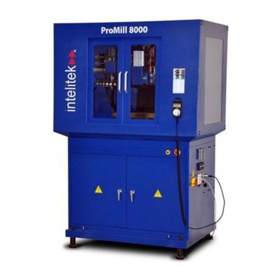
2. Introducing the ProMill 8000 The ProMill 8000 is a versatile PC-based CNC milling center that enables you to deliver robust instruction in computer numerical control and advanced manufacturing. The ProMill 8000 comes equipped with 3-axis stepper motors, ball screws, a variable speed A/C powered brushless spindle motor, limit/home switches, and an ISO 20 taper spindle with a 10 mm maximum tool diameter and 150 mm throat. - Page 14 Safety door and limit switches Emergency stops from the milling center and computer keyboard Machine ready optional accessories Coolant ready Jog pendant ready Robotic integration ready with 6 inputs, 6 outputs 2 Introducing the ProMill 8000 2 .1 Overview of Standard Features...
-
Page 15: Promill 8000 Components
2.2. PROMILL 8000 COMPONENTS This section shows the location of major components of the ProMill 8000, arranged by the view from which they are visible: Section Contents: Components 2 .2.1 External View, pg. 9 2 .2.2 Right Side Panel, pg. 10 ... - Page 16 It is important that this button be pushed in (i.e. engaged) before performing any manual operation, such as changing the stock or tooling. 2 Introducing the ProMill 8000 2 .2 ProMill 8000 Components...
- Page 17 The graphic below shows the machine as viewed from the right side. 1. I/O ports 2. PC power supply 3. Coolant power supply 4. Jog pendant port 5. Ethernet port 6. FANUC panel port 7. On/off switch 2 Introducing the ProMill 8000 2 .2 ProMill 8000 Components...
- Page 18 The graphic below shows the contents exposed by opening the safety shield. 1. Work light 2. Tool release button 3. Spindle Head 4. Automatic tool changer (optional) 5. Lubricant reservoir 6. Cross-slide 2 Introducing the ProMill 8000 2 .2 ProMill 8000 Components...
-
Page 19: Overview Of Cncbase/Motion Control Software
Systems, pg. 39. 2.3. OVERVIEW OF CNCBASE/MOTION CONTROL SOFTWARE The heart of the ProMill 8000 milling center is the control software (CNCMotion or CNCBase) that runs on your computer. Using industry standard EIA RS- 274D NC codes, the control software provides for two-axis CNC programming and milling. -
Page 20: Optional Accessories
2.5. OPTIONAL ACCESSORIES Intelitek offers a variety of milling center accessories, CAM software, curriculum, and documentation. For more information about these products call your Intelitek dealer, call Intelitek directly at (800)221- 2763 or (603) 413-2600, or browse our web site www.intelitek.com. -
Page 21: Installing The Hardware And Software
3. Installing the Hardware and Software This section presents instructions for installing the hardware and software components. Procedure Outline: Installation Step Section Page 3 .1 Prepare your hardware for installation. 3 .2 Install the hardware. 3 .3 Install and configure the software. - Page 22 3. Remove the top of the crate. 4. Remove the sides of the crate. Intelitek is not responsible for any damage caused during shipping when components are not returned in the original packing materials. Store the packing materials at least until the installation is complete and proper operation has been verified.
- Page 23 2. Check that all items on the packing slip are present. See the checklist below. 3. Contact Intelitek Customer Support immediately if any item is missing. Use this checklist to ensure that all items listed on the packing slip are present in the delivery.
- Page 24 2. Locate the registration card within that box. 3. Complete the card, printing all information clearly. 4. Return the card to Intelitek Customer Support at the address below, 3 Installing the Hardware and Software 3 .1 Preparing for Installation...
-
Page 25: Installing The Hardware
Intelitek Customer Support 18 Tsienneto Road Derry, NH 03039 or fax to 603-625-2137 3.2. INSTALLING THE HARDWARE This section presents instructions for installing the ProMill 8000 hardware. Procedure Outline: Hardware Installation Step Section Page 3 .2.1 Connect the milling center to a computer. - Page 26 3.2.3. ProMill 8000 Installing Accessories Each accessory kit is supplied with an installation guide. To avoid stressing the milling center and creating a hazardous milling environment, use only those accessories designed for use with the ProMill milling center, available through Intelitek Corporation. Safety ...
-
Page 27: Installing The Software
Complete the hardware and software installation procedures (see 3 .3 Installing the Software below), and test the functioning of the basic machine, before installing accessories. Product Care 3.3. INSTALLING THE SOFTWARE This section presents instructions for installing the control software (CNCMotion or CNCBase) on the computer. - Page 28 3.3.2. Running the Installation Follow the procedure below to run the installation. Procedure: Running the Installation 1. Insert the installation disk into the CD/DVD drive. The installation program should open automatically. If the installation does not open automatically, navigate to the Install folder and launch the program iCNC.exe.
- Page 29 4. Click Yes to accept and continue. The Software Selection screen is displayed. 5. Select the software to install. It is important that the software you select here matches the license you have purchased. 6. Click Next. The Machine Selection screen is displayed. ...
- Page 30 7. Select the machine you will be using. It is important that the machine selected matches the license you have purchased. 8. Click Next. The Configuration Options screen is displayed. 9. Select whether the configuration and sample programs are to be exclusive to each user (first option) or common to all users (second option).
- Page 31 11. If necessary, click Browse to change the destination folder. 12. Click Next. The Ready to Install screen is displayed. 13. Click Install. 3 Installing the Hardware and Software 3 .3 Installing the Software...
- Page 32 14. Wait while installation is performed. The InstallShield Wizard Complete screen is displayed. 15. Select Yes, I want to restart my computer now. 16. Click Finish. Your computer will restart and installation will be finalized. 3.3.3. Licensing the Software For details on licensing your software and managing or transferring your license, refer to the Licensing Help document that can be found in the Books folder of the software installation disk.
- Page 33 1. Ensure that CNCBase/Motion is not currently running. 2. Click the Windows Start button. 3. Click All Programs. 4. Locate and click the CNCBase/Motion for Intelitek CNC & Fanuc emulator folder. 5. Click CNCBase/Motion Configuration. The CNC Configuration window displays.
- Page 34 3.3.4.2. Using the Configuration Program The table below summarizes the use of the configuration program. Procedures: Using the Configuration Program Instructions View all available settings Click the tabs at the top of the window. Access online help Click the Help button. Save changes made Click OK.
- Page 35 3.3.4.3. Adding Installed Optional Accessories Optional accessories are available for the ProMill 8000 (see 2 .5 Optional Accessories, pg. 13). After installing the accessory hardware, the control software must be reconfigured. Detailed instructions are provided in the installation guide supplied with each accessory. General instructions are provided below.
- Page 36 Follow the procedure below to configure the control software for a new accessory. Procedure: Configuring Control Software for New Accessory 1. Run the configuration program. (See 3 .3.4.1 Running the Configuration Program, pg. 26.) 2. Click the Options tab. 3.
- Page 37 Follow the procedure below to configure the IP address. Procedure: Configuring the IP Address 1. Run the Machine IP Configuration utility. To do so, locate the CNCBase/Motion for Intelitek CNC & Fanuc emulator folder and click Machine IP Configuration. 2. Click Yes if asked for permission.
- Page 38 Procedure: Uninstalling the Software 1. Click the Windows Start button. 2. Click All Programs. 3. Locate and click the CNCBase/Motion for Intelitek CNC & Fanuc emulator folder. 4. Click Uninstall. 3 Installing the Hardware and Software 3 .3 Installing the Software...
- Page 39 5. Click Yes if the User Account Control message displays. The Uninstall Wizard is displayed, asking for confirmation. 6. Click Yes to uninstall CNCBase/Motion. 7. Wait while the software is uninstalled. The Uninstall Complete window is displayed. 8. Select Yes, I want to restart my computer now. 9.
-
Page 40: Contacting Technical Support
3.4. CONTACTING TECHNICAL SUPPORT Should you require technical assistance, contact your local Intelitek dealer. If you are unable to resolve your problem through your local dealer, free technical support is available by phone or email from 8:15 A.M. to 5:00 P.M. EST. - Page 41 4. Write the RMA number and your return address on the outside of the product carton or crate. Failure to do so can result in a delay in the return of your product. 5. Have the package returned to Intelitek’s offices, as directed by the Technical Support representative. 3 Installing the Hardware and Software...
-
Page 42: Maintaining The Promill 8000
4. Maintaining the ProMill 8000 Preventative maintenance of the ProMill 8000 is essential for ensuring a long and trouble- free service life. Product Care This section presents instructions for maintaining the milling center and computer. Maintaining the Milling Center Description... -
Page 43: Maintaining Individual Milling Machine Components
4.2.1. Maintaining the Milling Machine Bed The milling machine bed, saddle, and ball screw all require constant lubrication to prevent wear and rust. The ProMill 8000 is supplied with a one-shot system that simplifies lubrication of these components. Use 15 weight way oil only. - Page 44 Contact your Intelitek customer service group for maintenance or service instructions. 4.2.3. Maintaining the Ball Screw The ProMill 8000 Milling Center uses pre-loaded ball screws on both axes. The screws are lubricated at the factory with a special long-life, waterproof ball screw lubricant. Additionally, the ball screw is lubricated via the one-shot lubrication system.
-
Page 45: Maintenance Schedule Summary
The spindle motor belt will wear out quickly if it becomes loose. If a belt squeals at slow speeds, it may be loose or worn. The spindle drive belt is inside the spindle head. Call Intelitek Customer Service if the belt makes a squealing sound. Product Care 4.3. MAINTENANCE SCHEDULE SUMMARY Follow the maintenance schedule outlined in the table below. -
Page 46: Adjusting And Maintaining The Pneumatic Systems
Section Contents: Adjusting and Maintaining Pneumatic Systems Section Name Page 4 .4.1 Adjusting the Flow Controls 4 .4.2 Adjusting the Air Pressure 4 .4.3 Maintaining the Pneumatic Oil 4 Maintaining the ProMill 8000 4 .4 Adjusting and Maintaining the Pneumatic Systems... - Page 47 The oil flow rate is factory-adjusted and does not require maintenance. The oil level in the oil chamber (see picture above) should be checked regularly and filled when empty. Use standard pneumatic tool oil only. 4 Maintaining the ProMill 8000 4 .4 Adjusting and Maintaining the Pneumatic Systems...
-
Page 48: Maintaining The Pc In A Shop Environment
A line-surge suppression unit can be purchased at your local computer store to help alleviate this problem. Don’t block the vent holes in the computer or drives; they are required for air circulation. 4 Maintaining the ProMill 8000 4 .5 Maintaining the PC in a Shop Environment... -
Page 49: Using The Control Software
5. Using the Control Software The control software, CNCBase or CNCMotion, is used to control all aspects of machine function, to edit and run NC programs, and to verify those programs in simulation mode. CNCMotion additionally provides 3D simulation of the milling procedure. For installation and configuration instructions, see ... - Page 50 4. Locate and click the CNCBase/Motion for Intelitek CNC folder. 5. Click CNCBase/Motion for Intelitek CNC 6. Click No if the message below displays. This message is only displayed the first time the software is run after installation. The software opens.
-
Page 51: Selecting Online Or Simulation Mode
Safety Simulation mode For use without the ProMill 8000 connected. In simulation mode, you can write, edit, and verify NC programs as in on-line mode, but you cannot control or send NC programs to the ProMill 8000. Follow this procedure to toggle between on-line and simulation mode. -
Page 52: Software Interface
5.3. SOFTWARE INTERFACE You should become familiar with the main parts of the control software screen prior to use. This section provides information on the following screen areas: Section Contents: The Software Interface Section Name Page 5 .3.1 Toolbars ... - Page 53 Save Saves the program in the currently active Program Editing window, using its current name. Save as Saves the program in the currently active Program Editing window, under a new name that you specify. Print Prints the NC program in the currently active Program Editing window.
- Page 54 Absolute Position Open or close the Absolute Position Window. See 5 .3.2.2 Actual Position Panel, pg. 54. Machine Info Open or close the Machine Info panel. See 5 .3.2.3 Machine Info Panel, pg. 55. Jog Control Open or close the Jog Control Panel. See ...
- Page 55 Jog Settings Establish speed and distance parameters for jogging the tool. See 5 .3.4.1 The Jog Control Panel, 58. Run Settings Establish options for running an NC part program. See 5 .7 Running an NC Program, pg. 71. Verify Settings Establish options for verifying an NC part program.
- Page 56 5.3.1.2. Standard Toolbar The Standard Toolbar provides easy access to the most often used commands available in the software. The Standard Toolbar includes the buttons below: When using CNCMotion, the following additional buttons are present: Info Table: Standard Toolbar Icon Name Function Opens a new NC part program file.
- Page 57 Saves the current viewing angle and position of the 3D window. The next Save Camera time you open CNCBase/Motion, that saved view will be restored Position automatically. Send Tool to Moves the tool to the workpiece origin immediately. (Available in Simulation Origin mode only.) Send Tool to...
- Page 58 Configure Opens the Configure ATC window. In this window you specify which tool is positioned in each of the tool ATC locations. The tools must first be defined using the Setup Tool Library window. Select a tool station from the Tool Station Use drop-down list. Select the tool that is positioned in that station from the Tool in This Station drop-down list.
- Page 59 The Outputs toolbar is an active toolbar. It provides switches to supply power to the spindle, change spindle direction, power for the accessory outputs, and to the coolant outlet on the right side of the ProMill 8000. Switches for Robotic outputs 1 through 4 are also provided. Power is ON when the buttons are depressed.
- Page 60 5.3.1.5. lnputs Toolbar The Inputs Toolbar is an inactive toolbar. It provides information only on the state of the Emergency Stop, the doors, the automatic safety shield (optional), and the limit switches. Indicators for robotic inputs 1, 2, 3, and 4 are also provided. An input is active (on) when the button is depressed. Info Table: Inputs Toolbar Icon Name...
- Page 61 5.3.2.1. Status Bar The Status bar provides status information on the NC program in progress, the software, and the computer. Info Table: Status Bar Left Side Provides information about the currently selected function. Shows the current feed rate. Shows the current spindle speed. Shows spindle load.
- Page 62 Info Table: Absolute Position Panel Column Displays Absolute The position of the tool in the current coordinate system. Relative The position of the tool relative to the Work coordinates. Machine The position of the tool relative to the machine's home position. Dist to go The distance remaining until the end of the current line of code (if a program or NC code is currently running).
- Page 63 Current work coordinates. Shows the program line number currently being executed, and the total number of program lines. Counts how many parts have been made. 5.3.3. Program Editing Window Whenever you open an NC part program file, it is displayed in its own Edit window. You can have multiple Edit windows open at a time.
- Page 64 Follow this procedure to unlock an NC program for editing. Procedure: Unlocking an NC Program for Editing 1. Click Edit | Lock in the Main Menu to remove the lock. Alternatively, press Ctrl-L on your keyboard. The Edit window’s background color changes to white. Editing is now enabled. ...
- Page 65 5.3.4. Control Panels The ProMill 8000 does not have any controls on the machine itself, other than the Emergency Stop and door release buttons. All control operations are performed from the control software. There are two control panels: The Jog Control panel allows you to move the tool in the X, Y and Z directions, and to control the speed and distance of that motion.
- Page 66 The controls on the Jog Panel are explained below. Info Table: Jog Control Panel Pressing the X, Y and Z buttons moves the tool in the X, Y and Z directions, positively or negatively. You can also use the arrow buttons on your keyboard, when the button is active.
- Page 67 5.3.4.2. The Operator Panel The Operator panel allows you to run programs, control how programs run, and control the feed rate and spindle speed overrides. The controls on the Operator Panel are explained below. Info Table: Operator Panel Runs the program, and recommences program after a pause. Halts the currently running NC part program.
-
Page 68: Homing
Single Step Causes the NC program to pause after each block is executed. This allows you to check each step of the cutting operation. 5.4. HOMING The machine’s Home position is a predefined position. The milling center uses this point as a reference for all machine coordinate movements. -
Page 69: Opening An Nc File
The Machine Home / Reference Point window is displayed. 2. Click: Home to send the machine to the home position at regular speed (recommended). Quick Home to send the tool to the home position at a rapid speed. Use this option only if you are sure that doing so is safe. - Page 70 3. Select the program and click Open. The NC program is displayed. 5 Using the Control Software 5 .5 Opening an NC File...
-
Page 71: Verifying An Nc Program
5.6. VERIFYING AN NC PROGRAM Tool path verification allows you to check for programming errors before actually running the part program on the milling center. The Verify Window displays a 2D simulation of your part program. This section presents the following information: Section Contents: Verify Window Section Name... -
Page 72: Launching Verification
5.6.1. Launching Verification Follow this procedure to launch verification. Procedure: Launching Verification 1. Either click the Verify icon on the Standard Toolbar, or click Program | Verify on the Main Menu, or press F6 on your keyboard. . The Verify Program window is displayed. ... - Page 73 2. Click: Verify Program to commence verification in the Verify window. Run Settings to open the Run Settings window. The settings here specify how the program will run. See 5 .6.2 Modifying Run Settings, pg. 67. Verify Settings to open the Verify Settings window.
-
Page 74: Modifying Run Settings
5.6.2. Modifying Run Settings The settings in the Run Settings window specify how the program will run. The Run Settings window is accessed by clicking Run Settings on the Verify Program window. The settings available in this window are described below. Info Table: Run Settings Window Single Step Allows you to run the program one line at a time, pausing after each line is executed. -
Page 75: Configuring Verify Settings
5.6.3. Configuring Verify Settings The settings in the Verify Settings window specify how the verification is displayed The Verify Settings window is accessed by clicking Verify Settings on the Verify Program window. The Verify Settings window consists of three tabs. The settings available in this window are described below, arranged by tab. - Page 76 Use the Zoom controls to magnify (+), zoom out (-), or view the entire workpiece (All). All changes are reflected in the Preview window. Stock Tab Specifies the length, width, and height of the stock to be used. Spacer specifies the height of the spacer placed beneath the workpiece. Sets the stock origin relative to the front left corner of the stock.
-
Page 77: Using The Verify Window Controls
Specifies the coordinates from which the tool must start motion. 5.6.4. Using the Verify Window Controls The buttons on the toolbar inside the Verify window provide quick access to the display settings. Info Table: Verify Window Controls Displays the workpiece in solid view. Displays the workpiece in wireframe view. -
Page 78: Running An Nc Program
5.7. RUNNING AN NC PROGRAM This section provides instructions on how to run an NC program. Before running the program: 1. Close the safety door. 2. Wear safety glasses. Safety 3. Review all other safety precautions in 1 Safety Guidelines, pg. 1. 4. -
Page 79: Accessing Help
3. Ensure that Start at Line is set to line 1. 4. Click: Run Program to begin running your program. Run Settings to open the Run Settings window. The settings here specify how the program will run. See 5 .6.2 Modifying Run Settings, pg. 67. 5. -
Page 80: Installing A Tool
6. Installing a Tool The ProMill 8000 comes equipped with a pneumatic drawbar which allows for quick and accurate manual tool changes. An automatic tool changer (ATC) is available as an optional accessory. This section provides instructions for manually changing a tool. Instructions for setting up tools in a tool changer are provided in the documentation supplied with that product. -
Page 81: Removing The Tool Holder From The Spindle
6.1. REMOVING THE TOOL HOLDER FROM THE SPINDLE Follow this procedure to remove the tool holder from the spindle. Procedure: Removing the Tool Holder from the Spindle 1. Ensure that the CNC machine is connected to the computer, and that CNCBase or CNCMotion is running on the computer. -
Page 82: Inserting The Tool Holder Into The Spindle
4. Tighten using the tool holder nut wrench. 5. Further tighten the assembly using the appropriate crescent wrench and the tool holder nut wrench. 6.3. INSERTING THE TOOL HOLDER INTO THE SPINDLE Follow this procedure to insert the tool holder into the spindle. Procedure: Inserting the Tool Holder into the Spindle 1. - Page 83 5. Ensure that the tool is installed correctly by holding the tool by the flange of the tool holder and turning the tool and spindle. Ensure that the tool and spindle spin together as one unit. 6 Installing a Tool ...
-
Page 84: Tutorial: Milling A Sample Part
7. Tutorial: Milling a Sample Part This section provides detailed instructions for milling a simple sample part, covering the entire process from NC program verification through milling a complete part on the ProMill 8000. The tutorial will follow this procedure. -
Page 85: Reviewing Safety Procedures
7.1. REVIEWING SAFETY PROCEDURES Like any other power tool, the ProMill Milling Center is a potentially dangerous machine if operated in a careless manner. The importance of safely operating the ProMill Milling Center, including the need for protection against personal injury and the prevention of damage to the equipment, cannot be stressed enough. -
Page 86: Determining The Stock Size
3. Select SUPERMAN_IMP and click Open. The NC program is displayed. The grey background indicates that the program is currently locked for editing. 7.4. DETERMINING THE STOCK SIZE For the Verify window to accurately simulate the NC program, you will have to specify the stock size before running the verification. -
Page 87: Configuring The Verify Settings
In this case, the required dimensions are displayed within the NC program, as shown below. 7.5. CONFIGURING THE VERIFY SETTINGS Before you run the verification simulation, you must adjust the verification settings so that the verification simulation will accurately simulate the tool-workpiece combination you will be using. This section provides instructions for configuring the Verify Settings. - Page 88 7.5.1. Accessing the Verify Settings Window Follow this procedure to access the Verify Settings window. Procedure: Accessing the Verify Settings Window 1. Check to see if the Verify window, shown below, is currently displayed on the CNCBase/Motion screen. If the Verify window is not displayed, click View, and click Verify Window to open it. 2.
- Page 89 The Verify Settings window is displayed. 7.5.2. Adjusting the View Settings Follow this procedure to adjust the view settings. Procedure: Adjusting the View Settings 1. Click the View tab. This tab is used to specify the appearance of the Verify animation. 2.
- Page 90 Follow this procedure to set stock dimensions and origins. Procedure: Setting Stock Dimensions and Origins 1. Select the Stock tab. 2. Enter the stock dimensions for the superman_imp.nc part program. The stock dimensions define the dimensions of the stock outside the chuck. ...
-
Page 91: Defining The Tool
4. Set the initial tool position to: X = 0” Y = 0” Z = 0.5” The settings will ensure that the tool starts 0.5” above the origin corner. 5. Select OK. The window closes and your changes are applied to the workpiece in the Verify Window. 7.6. - Page 92 Procedure: Defining the Tool 1. Click Tools | Setup Library in the Main Menu. The Setup Tool Library window is displayed. 2. Select Tool 01, a 0.125” endmill. 3. Check that the settings for Tool 01 are as shown below. If they are not, modify the settings to match the settings shown.
-
Page 93: Verifying The Program
7. Click Select Tool. 8. Tool 01 is now selected. 7.7. VERIFYING THE PROGRAM Tool path verification allows you to check for programming errors before actually running the part program on the Milling Center. Follow this procedure to verify the program. Procedure: Verifying the Program 1. -
Page 94: Turning On And Homing The Machine
The program is verified. Upon completion the Normal Program Stop window is displayed. 4. Click OK. 7.8. TURNING ON AND HOMING THE MACHINE The Verify procedure you have just completed verified that the path the tool is to follow will almost certainly not result in any collisions with the workpiece or vise. -
Page 95: Mounting The Workpiece
7.9. MOUNTING THE WORKPIECE Although you will first test the program without a workpiece in place, you must initially mount the workpiece so as to be able to set up the machining axes relative to the workpiece. Follow this procedure to mount the workpiece. Procedure: Mounting the Workpiece 1. - Page 96 3. Using the Jog Control window options, carefully jog the tool down towards the piece of paper on top of the workpiece. Stop when you are about 0.5 inches away from the paper. Note the following: Click the arrow buttons or press the arrows keys on your keyboard to move the tool. b.
- Page 97 d. To adjust the preset Speed and Step Size values: i. Right-click anywhere in the Jog Control panel. A menu is displayed. ii. Click Setup. The Jog Settings window is displayed. iii. Change the settings as required and click OK. ...
- Page 98 4. When you are about half an inch away from the paper, switch to the slowest speed and 0.01 inch step size and jog the tool closer to the paper. Stop when you are just above the paper. 5. When you are just above the paper, switch to 0.001 inch steps. Carefully jog the tool down until the tool tip just pinches the paper.
- Page 99 Jog the tool up, away from the surface of the workpiece. When you are a small distance away from the workpiece, switch to continuous movements and move the tool about 1 inch above the workpiece. 11. Hold the piece of paper against the front of the workpiece. 12.
-
Page 100: Performing A Dry Run
7.11. PERFORMING A DRY RUN You will now perform a dry run. In other words, you will run the program on the machine without a workpiece in place. The Emergency button must be pressed in before starting this procedure. Safety Follow this procedure to perform a dry run. -
Page 101: Running The Program
7. Click the Run Program button. The machine begins running the program. Be prepared to press the Emergency Stop button on the milling center, if it looks like a collision may occur. Safety As the part program runs, observe the tool motion in relation to the vise, other fixtures in the machine, and the future location of the workpiece. - Page 102 3. Click Program | Run/Continue in the Main Menu. The Run Program window is displayed. 4. Ensure that Start at Line is set to line 1. 5. Click Run Program to begin running your program. 6. Once the program has ended, press the Emergency button, open the safety door, and remove the finished part.
-
Page 103: Basic Cnc Programming
8. Basic CNC Programming This section provides a basic reference for basic CNC programming. This section presents the following information. Section Contents: Basic CNC Programming Section Name Page 8 .1 Elements of an NC Part Program 8 .2 General Programming Suggestions ... -
Page 104: General Programming Suggestions
This is the block sequence number for the program. Block 1 is the first block in the program. Indicates absolute coordinates are used to define tool position. Specifies linear interpolation. Specifies the X axis destination position as 0.5". Specifies the Y axis destination position as 0.5". Z1.5 Specifies the Z axis destination position as 1.5". -
Page 105: Reviewing An Nc Program
Last movement command in The last block of a program should move the tool back to the starting program position. The tool will then be in position to start cutting another part. 8.3. REVIEWING AN NC PROGRAM Once an NC program has been written, it must be checked carefully before the first part is machined. Errors in an NC program can cause machine damage and injury to the operator. - Page 106 8 .4.11 Loop counter Program cycle (repeat) Single counter for blocks and sub- programs, angle of arc resolution 8 .4.12 Miscellaneous codes Multiple 8 .4.13 Block number (user reference only) Single 8 .4.14 Subprogram starting block number Single ...
- Page 107 In the EIA-274 mode, arc centers are based on the selected coordinate mode: absolute (G90) or incremental (G91). In contrast, arc center specifications in Fanuc mode (specified by the % code) are always incremental, regardless of whether the system is set to absolute or incremental coordinate mode.
- Page 108 The various G codes are divided into different groups. Multiple G codes from different groups can appear in each NC block. However, you may not place more than one G code from a group in one block. The ProMill 8000 supports the following G code groups. Info Table: G Code Groups...
- Page 109 Circular interpolation (counterclockwise) 8.4.6.2. The Units Group By default, an NC program is interpreted using the units of measure (inch or metric) specified using the Units command on the Setup menu. The codes in the Units Group, G70 (inch) and G71 (metric), are used to override the Units setting for the entire program.
- Page 110 Pause Used for operator intervention. Stop motion on all axes until the operator manually resumes program execution using the Run/Continue command or the Run button Wait until input goes high before executing the operations in this block. Used for robot synchronization (see 1 2 Automation lntegration, pg. 166). Example: G25H13;...
- Page 111 9 .6.4 Thread tapping 9 .6.5 Boring cycle 9 .6.6 Straight drilling with spindle stop 9 .6.7 Boring with dwell 8.4.6.5. The Programming Mode Group Programming Mode G codes select the programming mode, absolute (G90) or incremental (G91). These codes remain in effect until superseded by each other.
- Page 112 8.4.6.6.1. G28 and G29: Homing Commands The Homing feature in the control software sends the machine to the predefined Home position (0,0,0). This is used as a reference for other motion. The homing commands (G28, G29) allow you to return to and check this established position. The milling center uses this point as a reference for all machine coordinate movements.
- Page 113 Multiple coordinate systems can be useful for different size workpieces, or for special set-up conditions. There are seven coordinate system codes. One of these codes (G53) is used for rapid traverse motion to specified machine coordinates. The other six codes allow you to make up to six individual parts on the same workpiece by specifying different work coordinate systems for each part.
- Page 114 G91 X1.5 Y1 X.75Y0 M98 P1 L12 O1 Y30 G81 Z-.1 R0 Code Explanation G0X0Z0.07M03 Rapid motion to X0Z0.07. Spindle ON. G16 G91X2Z0 M98P1L12 Turn Polar programming ON. Incremental programming mode ON. X2Z0 Move to a point 2 inches from the current position, at an angle of 0 degrees.
- Page 115 A second example is shown below. NC Code Example: G0 X0Y0Z0 G91X2Z0 Z-.1 M98P1L90 O1Y1 Code Explanation Turn Polar programming ON. G91X2Z0 Incremental programming mode ON. Z-.1 Move to a point 2 inches from the current position, at an angle X2Z0 M98P1L90 of 0 degrees.
- Page 116 The supported compensation codes are listed in this table. Info Table: Compensation Functions Group Code Function Section Page 8 .4.6.9.1 Corner offset circular interpolation 8 .4.6.9.2 Cancel cutter compensation 8 .4.6.9.3 Left cutter compensation Right cutter compensation ...
- Page 117 8.4.6.9.2. G40: Cancel Cutter Compensation Use the G40 Cancel cutter compensation code to cancel cutter compensation. G40 is effective for only one move. There are six methods for cancelling cutter compensation, described in the table below. Info Table: Cancelling Cutter Compensation Method Explanation Example...
- Page 118 G91G41D1 Setting the offset number to zero cancels … cutter compensation. The cutter moves X.25 from the offset path to the programmed end point. Y-.25 Setting the offset number to zero has Z.2; RETRACT the same effect as cancelling cutter compensation (see 1).
- Page 119 8.4.6.9.3. G41 and G42: Left and Right Cutter Compensation The G41 and G42 codes command left and right cutter compensation as illustrated below. Info Table: Left and Right Cutter Compensation Code Explanation Explanation Left compensation when you need to move the tool to the left of the programmed tool path.
- Page 120 In the example below, left cutter compensation is enabled and the compensation value is equal to offset value 1 from the Offset Table. NC Code Example: G0X0Y0 G91; INCREMENTAL G41D1; CUTTER COMP ON G1X.25Y.25; MOVE TO P1 G1X0Y1; MOVE TO P2 G1X.75Y0;...
- Page 121 Note that an NC program will use the offset values as listed in this window, without converting for metric or imperial systems. The Units selection area in the window converts the values in this window. 8.4.6.10. Scaling Group Use the Scaling codes to scale one or more axes of a part from a fixed scaling origin. You can scale the entire piece uniformly, or set different scaling factors for each axis.
- Page 122 Example Code: Scaling Code Explanation G51X0Y0Z0I2J2K1 Initiates scaling. Sets the origin of scaling to X0Y0Z0. X0Y0Z0 I2J2K1 Scales X and Y axes by 2, and the Z axis by 1. 8.4.6.11. Rotation Group Rotation codes allow you to rotate a programmed shape around a rotation origin. You can rotate a shape on any plane, one plane at a time.
- Page 123 Info Table: Selecting a Plane for Circular Interpolation Code Selects Arc Center Coordinates Plane Specification I for the X axis, J for the Y axis I for the X axis, K for the Z axis J for the Y axis, K for the Z axis 8.4.7.
- Page 124 Absolute The X coordinate of the arc/circle center, measured from the origin. Note: In Fanuc mode, all arc centers are specified in incremental mode. Incremental The distance along the X direction from the starting point of motion to the arc/circle center. The I code is also used with the G51 code to specify the scale factor for the X axis when performing scaling functions, including scaling each axis and mirror scaling.
- Page 125 8.4.11. L Code: Angle of Arc Resolution, Loop Counter The L code is used in three unrelated ways, as listed below. Section Contents: Angle of Arc Resolution, Loop Counter Description Section Page 8 .4.11.1 L Code: Angle of Arc Resolution To specify the resolution of an arc or circle ...
- Page 126 Calculating L If you know the chord length you would like used when approximating an arc or circle, calculate the angle L as follows: Calculation: Calculating the Value of L Calculation Where: 360 ∙ �� c is the desired chord length. ��...
- Page 127 8.4.11.2. L Code: Loop and Program Counter The L code functions as a counter when used with codes M98 and M47: Info Table: L Code Used as a Counter When Used L Specifies Section Page With 8 .4.12 M Codes: The number of times a program must be repeated.
- Page 128 Spindle and Spindle Motor On Axis Motor Activated concurrently with motion specified in the program block; remains in effect Group until superseded by M05. Spindle Motor Off Activated after the motion specified in the program block; remains in effect until superseded by M03.
- Page 129 See 8 .4.12.2 M99 Code: Return from SubProgram, Goto, pg. 124, and 9 .7 Subprogram Programming, pg. 143. M105 Operator Message A nonstandard Intelitek code used to display messages. See 8 .4.12.3 M105 Code: Operator Message, pg. 124. Homing Group M111 Home the X axis.
- Page 130 Enter standard text to be written in each line. Text can be written in front of, between, or text after macros. If no text or macros are specified, the actual machine position data will be written. Codes such as @TD (time of day) and @ (cycle number) can be specified to include a special codes range of data.
- Page 131 ; Output part time statistics to file c:\Reports\Stats.txt (c:\Reports directory must exist) M22 (c:\Reports\Stats.txt,A) Part #@C processed in @TC. M47 L50 ; We want to process 50 parts. 8.4.12.2. M99 Code: Return from SubProgram, Goto The M99 code has two specific uses; it can be used as a command to return from a subprogram or it can be used as a Goto command.
- Page 132 Info Table: Special Codes for Use With M105 Code Function Displays the message and performs a pause requiring operator intervention to continue. Displays the message as a Warning Message. Beeps when the message is shown. The M105 code is used with special codes as in the format below: M105 (alternate character plus the message) ;comment For example: Example Code: Use of M105 with Special Codes...
- Page 133 Example Code: Use of O Code M98 P50000 ;call to first subprogram …;after first subprogram is finished, M99 code returns to this point … M98 P60000 ;call to second subprogram …;after second subprogram is finished, M99 code returns to this point …...
- Page 134 For example, T3 is the designation for tool number three. Using multiple tools is an advanced operation and should not be attempted by persons unfamiliar with using the ProMill 8000 milling center. Safety See 1 0 Multiple Tool Programming, pg. 145.
- Page 135 Below is an example of an NC block with a comment: Example Code: Comment Code Explanation X0Z0; MOVE TO ZERO POINT The comment in the example tells us that the X and Z codes in this block command the cutting tool to move to the zero point (coordinate 0,0). Comments can be combined with the G05 pause and the M06 tool change codes to display messages to the operator during program execution.
-
Page 136: Nc Programming Routines
9. NC Programming Routines This chapter describes the use of the following NC programming routines: Section Contents: NC Programming Routines Section Name Page 9 .1 Linear Interpolation Programming 9 .2 Circular Interpolation Programming 9 .3 Circular Interpolation Programming in Other Planes ... -
Page 137: Circular Interpolation Programming In The Xy Plane
Example If we assume that the current position of the tool is X.7, Y2, Z1.2, the tool movement Motion generated by the example code will be as follows. (Only X and Z axes are shown.) Equivalent An equivalent movement is achieved with incremental dimensioning (G91): Code N5G91G01X.3Y0Z-.7F2 9.2. - Page 138 The codes used in circular interpolation are listed below. Info Table: Circular Interpolation Codes Code Explanation Moves tool along circular path in clockwise direction. Moves tool along circular path in counterclockwise direction. Specifies X-axis coordinate of center point Specifies Y-axis coordinate of center point An example of circular interpolation is shown below.
-
Page 139: Circular Interpolation Programming In Other Planes
The second line defines the end point and the center point. N10G02X1Z-.10I.5J0F2; CLOCKWISE TO X1,Y0,Z-.1 The line sequence number is 10 The tool will proceed in a clockwise direction from the starting point to specified (X, Z) coordinates; center point of arc is specified by (I,K) coordinates X axis coordinate of end point to increase by 1 to X1 Z-.10... -
Page 140: Rapid Traverse Programming
J for the Y axis, K for the Z axis An example of circular interpolation in the XZ plane is shown below. NC Code Example: N9X0Z0 N10G90G18G03X0Z1I0K.5F2 Code Explanation N9X0Z0 Sets initial position to X0Z0. N10G90G18G03X0Z1I0K.5F2 The line sequence number is 10 Indicates absolute coordinates are used to define tool position. -
Page 141: Helical Interpolation Programming
NC Code Example: G90G01X1F2; MOVE IN A STRAIGHT LINE TO X = 1 AT 2 IPM G00X2; RAPID TRAVERSE TO X=2 X3; RAPID TRAVERSE TO X=3 G01X4; MOVE IN A STRAIGHT LINE TO X=4 AT 2 IPM Code Explanation G90G01X1F2; MOVE IN A Sets absolute coordinates STRAIGHT LINE TO X = 1 AT 2 IPM... -
Page 142: Canned Cycle Programming
They are typically used for repetitive operations to reduce the amount of data required in an NC program. Canned cycle codes are retained until superseded in the program by another canned cycle code. The table below lists all canned cycles supported by the ProMill 8000 and its control software. Info Table: Supported Canned Cycles Code... - Page 143 9 .6.6 Straight drilling with spindle stop 9 .6.7 Boring with dwell The G80 command is used to cancel all of the canned cycles: Info Table: Additional Canned Cycle Codes Code Explanation Section Page 9 .6.1 Canned cycle cancel The following codes are used within canned cycle codes.
- Page 144 A typical use of the G81 and G83 codes is shown in the following example. NC Code Example: G0X1Y1Z1;RAPID TO INITIAL POINT (1,1,1) G98G81Z-.1R.1F2;CENTER DRILL TO DEPTH OF Z-.1 FROM Z.1 FEED 2, RAPID TO INITIAL POINTG99G83Z-.5R0Q.1F3;PECK DRILL TO Z-.5 FROM Z0 EACH PECK .1, RAPID TO POINT R0 G80;CANCEL CANNED CYCLE M2;END PROGRAM...
- Page 145 Example Motion The straight drill cycle will result in motion as shown below. The peck drill cycle will result in motion as shown below. 9.6.3. G82: Straight Drilling with Dwell A G82 code works just like a G81 code (see 9 .6.2 G81 & G83: Straight and Peck Drilling, pg. 136), except that it allows for a dwell (P code) at the bottom of the hole (point Z).
- Page 146 G0X1Y1Z.1; RAPID TO 1,1,.1 G82G98Z-.5R0P5F2; DRILL TO DEPTH OF -.5, RAPID TO INITIAL POINT AFTER DWELL OF 5 SECONDS. G80; CANCEL CANNED CYCLE M2; END PROGRAM Code Explanation G82G98Z- Straight drill with dwell .5R0P5F2; DRILL TO DEPTH OF -.5, Rapid move to initial tool position after canned RAPID TO INITIAL cycle complete.
- Page 147 The use of the G85 code is shown in following example. NC Code Example: G0X1Y1Z.1; RAPID TO 1, 1, .1 G85G98Z-.5R0F2; BORE TO DEPTH OF -.5, RAPID TO INITIAL POINT FROM POINT R G80; CANCEL CANNED CYCLE M2; END PROGRAM Code Explanation G85G98Z-.5R0F2;...
- Page 148 NC Code Example: G0X1Y1Z.1; RAPID TO 1, 1, .1 G86G98Z-.5R0P5F2; DRILL TO DEPTH OF -.5, SHUT OF SPINDLE, RAPID TO INITIAL POINT AFTER DWELL OF FIVE SECONDS G80; CANCEL CANNED CYCLE M2; END PROGRAM Code Explanation G86G98Z-.5R0P5F2; DRILL TO Straight drilling, stop spindle rotation before DEPTH OF -.5, SHUT OF SPINDLE, retraction.
- Page 149 The use of the G89 code is shown in following example. NC Code Example: G0X1Y1Z.1; RAPID TO 1, 1, .1 G89G98Z-.5R0P5F2; BORE TO DEPTH OF -.5, PAUSE FOR 5 SECONDS, RAPID TO INITIAL POINT FROM POINT R G80; CANCEL CANNED CYCLE M2;...
-
Page 150: Subprogram Programming
9.7. SUBPROGRAM PROGRAMMING Subprograms are used to execute repetitive routines in an NC program. The subprogram is entered in the NC code only once, but can be called and run any number of times. This is especially useful if the milling operation you wish to repeat is lengthy or complex. - Page 151 ;USE 7.25 X 3.00 STOCK TO VERIFY G00 X1 Y1 Z.1 ;RAPID TO 1, 1, .1 M98 P1000 L4 ;RUN SUBPROGRAM 4 TIMES G90 G00 X0 Y0 Z.1 M2 ;END OF MAIN PROGRAM O1000 ;SUBPROGRAM TO MILL SQUARE AND MOVE G90 G01 Z-.1 F2 ;PLUNGE AT CURRENT LOCATION G91 ;INCREMENTAL COORDINATES X1 F5 ;FIRST MOVE, FEED 5...
-
Page 152: Multiple Tool Programming
Using multiple tool programs provides the advanced user with the ability to create more complex parts on the milling center. If fitted with the optional automatic tool changer (ATC), the ProMill 8000 will automatically change tools during program execution. If the ATC is not fitted, the control software will prompt the user to manually change tools as required during program execution. -
Page 153: Specifying The Tools
10.1. SPECIFYING THE TOOLS For the control software to successfully run a multi-tool program, you must specify the tools being used. Follow the procedure below to specify the tools. Procedure: Specifying the Tools 1. Click Tools | Setup Library to access the Setup Tool Library. -
Page 154: Writing An Nc Program For Multiple Tools
Follow the procedure below to configure the ATC. Procedure: Configuring the ATC 1. Click Tools | Configure ATC to access the Configure ATC window. The Tool Station Use area shows which tool is currently present in each of the four tool stations. -
Page 155: Establishing The Reference Tool
The code below demonstrates the use of T and M06 codes for changing tools. Example Code: Tool Change N7 ; Tool #1: 'End Mill' N8 ; Tool #2: 'Ball Mill' N9 G70 ; Inch Units N10 M03 S1500 N11 M06 T01 ; Toolchange to Tool #01 N12 G04 F5 ;... -
Page 156: Setting Tool Offsets
7. Jog the tool slowly until it just touches the reference point. Follow the guidelines below. a. Use Continuous mode (selected in the Step Zone area of the Jog Control panel) to move the tool towards the reference point, but stop motion before the tool is in range of touching the reference point. - Page 157 Follow this procedure to set tool offsets. Procedure: Setting Tool Offsets 1. Establish the reference tool as described in the previous section, 1 0.4 Establishing the Reference Tool, pg. 148. 2. Jog the tool to a safe distance from the workpiece or gauge to prevent a collision when changing the tool. Click Tools | Select Tool 3.
- Page 158 8. Select Tool #02 from the list at the left. 9. Click Use Current Z. The offset value is automatically filled with the position value found in step 6 . 1 0 Multiple Tool Programming 1 0.5 Setting Tool Offsets...
-
Page 159: Testing The Multi-Tool Program
10. Click OK to save the changes and close the window. The offset for Tool #02 is now defined. 11. Repeat this procedure for Tools #03 and #04, if they will be used. 10.6. TESTING THE MULTI-TOOL PROGRAM As for any NC program, a multi-tool NC program must be tested by performing a dry run (running the program without a workpiece in place), before running the program with a workpiece in place. -
Page 160: Tutorial: Running A Multi-Tool Program
TUTORIAL: RUNNING A MULTI-TOOL PROGRAM This section provides detailed instructions for milling a sample part using multiple tools, covering the entire process from NC program verification through to milling a complete part on the ProMill 8000. The tutorial will follow the procedure below. - Page 161 10.7.4. Defining the Tools The sample NC program uses three tools to turn the part. These tools must be defined in the Setup Tool Library. For instructions on defining tools, see 1 0.1 Specifying the Tools, pg. 146. Specify the two tools as detailed in the table below. Tool Specifications Tool 1 Tool 2...
- Page 162 Verify Settings Setting Initial Tool X = 0 Position Y = 0 Z = 0 Stock X = 3.0 Dimensions Y = 2.0 Z = 1.5 Origin X = 0 Y = 0 Z = 0 10.7.7. Verifying the Program Tool path verification allows you to check for programming errors before actually running the part program on the Milling Center.
- Page 163 The Verify window should output a part as shown below. 10.7.8. Establishing the Reference Tool When using multiple tools, a reference tool, normally Tool #01, is set to zero for the Z axis. This establishes a reference tool position which is used as a reference point for additional tools. For instructions on establishing a reference tool, see ...
- Page 164 10.7.10. Testing the Program As for any NC program, a multi-tool NC program must be tested by performing a dry run (running the program without a workpiece in place), before running the program with a workpiece in place. For instructions on performing a dry run, see 1 0.6 Testing the Multi-tool Program, pg. 152. 10.7.11.
-
Page 165: An Introduction To Cnc Milling
11. An Introduction to CNC Milling This section provides a basic introduction to CNC milling. The following topics are covered. Section Contents: An Introduction to CNC Milling Section Name Page 1 1.1 Understanding Coordinate Systems 1 1.2 Setting Spindle Speeds ... - Page 166 11.1.2. Machine Home Position The machine home is a specific and factory-set location to which the tool can be sent through the control software. The machine uses the home position as a reference point for all operations. If the machine is not homed, it cannot accurately locate the workpiece on the cross slide. The machine home location is located as follows: Info Table: Machine Home Position Location Axis...
- Page 167 The user defines the point of origin, and the machine will measure X, Y, and Z coordinates from that point. The machine home position is almost never used as the point of origin, so the coordinates of the home position are seldom (0,0,0). The point of origin can be located anywhere on the workpiece, but is often set to the front, top left corner of the workpiece, as shown below.
-
Page 168: Setting Spindle Speeds
The Setup Coordinate Systems window is displayed. 3. Select one of the G54 to G59 codes 4. Enter the coordinates for the first workpiece, and click on Apply. 5. Repeat this procedure for as many coordinate systems as necessary by setting up a coordinate system for each point on the part that corresponds to the zero point of the shape you are milling. -
Page 169: Setting Feed Rate And Depth Of Cut
Heat High spindle speeds may produce excess heat which can cause the workpiece to expand. If production the workpiece expands, the cutting tool will rub rather than cut the material, resulting in a poor surface finish. Material Some materials require higher spindle speeds to ensure a good finish. type Load on Heavy cuts at low speeds will make the motor run hotter than lighter cuts at higher... -
Page 170: Selecting Lubricants And Coolants
Short runs of parts on Delrin or aluminium, such as would be performed in a school or college laboratory, do not require the use of coolant. The ProMill 8000 milling center is designed for flood cooling. A cooling accessory is available. Contact your dealer or Intelitek. - Page 171 1 1.5.3 Drilling Tools 1 1.5.4 Engraving Tools 1 1.5.5 Roughing and Finishing Tools 11.5.1. End Mills An end mill is a tool with two or more teeth. The most commonly used end mills have two teeth and a flat-tip.
-
Page 172: Sharpening The Tools
11.5.4. Engraving Tools An engraving tool has a single sharp cutting tip. The engraving tool is used to produce very shallow, narrow, and fine cuts into the workpiece face. 11.5.5. Roughing and Finishing Tools Two-tooth tools are generally used for roughing operations. These tools can be moved very quickly to cover a large surface area. -
Page 173: Automation Lntegration
12.1. INTEGRATION INSTRUCTIONS In order to be integrated into an FMS the ProMill 8000 must be able to work with machine related automation functions like an automated shield and an automated clamping device. It must also be able to communicate with a robot for the loading and unloading sequence and be able to run a G Code by command from an external control device, such as a robot program, device driver or other control entity. - Page 174 Shield The automatic shield opener, in closed position The I/ ports located at the right side of the machine Wiring guidelines are presented in the diagram and table below. From Shield Opener To Machine I/O Assembly Panel 24V A 24 V 24V B 24 V OPEN...
- Page 175 The automated clamping device, shown in the photograph below (left), closes and holds the part securely during the machining process. The device opens to allow an automated loading device to load a new workpiece or remove a finished part. The pneumatic pressure regulator system, shown in the photograph below (right), is mounted on the spindle motor access door on the right side of the machine as shown.
-
Page 176: Cnc Programming For Robotic Communication
Most vertical articulated robots on the market can be integrated with Intelitek CNC machines. Specific G Codes, called CHAIN TO FILE and CHAIN to COM G Codes, allow the ProMill 8000 to receive string information. An external control device, such as a robot or device driver, can run any CNC program via this interface. - Page 177 Transmit Low signal Specifies the input or output number. The default is H1. The H code is used in conjunction with the Wait and Transmit codes. Example - G25H3 Input This code tells the CNC machine to wait until the state at input #3 goes High. Assuming the robot’s initial output state is Low, if this line of code is placed at the beginning of the program, the CNC machine waits until input #3 goes High, then executes the next line of code.
-
Page 178: Sample Robot - Cnc Communication Sequence
This sample shows a typical sequence with a robot run by the SCORBASE programming language from Intelitek, with the robot defined as the master and the CNC as the slave. The machine is waiting in standby by running a program that monitors the communication channel (either a RS232 port or a file). - Page 179 Set fs = CreateObject("Scripting.FileSystemObject") TempFileName = FileDirectory + "chain_file.$$$" FileName = FileDirectory + "chain_file.txt" fs.CreateTextFile TempFileName 'Create a file Set f = fs.GetFile(TempFileName) Set ts = f.OpenAsTextStream(ForWriting, TristateUseDefault) ts.Write FileDirectory 'write into the file ts.Write NcProgram 'write into the file ts.Close ' close the file fs.Copyfile TempFileName,FileName fs.deletefile TempFileName...
- Page 180 Call Subroutine PLACE VICE IN LOADING POSITION Remark: ************************************************************************************************ Set Subroutine PLACE VICE IN LOADING POSITION Call Subroutine SCRIPT.PLACE Call Subroutine SYNCHRONIZE_WITH_PM8000 Return from Subroutine Remark: ************************************************************************************************ Step 4 The program name is transferred to the CNC control via the script file and the machine executes the task.
- Page 181 Step 7 The robot monitors the CNC’s input signal. The robot opens the clamping device if the machine signals that it is idle. If Input 1 Off Call Subroutine PM8000 NOT READY Call Subroutine OPEN VICE Remark: ************************************************************************************************ Set Subroutine OPEN VICE Call Subroutine SCRIPT.
- Page 182 M26 H11 ;USER OUT#1 OFF M25 H4;CLOSE VICE G04F1;MAKE SURE OUTPUT IS SEEN M20;CHAIN TO PROGRAM START.NC Step 11 The robot monitors the CNC’s input signal. Once the machine signals that it is idle, the robot exits the machine and closes the door. Open Gripper Go Linear to Position SCRIPT.P2 Speed 30 (%) If Input 1 Off Call Subroutine PM8000 NOT READY...
- Page 183 G0 X0 Y0 Z100 ;***************************************************************** Between these two lines the actual manufacturing code is written ;***************************************************************** G0 X0 Y25 Z20 G0 Z50 M20;CHAIN TO PROGRAM START.NC Step 14 Once the input interrupt that monitors the CNC machine is activated, the robot will start the unloading sequence as soon as the robot is available.
- Page 184 Call Subroutine SYNCHRONIZE_WITH_PM8000 Return from Subroutine Remark: ************************************************************************************************ Step 17 The program name is transferred to the CNC control via the script file and the machine executes the task. ODOOR.NC (Sample) M26 H11 ;USER OUT#1 OFF M25 H102 ;OPEN DOOR G04F2;MAKE SURE OUTPUT IS SEEN G25 H132;...
- Page 185 Step 20 The robot monitors the CNC’s input signal. Once the machine signals that it is idle the robot extracts the part from the VICE and closes the VICE. Go to Position SCRIPT.P2 Speed 50 (%) Go to Position SCRIPT.P3 Speed 50 (%) If Input 1 Off Call Subroutine PM8000 NOT READY Call Subroutine CLOSE VICE Remark: ************************************************************************************************...
-
Page 186: Sample Robotic - Cnc Lntegration Programs
G04F2;MAKE SURE OUTPUT IS SEEN G25 H131; Wait door closed M20;CHAIN TO PROGRAM START.NC Step 24 The robot transfers the part to the next process or to its target storage. 12.4. SAMPLE ROBOTIC - CNC LNTEGRATION PROGRAMS This section presents a selection of sample programs used for integrating a CNC machining center in an FMS. - Page 187 M20;CHAIN TO PROGRAM START.NC CDOOR.NC M26 H11 ;USER OUT#1 OFF M26 H102 ;CLOSE DOOR G04F2;MAKE SURE OUTPUT IS SEEN G25 H131; Wait door closed M20;CHAIN TO PROGRAM START.NC OVICE.NC M26 H11 ;USER OUT#1 OFF M26 H4;CLOSE VICE G04F1;MAKE SURE OUTPUT IS SEEN M20;CHAIN TO PROGRAM START.NC CVICE.NC...
- Page 188 g00 x45 y20 g01 x45 y20 z-2 g01 x45 y27 g01 x45 y27 z2 g00 x52 y35 g01 x52 y35 z-2 g01 x52 y35 z2 g00 x38 y35 g01 x38 y35 z-2 g01 x38 y35 z2 g00 x0 y0 z10 ;***************************************************************** G0 X0 Y25 Z20 G0 Z50...
- Page 189 OPEN VICE DRAW( ---OPEN PM8000 VICE --- ) MSWINDOWS(cscript O:\ project_name \WS3\MILL\CHAIN.VBS OVICE) CLOSE VICE DRAW( ---CLOSE PM8000 CHUCK --- ) MSWINDOWS(cscript O:\ project_name \WS3\MILL\CHAIN.VBS CVICE) PLACE DRAW( ---PLACE PM8000 VICE--- ) MSWINDOWS(cscript O:\ project_name \WS3\MILL\CHAIN.VBS VICE) 12.4.3. Sample SCORBASE Programs Shown below is a sample SCORBASE program for use in a typical FMS station in an OpenCIM/FMS environment.
- Page 190 Set Variable SCRIPT.PICK_AND_PLACE_NOTE = PICK_AND_PLACE_NOTE Return from Subroutine Remark: ************************************************************************************************ Set Subroutine GET001 Print to Screen: GET TEMPLATE FROM CONVEYOR (CNV1) Call Subroutine SCRIPT.GET_FROM_CNV1 Print to Screen: P1,P2,P3,PB1: 'SCRIPT.P1', 'SCRIPT.P2','SCRIPT.P3','SCRIPT.PB1' Go to Position SCRIPT.P3 Fast Go to Position SCRIPT.PB1 Fast Open Gripper Go to Position SCRIPT.P2 Fast Go Linear to Position SCRIPT.P1 Speed 30 (%)
- Page 191 Close Gripper Go Linear to Position SCRIPT.P2 Fast Send Message $Start to MANAGER ID=TASK_ID Return from Subroutine Remark: ************************************************************************************************ Set Subroutine PUT031 Print to Screen: PUT TO BUFFER3 Call Subroutine SCRIPT.PUT_TO_BUFFER3 Print to Screen: P1,P2,P3,PB1: 'SCRIPT.P1', 'SCRIPT.P2','SCRIPT.P3','SCRIPT.PB1' Go to Position SCRIPT.P3 Fast Go to Position SCRIPT.PB1 Fast Go to Position SCRIPT.P2 Fast Go Linear to Position SCRIPT.P1 Speed 30 (%)
- Page 192 Send Message $Start to MANAGER ID=TASK_ID Return from Subroutine Remark: ************************************************************************************************ Set Subroutine PUT032 Print to Screen: PUT_TO_MILL (PM8000) Call Subroutine SCRIPT.PUT_TO_MILL1 Print to Screen: P1,P2,P3,P4,PB1: 'SCRIPT.P1', 'SCRIPT.P2','SCRIPT.P3','SCRIPT.P4','SCRIPT.PB1' Go to Position SCRIPT.P4 Speed 50 (%) Go to Position SCRIPT.PB1 Fast If Input 1 Off Call Subroutine PM8000 NOT READY Call Subroutine PLACE VICE IN LOADING POSITION If Input 1 Off Call Subroutine PM8000 NOT READY...
- Page 193 Go Linear to Position SCRIPT.P3 Speed 50 (%) Go to Position SCRIPT.P4 Speed 50 (%) Send Message $Start to MANAGER ID=TASK_ID Return from Subroutine Remark: **************************************************************************** Set Subroutine PUT033 Print to Screen: PUT TO FEEDER Print to Screen: SHOULD NEVER HAPPEN Return from Subroutine Remark: **************************************************************************** Set Subroutine GET034...
- Page 194 Set Subroutine SYNCHRONIZE_WITH_PM8000 Print to Screen: Synchronizing with PM8000 for Loading/Unloading PM8000_IDLE_OFF: Wait Until Digital Input 1 is OFF Wait 1 (10ths of seconds) PM8000_IDLE_ON: Wait Until Digital Input 1 is ON Wait 1 (10ths of seconds) PM8000_SIGNAL_ON: Return from Subroutine Remark: ************************************************************************************************ Set Subroutine WAIT_CYCLE_END_PM8000 Wait 10 (10ths of seconds)
- Page 195 Call Subroutine SYNCHRONIZE_WITH_PM8000 Return from Subroutine Remark: ************************************************************************************************ Set Subroutine PLACE VICE IN LOADING POSITION Call Subroutine SCRIPT.PLACE Call Subroutine SYNCHRONIZE_WITH_PM8000 Return from Subroutine Remark: ************************************************************************************************ Set Subroutine PM8000 NOT READY Print to Screen & Log: PM8000 NOT READY!!! CHECK AND RESTART PRODUCTION!!! Print to Screen &...
- Page 196 fs.Copyfile TempFileName,FileName fs.deletefile TempFileName End Sub Sub CLEAR() WriteFile("CLEAR.NC") End Sub Sub OVICE() WriteFile("OVICE.NC") End Sub Sub CVICE() WriteFile("CVICE.NC") End Sub Sub ODOOR() WriteFile("ODOOR.NC") End Sub Sub CDOOR() WriteFile("CDOOR.NC") End Sub Sub SendFile(CNCProgNumber) WriteFile(CNCProgNumber & ".nc") End Sub 1 2 Automation lntegration ...
Need help?
Do you have a question about the ProMill 8000 and is the answer not in the manual?
Questions and answers