
Related Manuals for ELTEX MA4000-PX

Summary of Contents for ELTEX MA4000-PX
- Page 1 MA4000-PX Operations and Maintenance Manual, SW version 3.26.0 Subscriber access/aggregation node...
- Page 2 Document version Date of issue Content of revisions Changed chapters: Version 1.3 5.2 GPON PLC8 Interface Module 11.2 User List Preview 11.8 User Authentication Configuration 23 MULTICAST configuration 24 DHCP Relay Agent configuration 25 PPPOE INTERMEDIATE AGENT configuration Added chapters: 12.6 Radius configuration 23.3 Pv6 Multicast configuration 24.4 DHCPv6 Relay Agent profiles management...
-
Page 3: Table Of Contents
4.1 Crate ..............................14 4.2 PP4X Central Switch Module ......................18 4.3 GPON PLC8 Interface Module ......................21 5 MA4000-PX ARCHITECTURE ........................24 5.1 PP4X Central Switch Module ......................25 5.2 GPON PLC8 Interface Module ......................27 6 INSTALLATION AND CONNECTION ......................28 6.1 General Requirements ........................ - Page 4 11.7 User Session Configuration ......................50 11.8 User Authentication Configuration ....................51 12 SERVICE CONFIGURATION ........................52 12.1 SNMP Configuration ........................52 12.2 System Log Configuration ......................52 12.3 SSH Configuration .......................... 53 12.4 Telnet Configuration ........................53 12.5 Tacacs/Tacacs+ Configuration ......................54 12.6 Radius configuration ........................
- Page 5 26 IP SOURCE GUARD CONFIGURATION ..................... 85 26.1 Introduction ........................... 85 26.2 IP Source Guard configuration ....................... 85 PART IV ONT CONFIGURATION ........................87 27 SERVICE MODELS ............................ 88 27.1 Introduction ........................... 88 27.1.1 "VLAN for Subscriber" Architecture .................... 88 27.1.2 "VLAN for Service"...
- Page 6 34.1 Introduction ..........................134 34.2 Configuration of a TR-069 Inband management channel ............134 34.3 Configuration of a TR-069 OOB Management Channel ............... 135 34.4 TR-069 Client Configuration ......................136 35 ONT CONFIGURATIONS TEMPLATES ....................138 35.1 Introduction ..........................138 35.2 ONT Configuration Templates ......................
- Page 7 45 REPLACEMENT OF PP4X CENTRAL SWITCH MODULES ................ 166 46 REPLACEMENT OF PLC8 GPON INTERFACE MODULES ................. 167 47 SFP TRANSCEIVERS REPLACEMENT ...................... 169 48 PP4X FIRMWARE UPDATE ........................170 48.1 Firmware Update via CLI ......................170 48.1.1 Introduction ..........................170 48.1.2 New firmware version installation procedure ................
- Page 8 TERMS AND DEFINITIONS. IGMP (Internet Group Management Protocol) – network protocol used by nodes in a network which is based on IPv4 protocol to report the membership in IP-group to a network router as well as to perform other functions as to controlling the group routing. ...
-
Page 9: Part I General
PART I GENERAL User Manual, Part I МA4000-РХ Subscriber Access and Aggregation Point... -
Page 10: Introduction
1 INTRODUCTION MA4000-PX is a multifunctional modular node of subscriber access and aggregation. МА4000-PX is a new-generation device which incorporates various interfaces with a high density of ports for rendering broadband service access. GPON technology is used as the subscriber access technology. ETTH (FTTB) technology is used with the device operating in aggregation mode. -
Page 11: Article Description
The central element of the MA4000-PX is the scalable Ethernet switch level L2+ (PP4X), which works in cooperation with various types of interface modules. PLC8 optical access module is used to connect subscriber devices via GPON technology. -
Page 12: Application Variants
2.2 Application variants MA4000-PX functions as a subscriber access node. Connection with the subscriber devices is provided by the peripheral modules PLC8 featuring 8 PON ports, each of them allows connecting up to 64 subscribers. Traffic switching and connection with the transport network are ensured by PP4X central processor modules which are connected by the peripheral modules via common high-speed bus of the device. -
Page 13: Delivery Set
Operations and Maintenance Manual; logbook; Declaration of Conformity. In addition to MA4000-PX equipment, the delivery set may also include: connecting cable RS-232 DB9F – DB9F; power cable; connector DB-15M of an object communication interface;... -
Page 14: Hardware Configuration For Мa4000-Рх Access Node
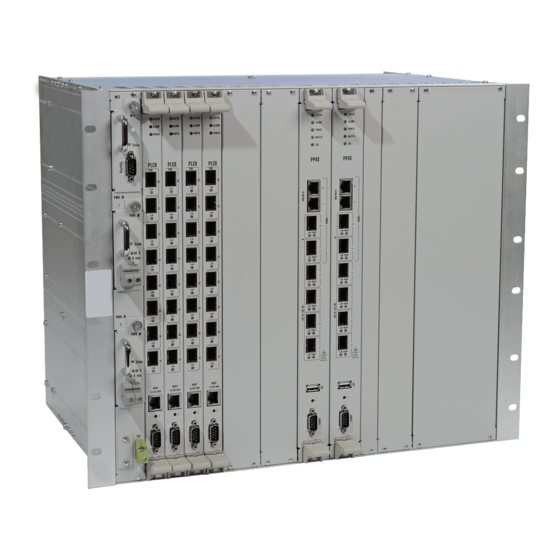
LED indicators and controls. 4.1 Crate MA4000-PX device is metal cased and consists of one 19” crate featuring 9U height. The crate serves for uniting modules of different functional purpose ensuring interaction of modules through high- speed 10 Gbps communication lines as well as for power distribution and supporting and monitoring temperature mode of the entire device. - Page 15 MA4000-PX’s electric power supply system does not include group-type devices, which would determine reliability level of the entire system as a whole. The power supply is arranged by the distribution principle – every module has its own power unit. Herewith the crate functions only as a distributor of power to the modules.
- Page 16 The following designations are used in Figure 5: PLC – GPON interface module; PP4X – central switch module; Env – crate controller. The crate composition depends on the application diagram. The crate features 18 positions for modules installation. PP4X central switch module is mandatory for installation into the crate. Up to two modules of this type can be installed for the sake of ensuring redundancy and increasing system productivity.
- Page 17 1. Signalling connector. The connector is intended for communication with an object, where the equipment is installed, and can be used for connecting various-purpose sensors with “dry contacts” type interface as well for connecting different types of actuators. 2. Two power entry modules. In order to ensure the required level of reliability, the device is furnished with two power entries, which can be connected to two different power sources.
-
Page 18: Pp4X Central Switch Module
4.2 PP4X Central Switch Module Central switch module is the main element of the platform, which generally manages and diagnoses peripheral modules, switching, aggregation and communication interface modules with higher level network equipment. The modules operate in the mode of load sharing and redundancy via two internal 10 Gbps interfaces. - Page 19 — Table 2 PP4X module technical parameters Processor Processor type Marvell MV78x00, ARMv5TE architecture Processor clock frequency 1000 MHz Core quantity Random-access memory DDR2 SDRAM 512 MB 800 MHz 1GB NAND Flash Non-volatile memory 2GB NAND Flash (since version 3v0) Interfaces USB interface Compatible with USB 2.0 specification...
- Page 20 PP4X module current status is displayed by indicators Status, Alarm, Power, Master, SSD Link, Speed. A list of indicator statuses and the values thereof are shown in the following tables: — Table 3 Module status light indicators Indicator Indicator status Device status Green, continuously on Normal operation...
-
Page 21: Gpon Plc8 Interface Module
4.3 GPON PLC8 Interface Module The PLC8 module is designed to organize broadband access to the data network via GPON technology at speeds of up to 2.5 Gbps in the direction to the user. This module is designed for use on the site of the "last mile"... - Page 22 Inter-module connections 1x10/100/1000Base-T RJ45 – Management port 8x 2.5 GPON Console port RS232, 115200 bit/s SFP PON parameters Connector type SC/UPC Receiver sensitivity From -28 to -8 dB Transmission medium Single-mode fibre optical cable SMF 9/125, G.652 Optical power budget 26 dB/24.5 dB (up/downstream) Minimal attenuation...
- Page 23 The module current status of is displayed by indicators Status, Alarm, Power, Link. A list of indicator statuses is shown in Table 7. — Table 7 The device status light indicators Indicator Indicator status Device status Green light on Normal operation Status Red light on The device is loading...
-
Page 24: Ma4000-Px Architecture
5 MA4000-PX ARCHITECTURE MA4000-PX platform is a switching device for Ethernet networks with a distributed switching system. If combined with ONT subscriber devices, MA4000-PX data transmission networks (from its architecture perspective) perform functions relating to access and aggregation levels. MA4000-PX logical structure is shown in Fig. 9. -
Page 25: Pp4X Central Switch Module
5.1 PP4X Central Switch Module Central switch module is the main element of the platform, which generally manages and diagnoses peripheral modules, switching, aggregation and communication interface modules with higher level network equipment. The modules operate in the mode of load sharing and redundancy via two internal 10 Gbps interfaces. - Page 26 PP4X module features: Support for standard management interface through CLI, SNMP interfaces; Processing (changing, storing, archiving) configuration data for all device modules; Aggregate switch functions with the support of the following feature: – MAC address learning/aging; – MAC address quantity restriction;...
-
Page 27: Gpon Plc8 Interface Module
Packet Ethernet processor aggregating GPON transport flows and interacting via high- speed highway of MA4000-PX crate with central switches. In order to ensure device reliability and increase throughput capability, PLC8 module is provided with two interfaces interacting with central switches (uplink) – one for each of them. These interfaces work in aggregated channel mode (trunk or LAG). -
Page 28: Installation And Connection
6 INSTALLATION AND CONNECTION This Section provides safety instructions, procedures for equipment installation into a rack and connection to supply mains. Prior to beginning the work it is necessary to carefully study working instructions and recommendations contained in equipment documentation. Along with the safety requirements specified in this document and other documents accompanying the equipment, all industry relevant laws and regulations as well as operating company’s individual requirements shall be observed when operating the equipment. - Page 29 to connect power supplies, wires with sections corresponding to the maximum value of current used by a device shall be used; adherence to polarity is mandatory when connecting power feeders; available power supplies shall have protective devices to ensure quick load disconnection in case the maximum value for the device feed current had been exceeded;...
-
Page 30: Equipment Installation
6.2 Equipment Installation 6.2.1 Preparations for Installation Prior to equipment installation ensure that mounting location requirements are met. No high temperatures, dust, harmful gases, combustible and explosive materials, sources of intensive electromagnetic radiation (radio stations, transformer substations, etc.), sources of loud sound shall be found at the places of equipment installation. -
Page 31: Rack Mount Installation Of The Device
The above ventilation requirements shall be met when arranging equipment in the cabinet. Figure 13 shows an example for device arrangement in the rack. Fig. 13—Arrangement of MA4000-PX in a Rack User Manual, Part I МA4000-РХ Subscriber Access and Aggregation Point... -
Page 32: Laying And Connecting Cables
6.2.4 Laying and Connecting Cables This Section explains an internal connections order to be made in the telecommunication cabinet. Before connecting power feeders and communication lines to the device, earthing conductors shall be connected first. Telecommunication cabinet shall be earthed prior to perform works on feeding power to the devices. - Page 33 In case of laying optical cable outside the cabinet and leading it into the cabinet, measures shall be taken to protect the cable from damages by means of laying cable in the protective corrugated pipe. Cable bending radius when laying shall be not less than 40 mm. Cable organizers shall be used for horizontal cable laying in the equipment approach area.
-
Page 34: Part Ii Getting Started With The Access Node
PART II GETTING STARTED WITH THE ACCESS NODE User Manual, Part II МA4000-РХ Subscriber Access and Aggregation Point... -
Page 35: Connecting Access Node To Cli
7 CONNECTING ACCESS NODE TO CLI 7.1 Introduction This Chapter describes various connection methods for Command Line Interface (CLI) of the access node. — A serial port (hereafter COM port) is recommended for preliminary adjustment of the access node. 7.2 Connecting to CLI via COM Port This type of connection requires PC either to have an integrated COM port or to be supplied with a USB-COM adapter cable. -
Page 36: Connecting To Cli With Telnet Protocol
******************************************** Welcome to MA4000 ******************************************** ma4000 login: admin Password: ******** Technical support: http://eltex.nsk.ru/support Wed Jan 8 11:58:08 T 2014 ma4000# 7.3 Connecting to CLI with Telnet Protocol The Telnet protocol connection is more flexible than the connection via COM port. Connection to CLI can be established directly at the access node location or via IP network with the help of a remote desktop. - Page 37 Step 4. Log into the terminal CLI. Factory settings: login: admin password: password. ******************************************** Welcome to MA4000 ******************************************** ma4000 login: admin Password: Technical support: http://eltex.nsk.ru/support Mon Jan 13 13:40:02 T 2014 ma4000# User Manual, Part II МA4000-РХ Subscriber Access and Aggregation Point...
-
Page 38: Connecting To Cli With Secure Shell Protocol
Step 3. Log into the access node CLI. Factory settings: login: admin password: password. ******************************************** Welcome to MA4000 ******************************************** ma4000 login: admin Password: Technical support: http://eltex.nsk.ru/support Mon Jan 13 13:40:02 T 2014 User Manual, Part II МA4000-РХ Subscriber Access and Aggregation Point... -
Page 39: Getting Started With The Access Node Cli
8 GETTING STARTED WITH THE ACCESS NODE CLI 8.1 Introduction CLI is the main means of communication between user and the access node. This Chapter considers general operations in CLI. Command Line Interface (CLI) allows to perform the device management and monitor its operation and status. -
Page 40: Command System Structure
To ease and simplify the work with the command line, we have implemented the hotkey support, see Table 10. — Table 10 CLI hotkey description Hotkey Description Ctrl+D In the nested section, return to the previous section ('exit' command); in the root section, exit the CLI ('logout' command). - Page 41 — Fig. 20 Command mode hierarchy The highest command hierarchy level is listed in the Table 11. — Table 11 Command mode hierarchy (the highest level) Previous Level Entry command Help string appearance level Global mode (ROOT) ma4000# МА4000 configuration management ROOT configure terminal ma4000(config)#...
- Page 42 Configuration of PON interfaces located between the Ethernet interface plc-pon-port ma4000 (plc-pon-port-x)# switch and PLC8 module OLT chips (PLC PON-PORT) Configuration of the PLC8 module interface aggregation group used Interface plc-slot-channel ma4000(plc-slot-channel-x)# for connection to the PP4X module. (PLC SLOT-CHANNEL) Configuration of PLC8 module interfaces used for connection to interface plc-slot-port...
-
Page 43: Part Iii Access Node Configuration
PART III ACCESS NODE CONFIGURATION User Manual, Part III Subscriber access/aggregation node МA4000-РХ... -
Page 44: Access Node Configuration
9 ACCESS NODE CONFIGURATION 9.1 Configuration Structure 9.1.1 Introduction A collection of all access node settings is referred to as configuration. This Chapter provides information about the parts configuration consists of. It also defines the lifecycle of configuration and describes main operations which can be performed. 9.1.2 Configuration Structure The access node configuration can be arbitrarily divided into 3 parts. -
Page 45: Creating Configuration Backup
Fig. 22—Diagram of configuration type changes. To apply changes made to the configuration, you should execute the commit command. After that, running configuration becomes backup configuration, and RUNNING is copied to BACKUP. If you need to roll back configuration changes for some reason, perform the rollback operation. After that, the CANDIDATE configuration will be deleted. -
Page 46: Configuration Restore
Step 1. If necessary, define the configuration backup upload on each change (on commit command execution) with the backup onchange command. ma4000(config)# backup onchange Step 2. If necessary, define the configuration backup upload on timer with the backup ontimer command. Set the configuration backup upload timer with the backup ontimer-period command. Pass the timer value in seconds as a parameter. -
Page 47: Network Settings
10 NETWORK SETTINGS 10.1 Introduction This chapter describes adjustment of network settings for an access node. Adjusting network settings enables remote control and integration with OSS/BSS systems. 10.2 Adjustment of Network Settings Adjustments of network settings are recommended to be done via COM port connection, described under 7.2 Connecting to CLI via COM Port. -
Page 48: User Management
11 USER MANAGEMENT 11.1 Introduction This Chapter is devoted to management of the access node users. The factory settings provide only for one user, i.e. the device administrator. login: admin password: password When you start to configure the access node, we recommend you to change the password of the "admin"... -
Page 49: User List Preview
11.2 User List Preview In order to view the user list, use the show users config command: ma4000# show users config System users ~~~~~~~~~~~~ User name User privilege level -------------------- ---------------------------------------- root admin remote linux 4 system users. The "admin", "root" and "linux" users always exist and cannot be deleted or duplicated. The access node supports up to 16 users. -
Page 50: Viewing And Changing User Access Rights
11.5 Viewing and Changing User Access Rights To manage user access rights, user priority system is implemented. When a user is created, minimal rights are delegated to him: ma4000(config)# user operator ma4000(config)# do show users System users ~~~~~~~~~~~~ User name User privilege level -------------------- ----------------------------------------... -
Page 51: User Authentication Configuration
11.8 User Authentication Configuration There are several methods of user authentication in the system: do not use the authentication; local — use local user database for authentication; tacacs+ — use TACACS+ server for authentication; radius — use RADIUS server for authentication; Step 1. -
Page 52: Service Configuration
12 SERVICE CONFIGURATION 12.1 SNMP Configuration Step 1. Enable SNMP agent using the ip snmp agent enable command: ma4000(config)# ip snmp agent enable Step 2. Define the SNMP device name using the ip snmp agent system name command: ma4000(config)# ip snmp agent system name ma4000 Step 3. -
Page 53: Ssh Configuration
Step 3. Define the quantity of system log files of the same type. ma4000(config)# logging max-files 5 Step 4. If necessary, perform the message level configuration for the files listed in the Table 25. ma4000(config)# logging file pp debug Step 5. If necessary, perform the message filter configuration for the files listed in the Table 25 using the match command. -
Page 54: Tacacs/Tacacs+ Configuration
12.5 Tacacs/Tacacs+ Configuration Step 1. Define the Tacacs server connection settings. ma4000(config)# tacacs-server timeout 10 ma4000(config)# tacacs-server key 12345 ma4000(config)# tacacs-server encrypted key 98C7D37909 Step 2. Add Tacacs server into the list of utilized servers using the tacacs-server host command. Define the connection settings for this server. -
Page 55: Sntp Configuration
12.7 SNTP Configuration Step 1. Enable time synchronization using the ip sntp client command. ma4000(config)# ip sntp client Step 2. Define the time synchronization server IP address using the ip sntp server command: ma4000(config)# ip sntp server 192.168.1.254 Step 3. Specify the synchronization interval in minutes: ma4000(config)# ip sntp poll-period 60 Step 4. -
Page 56: Vlan Configuration
13 VLAN CONFIGURATION 13.1 Introduction This Chapter describes VLAN configuration in the access node. VLAN (Virtual Local Area Network) is a group of devices which communicate on channel level and are combined into a virtual network that is connected to one or more network devices (GPON terminals or switches). -
Page 57: Deleting A Vlan
Step 4. Enable IGMP snooping by using the ip igmp snooping slot <slot> enable command if necessary. ma4000(vlan-100)# ip igmp snooping slot 0-15 enable ma4000(vlan-100)# ip igmp snooping pp4x enable Step 5. Enable IGMP querier by using the ip igmp snooping querier enable command if necessary. ma4000(vlan-100)# ip igmp snooping querier enable Step 6. -
Page 58: Pp4X Stacking Configuration
14 PP4X STACKING CONFIGURATION If two PP4X modules are used , their configuration files will be synchronized. If PP4X master fails, PP4X slave will keep the running configuration. The no stack sync-allow command allows to disable the configuration file synchronization for the stack. -
Page 59: Interfaces Configuration
15 INTERFACES CONFIGURATION 15.1 Introduction This Chapter describes the configuration of the access node interfaces. Access node interfaces can be divided into two groups: Ethernet interfaces and GPON interfaces. Ethernet interfaces are used for access node connection to operator's network core. GPON interfaces are used for ONT connections. -
Page 60: Ethernet Interfaces Configuration
PLC8 module interface LAG for Specified as: S/P plc-slot-channel connection to central switches—PP4X S—PLC8 module number [0..15] modules P—channel number for module [0] Specified as: S/P PLC8 module external management plc-front-port S—PLC8 module number [0..15] interface (mgmt) P—channel number for module [0] Specified as: S P PLC8 switch falling interface, connected S—PLC8 module version [0 .. -
Page 61: Gpon Interfaces Configuration
Step 7. Adjust time settings of optical transceiver if needed. ma4000(config)(if-gpon-0-7)# optics use-custom ma4000(config)(if-gpon-0-7)# optics ... Optical transceiver should be adjusted only by agreement with Eltex Service Center. Step 8. Apply the configuration by using the commit command. ma4000(config)(if-gpon-0-7)# do commit User Manual, Part III Subscriber access/aggregation node МA4000-РХ... -
Page 62: Isolation Group Configuration
16 ISOLATION GROUP CONFIGURATION 16.1 Introduction Isolation group is the mechanism, that allows to restrict the traffic flow inside the VLAN. Isolation groups allow to configure one-way data transmission or divide interfaces located inside the VLAN into 2 logical groups. Operating principle is shown in Fig. 24. Fig. - Page 63 Step 4. Go to the configuration mode for the required VLAN: ma4000(pp4x-config-isolation-1)# exit ma4000(config)# vlan 100 Step 5. Enable isolation with the isolation enable command: ma4000(vlan-100)# isolation enable Step 6. Enable the data transmission from the specific interface to the isolation group (destination interfaces) using the isolation assign command.
-
Page 64: Selective Q-In-Q Configuration
17 SELECTIVE Q-IN-Q CONFIGURATION 17.1 Introduction SELECTIVE Q-IN-Q function allows to assign external SPVLAN (Service Provider's VLAN), substitute Customer VLAN, and block the transmission of traffic based on configured filtering rules by internal VLAN numbers (Customer VLAN). 17.2 Selective Q-in-Q Configuration Step 1. -
Page 65: Qos Configuration
18 QOS CONFIGURATION The traffic prioritization method will be chosen depending on the configured system rules (IEEE 802.1p/DSCP). — Table 15 Traffic prioritization methods Priority Description All priorities are equal Packet selection is based on IEEE 802.1p standard Packet selection is based on IP ToS (type of service) at the level 3 only—Differentiated Services Codepoint (DSCP) support Interactions based on 802.1p or DSCP/TOS Step 1. -
Page 66: Lag Configuration
19 LAG CONFIGURATION 19.1 Introduction This Chapter describes configuration of uplink interfaces aggregation. Link aggregation (IEEE 802.3ad) is a technology that allows multiple physical links to be combined into one logical link (aggregation group). Aggregation group has high throughput and is very reliable. Fig. -
Page 67: Lag Configuration
19.2 LAG Configuration LAG configuration represents static aggregation configuration or LACP configuration. To configure LAG, perform the steps marked blue in figure 26. LACP configuration requires all steps to be performed. — Fig. 26 LAG and LACP Configuration Procedure Step 1. Create a port-channel logical interface by using the interface port-channel command. As a parameter, pass the number of the interface being created. - Page 68 Step 4. This step should only be performed for LACP configuration. Set a LACP system priority by using the lacp system-priority command. The no lacp system-priority command returns 32768 by default. ma4000(express-config-port-channel-1)#exit ma4000(config)# lacp system-priority 32768 Step 5. Specify load balance rules with the help of the "port-channel load-balance" command if needed.
-
Page 69: Spanning Tree Configuration
20 SPANNING TREE CONFIGURATION 20.1 Introduction Spanning Tree Protocol (STP) is a network protocol. The main task of STP is to eliminate loops in the arbitrary Ethernet network topology with one or multiple network bridges connected with redundant links. STP solves this task by automatically blocking connections that are redundant for the full switch interconnection at the given moment of time. - Page 70 — filtering packets are filtered for the interface with STP BDPU protocol disabled — flooding untagged BDPU packets are transmitted for the interface with STP protocol disabled, tagged packets are filtered ma4000(config)# spanning-tree bpdu flooding Step 8. Define the maximum quantity of BDPU packets, that could be received by the device in a second of time, using the spanning-tree holdcount command: ma4000(config)# spanning-tree holdcount 5 Step 9.
-
Page 71: Dual Homing Configuration
21 DUAL HOMING CONFIGURATION 21.1 Introduction The operating principle of Dual Homing technology is similar to the Spanning Tree technology. However, the Spanning Tree technology has a major disadvantage. If there are more than 7 computers in a network, fault identification and performance restoration can take up to several minutes. During this time, the network will not be available. -
Page 72: Lldp Configuration
22 LLDP CONFIGURATION 22.1 Introduction Link Layer Discovery Protocol (LLDP) is a data-link level protocol, that allows network devices to announce the information on their essence and capabilities into the network and gather such information from the neighbouring devices. 22.2 LLDP Configuration Step 1. -
Page 73: Multicast Configuration
23 MULTICAST CONFIGURATION 23.1 Introduction The Chapter describes peculiarities of IPTV service configuration. Internet Group Management Protocol (IGMP) and MLD (Multicast Listener Discovery) are used in hosts and routers for multicasting support. It provides all systems of a physical network with relevant information: which hosts are included in groups and which group corresponds to a host. -
Page 74: Multicast Configuration
— Fig. 28 IGMP Snooping Is Enabled As you may see from Fig. 28, access node with enabled IGMP snooping translates multicast traffic only to those trees, that have sent the IGMP group connection request. IGMP proxy is an IGMP client and group router at the same time (IGMP router). On the one hand, proxy requests an upstream router for group channels;... -
Page 75: Ipv6 Multicast Configuration
ma4000(vlan-100)# ip igmp snooping querier enable Step 5. Define processing policy for the unrequested multicast traffic: ma4000(vlan-100)# exit ma4000(config)# ip igmp unregistered ip4-mc drop Step 6. If necessary, enable IGMP proxy: ma4000(config)# ip igmp proxy report pp4x enable Step 7. Define the rules for proxying from one VLAN into another. Pass the group range, source vlan, and destination vlan as parameters. - Page 76 Step 7. Define rules for proxying between VLANs. As an argument, transmit a range of groups, vlan-source and vlan-receiver. ma4000(config)# ipv6 mld proxy report range ff15:: ff15::ffff from all to 30 Step 8. Apply the configuration, using commit command. ma4000(config)# do commit User Manual, Part III Subscriber access/aggregation node МA4000-РХ...
-
Page 77: Dhcp Relay Agent Configuration
24 DHCP RELAY AGENT CONFIGURATION 24.1 Introduction This Chapter describes configuration of DHCP Relay Agent in the terminal. DHCP Relay Agent is used to provide a DHCP server with additional information about a received DHCP request. This may include information about the access node running DHCP Relay Agent as well as information about ONT which sent the DHCP request. - Page 78 %SLOTID% The number of MA4000 slot %DESCR% Description of ONT In addition to DHCP option, DHCP Relay Agent has some more functions related to network security. It provides protection from DoS attacks by setting a threshold for intensity of DHCP messages which are received from ONT.
-
Page 79: Dhcp Relay Agent Profiles Management
24.2 DHCP Relay Agent Profiles Management A set of profiles is used for DHCP Relay Agent configuration. All VLANs use profile dhcp-ra-00 by default. The configuration is flexible as it allows DHCP profiles to be assigned not only to a slot MA4000, but separately to each VLAN as well. -
Page 80: Dhcp Relay Agent Profiles Configuration
24.3 DHCP Relay Agent Profiles Configuration Step 1. Switch to the corresponding DHCP Relay Agent profile. ma4000(config)# profile dhcp-ra dhcp-ra-01 Step 2. Enable DHCP traffic processing with the enable command. ma4000(config-dhcp-ra)("dhcp-ra-01")# enable Step 3. Enable insert/overwrite of DHCP option 82 with the help of the overwrite-option82 command if needed. -
Page 81: Dhcpv6 Relay Agent Profiles Management
24.4 DHCPv6 Relay Agent profiles management DHCPv6 Relay Agent configuration is performed via profiles system. By default, dhcp-ra-00 profile is used for all VLANs. The flexibility of configuration provides opportunity to assign DHCPv6 profiles not only for MA4000 slot, but for specified VLAN individually. The assignment is implemented in several steps. Step 1. -
Page 82: Dhcp Broadcast-To-Unicast Relay Agent Configuration
ma4000(config-dhcp-ra)("dhcp-ra-01")# add-suboptions Step 4. If necessary, define DHCPv6 option 37 and 38 formats, using add-remote-id and add- interface-id commands. The list of tokens is represented in Table 19. ma4000(config-dhcpv6-ra)("dhcp-rav6-01")# add-interface-id "%PONSERIAL%" ma4000(config-dhcpv6-ra)("dhcp-rav6-01")# add-remote-id "%OPT82_RID%" Step 5. If necessary, activate protection against DoS attacks, using dos-block command. Set the threshold of DHCP request rate. -
Page 83: Pppoe Intermediate Agent Configuration
25 PPPOE INTERMEDIATE AGENT CONFIGURATION 25.1 Introduction This Chapter describes configuration of PPPoE Intermediate Agent of the access node. PPPoE Intermediate Agent is used to provide BRAS with additional information about a received PADI request. This may include information about the terminal running PPPoE Intermediate Agent as well as information about ONT which sent the PADI request. - Page 84 ma4000(config)# profile pppoe-ia pppoe-ia-00 ma4000(config-pppoe-ia)("pppoe-ia-00")# Step 2. Enable PPPoE traffic processing with the enabled command. ma4000(config-pppoe-ia)("pppoe-ia-00")# enable Step 3. Specify the vendor specific tag format with the help of the format circuit-id and format remote-id commands. A list of possible tokens is given in Table 20. ma4000(config-pppoe-ia)("pppoe-ia-00")# format circuit-id "%HOSTNAME%"...
-
Page 85: Ip Source Guard Configuration
26 IP SOURCE GUARD CONFIGURATION 26.1 Introduction IP Source-Guard allows limiting unauthorized using of IP addresses (by binding IP and MAC addresses of a source to a specific service on a specific ONT). There are two operation modes: Static. You need to strictly define correspondence of MAC and IP addresses of a client device for transmitting traffic from the client. - Page 86 ma4000(config)# ip source-guard bind ip <IP> mac <MAC> interface-ont <ONT> service <NUM> Where: IP – IP address of client equipment in X.X.X.X format, МАС – MAC address of client equipment in ХХ:XX:XX:XX:XX:XX format, ONT – ONT identifier in SLOT_ID/CNANNEL_ID/ONT_ID format, NUM –...
-
Page 87: Part Iv Ont Configuration
PART IV ONT CONFIGURATION User Manual, Part IV Subscriber access/aggregation node МA4000-РХ... -
Page 88: Service Models
27 SERVICE MODELS This Chapter considers main terms and classification of service models. 27.1 Introduction In general, a service model is based on a method which describes how the services are provided: "VLAN for Subscriber" or "VLAN for Service". The "VLAN for Service" architecture means that a service VLAN (S-VLAN) is used to provide all users with a certain service. -
Page 89: Vlan For Service" Architecture
27.1.2 "VLAN for Service" Architecture S-VLAN model has a separate VLAN for every service. Consider its operation on an example of an abstract S-VLAN 100 service. S-VLAN 100 is used between OLT and service routers that is global for all subscribers in terms of this service. -
Page 90: Model 1
— Table 21 Service Models VLAN for Broadcast to Dedicated Broadcast VLAN for Service Subscriber Unicast GEM Model 1 Model 2 Model 3 27.2.1 Model 1 Consider a model 1 implementation example. The chart of this service model is shown in Fig. 31. Fig. -
Page 91: Model 2
27.2.2 Model 2 Consider a model 2 implementation example. The chart of this service model is shown in Fig. 32. Fig. 32—Service Model 2 Chart A S-VLAN is used between ONT and service routers (BRAS, VoIP SR) that encapsulate services for one subscriber (one ONT), such as VoIP, Internet, and IPTV unicast. -
Page 92: Model Configuration
Dedicated S-VLANs are used between OLT and service routers (BRAS, VoIP SR) for each of the following services: VoIP, Internet, IPTV unicast, and TR-069. These S-VLAN are global for all subscribers (ONT). Corresponding GEM ports are created for every OLT service between ONT and OLT. A dedicated MC-VLAN is used for multicast transmissions. - Page 93 Multicast gem port: 4094 Encryption: Enable: false Key update interval: ONT authentication mode: both Auto reconfigure ont: true Auto reconfigure channel: true Auto reconfigure olt: true Ont sn format: literal Step 2. Set model by using the gpon olt model command. ma4000# configure terminal ma4000(config)# gpon olt model 1 Step 3.
-
Page 94: Ont Configuration
28 ONT CONFIGURATION 28.1 Introduction This Chapter describes general principles of ONT configuration. It also defines configuration profiles. ONT is configured with the help of a profile which defines high-level expression of data communication channels. All operations related to channel creation are performed automatically. The way the data communication channels are created depends on the selected service model (see Chapter 27 Service Models, page 88). - Page 95 Fig. 34—ONT Scope of Operation User Manual, Part IV Subscriber access/aggregation node МA4000-РХ...
-
Page 96: Ont Profiles Configuration
28.3 ONT Profiles Configuration 28.3.1 Cross-Connect Profile Configuration Step 1. To configure a cross-connect profile, you need first to specify whether the service will be routed (transmitted through an ONT router) or bridged (use bridge connection). This can be done by changing the model parameter. -
Page 97: Ports Profile Configuration
28.3.4 Ports Profile Configuration The "ports" profile allows you to group ports in ONT. The profile also contains IGMP and multicast setting as they are separately adjusted for each port. You can adjust up to 4 Ethernet ports and a VEIP virtual port which will serve as a link between OMCI and RG domains in ONT. -
Page 98: Ont Configuration Procedure
28.4 ONT Configuration Procedure Figure 35 shows steps of ONT configuration. Fig. 35—ONT Configuration Procedure Step 1. Prior to proceed to ONT configuration, add the ONT into an OLT configuration. For an ONT to be added and configured, it does not need to physically connected to OLT. You can view the list of unactived ONTs with the help of the show interface ont unactivated command: ma4000# show interface ont 0/0/0 unactivated Slot 0 GPON-port 0 has no unactivated ONTs... - Page 99 ma4000(config)(if-ont-0/0/0)# do show interface ont 0/0/0 configuration ----------------------------------- [ONT0/0] configuration ----------------------------------- Description: Status: Serial: 0000000000000000 Password: Fec up: false Downstream broadcast: true Ber interval: 100000 Ber update period: Rf port state: no change Omci error tolerant: false Service [0]: Profile cross connect: crossconnect-00 ONT Profile Cross Connect 0...
-
Page 100: Model 1
28.4.1 Model 1 Consider configuration of a data communication channel which is based on model 1 and implements "VLAN for Subscriber". Figure 36 shows a configuration of two abstract services with subscriber C-VLAN 200 and U-VLAN 10 and 11 for each service correspondingly. Fig. - Page 101 Step 5. Check the amendments made. ma4000(config-cross-connect)("service2")# do show profile cross-connect service2 Name: 'service2' Description: 'ONT Profile Cross Connect Model: Bridge group: Tag mode: single-tagged Outer vid: Outer cos: unused Inner vid: U vid: untagged U cos: unused Mac table entry limit: unlimited Type: general...
- Page 102 First group ip: 0.0.0.0 Last group ip: 0.0.0.0 Multicast dynamic entry [1]: Vlan id: unused First group ip: 0.0.0.0 Last group ip: 0.0.0.0 Multicast dynamic entry [2]: Vlan id: unused First group ip: 0.0.0.0 Last group ip: 0.0.0.0 Multicast dynamic entry [3]: Vlan id: unused First group ip:...
- Page 103 Fec up: false Downstream broadcast: true Ber interval: 100000 Ber update period: Rf port state: no change Omci error tolerant: false Service [0]: Profile cross connect: Service1 Profile Cross Connect 4 Profile dba: AllServices Profile DBA 2 Service [1]: Profile cross connect: Service2 Profile Cross Connect 3 Profile dba:...
-
Page 104: Model 2
Profile dba: AllServices Profile DBA 2 Custom vlan: Custom CoS: unused Service [1]: Profile cross connect: Service2 Profile Cross Connect 3 Profile dba: AllServices Profile DBA 2 Custom vlan: Custom CoS: unused … Step 12. Apply the changes by using the commit command. ma4000(config)(if-ont-0/0/0)# do commit Step 13. - Page 105 ma4000(config)# profile cross-connect Service3 ma4000(config-cross-connect)("Service3")# bridge ma4000(config-cross-connect)("Service3")# bridge group 1 Step 3. To assign an S-VLAN, use the outer vid 30 command. ma4000(config-cross-connect)("Service3")# outer vid 30 Step 4. Specify U-VID in order to have untagged traffic coming from the ONT port. ma4000(config-cross-connect)("Service3")# user vid untagged Step 5.
- Page 106 ma4000(config-ports)("Ports1")# do show profile ports Ports1 Name: 'Ports1' Description: 'ONT Profile Ports 1' … Port [0]: Bridge group: Spanning tree for bridge group: false Multicast enable: false Multicast port settings: Upstream igmp vid: Upstream igmp prio: Upstream igmp tag control: pass Downstream multicast vid: Downstream multicast prio:...
-
Page 107: Tunnelling Configuration
Service [6]: Profile cross connect: unassigned Profile dba: unassigned Service [7]: Profile cross connect: unassigned Profile dba: unassigned Profile shaping: shaping-00 Profile Shaping 0 Profile ports: Ports1 Profile Ports 1 Profile management: management-00 Profile Management 0 Profile scripting: unassigned Custom model: none Template: unassigned... - Page 108 Fig. 38 - The scheme of connection VLAN 300 (multicast) and QinQ VLAN 1100 and 1200 (the Internet) come to the uplink OLT. It is necessary to let them pass to the switch integrated in the OLT via SFP-ONU. In addition, a corporate client is connected to the splitter via SFP-ONU that sends a random set of VLANs to be passed to remote devices after removing tags of these VLANs at the ONT LAN port.
- Page 109 tagged plc-pon-port 0/0 tagged front-port 1/0 exit vlan 1200 name VLAN1200 tagged plc-pon-port 0/0 tagged front-port 1/0 exit Step 2. Set up cross-connect profiles. profile cross-connect "cc-tunnel" bridge bridge group "10" tag-mode tunnel exit profile cross-connect "cc-selecttunnel" bridge bridge group "10" tag-mode selective-tunnel exit profile cross-connect "cc-single"...
- Page 110 0 custom cvid "20" service 0 custom svid "500" Tunnel and selective-tunnel services are supported only on Eltex SFP-ONU at the moment of MA4000 3.26.0 release. The quantity of uvid processed by selective-tunnel services on a single ONT should not exceed 42.
-
Page 111: Dba Configuration
29 DBA CONFIGURATION 29.1 Introduction This Chapter considers DBA configuration for ONT. GPON technology implies that all ONTs of one GPON channel use common communication medium (fibre). It is necessary to provide a mechanism that will ensure data transfer from all ONTs without collisions. - Page 112 — Table 23 Alloc Profile Configuration and T-CONT types T-CONT T-CONT T-CONT T-CONT T-CONT type 1 type 2 type 3 type 4 type 5 service-class voip type5 type5 type5 status-reporting fixed-bandwidth guaranteed-bandwidth besteffort-bandwidth The following rules apply to dba profile assignment: —...
-
Page 113: Dba Profiles Assignment
29.2 DBA Profiles Assignment 29.2.1 Services in Different T-CONTs Two Alloc-IDs will be allocated in an OLT for an ONT. Each service will operate in its allocation. There will be two T-CONT on the ONT side corresponding to the allocations. Step 1. -
Page 114: Services In One T-Cont
29.2.2 Services in One T-CONT One Alloc-ID will be allocated in an OLT for an ONT. One T-CONT will be configured in the ONT. The T-CONT will be used to transfer traffic from multiple services. Traffic priority will be based on the value of the "priority-queue"... -
Page 115: Profiles Assignment Example
You will have the following ONT configurations: ma4000(config)(if-ont-0/0/0-1)# do show interface ont 0/0/0-1 configuration ----------------------------------- [ONT0/0/0] configuration ----------------------------------- … Service [0]: Profile cross connect: Service1 ONT Profile Cross Connect 4 Profile dba: ServiceInternet ONT Profile DBA 3 Custom vlan: Custom CoS: unused …... -
Page 116: Dba Configuration
----------------------------------- … Service [0]: Profile cross connect: Service1 ONT Profile Cross Connect 4 Profile dba: ServiceVoIP ONT Profile DBA 4 Custom vlan: Custom CoS: unused Service [1]: Profile cross connect: Service2 ONT Profile Cross Connect 3 Profile dba: ServiceVoIP ONT Profile DBA 4 Custom vlan: Custom CoS: unused... -
Page 117: T-Cont Type 2 Configuration
ma4000(config-dba)("dba-00")# do show profile dba dba-00 Name: 'dba-00' Description: 'ONT Profile DBA 0' Dba: Sla data: Service class: Status reporting: Alloc size: Alloc period: Fixed bandwidth: 100000 Guaranteed bandwidth: Besteffort bandwidth: Step 5. Apply the changes by using the do commit command. ma4000(config-dba)("dba-00")# do commit 29.3.2 T-CONT Type 2 Configuration Consider configuration of a 100 Mbps guaranteed bandwidth. -
Page 118: T-Cont Type 3 Configuration
29.3.3 T-CONT Type 3 Configuration Consider configuration of a 100 Mbps guaranteed bandwidth with a possibility of allocation of a 200 Mbps best-effort bandwidth. Step 1. Specify a T-CONT type by using the sla class command. ma4000(config)# profile dba dba-00 ma4000(config-dba)("dba-00")# sla class type5 Step 2. -
Page 119: T-Cont Type 5 Configuration
Step 2. Specify a type of status reports for ONT queues by using the sla status-reporting command. ma4000(config-dba)("dba-00")# sla status-reporting nsr Step 3. Set best-effort bandwidth parameters by using the bandwidth besteffort command. Set other bandwidth parameters to 0. The bandwidth has a value in Kbps (1000 bps) and is not rounded down to 64 Kbps. ma4000(config-dba)("dba-00")# bandwidth fixed 0 ma4000(config-dba)("dba-00")# bandwidth guaranteed 0 ma4000(config-dba)("dba-00")# bandwidth besteffort 200000... - Page 120 The bandwidth has a value in Kbps (1000 bps) and is not rounded down to 64 Kbps. ma4000(config-dba)("dba-00")# bandwidth fixed 100000 ma4000(config-dba)("dba-00")# bandwidth guaranteed 200000 ma4000(config-dba)("dba-00")# bandwidth besteffort 1244000 Step 4. Use the "show" command to check the parameters. ma4000(config-dba)("dba-00")# do show profile dba dba-00 Name: 'dba-00' Description:...
-
Page 121: Rg Ont Configuration
30 RG ONT CONFIGURATION 30.1 Introduction This Chapter considers issues related to configuration of Residential Gateway (RG) ONT. The Chapter uses the terms of "bridges" and "routed" services. Consider the concept of OMCI and RG management domains. These terms are defined in TR-142 Issue 2. -
Page 122: Services Combined Configuration
ONT is connected to RG using a Virtual Ethernet interface point (VEIP), which corresponds to TR- 069 WAN interface (described in TR-098) on RG the side. VEIP is represented by a virtual port in access node parameters. The port has the same configuration procedure as Ethernet ports in the "ports" profile. - Page 123 Step 3. Create cross-connect profiles for services. ma4000(config)# profile cross-connect RG-service ma4000(config-cross-connect)("RG-service")# exit ma4000(config)# profile cross-connect OMCI-service ma4000(config-cross-connect)("OMCI-service")# ma4000(config-cross-connect)("OMCI-service")# exit Step 4. Create an dba profile. DBA parameters are not important for the purposes set forth in this Chapter, so we will not configure DBA here and simply use default values. We will also assign one profile to both services that means that upstream services will operate with one T-CONT.
- Page 124 ma4000(config-ports)("2RG-2OMCI")# port 1 bridge group 0 ma4000(config-ports)("2RG-2OMCI")# port 2 bridge group 1 ma4000(config-ports)("2RG-2OMCI")# port 3 bridge group 1 Step 9. Create an ONT configuration. ONT management is described in details in Chapter 28 ONT Configuration, page 94. ma4000(config)# interface ont 0/0/0 ma4000(config)(if-ont-0/0/0)# Step 10.
-
Page 125: High Speed Internet Configuration
31 HIGH SPEED INTERNET CONFIGURATION Configuration of the High Speed Internet (HSI) service does not have any peculiarities and can be easily performed as described in Chapter 28 ONT Configuration, page 94. User Manual, Part IV Subscriber access/aggregation node МA4000-РХ... -
Page 126: Multicast Configuration
32 MULTICAST CONFIGURATION 32.1 Introduction The Chapter describes peculiarities of multicast service configuration for model 1 and model 3. 32.2 Model 1 Multicast Configuration Let us configure a multicast service for model 1. An STB, which works in VLAN 14, is connected to an ONT port in this example. Upstream IGMP packets arrive at VLAN 14 though a GEM port and the OLT changes VLAN 14 to subscriber's VLAN 200. - Page 127 Name: 'UsIGMP' Description: 'ONT Profile Cross Connect Model: Bridge group: Tag mode: single-tagged Outer vid: Outer cos: unused Inner vid: U vid: U cos: unused Mac table entry limit: unlimited Type: general Iphost eid: Priority queue: Step 4. Associate a bridge port with an ONT port. To do this, create a "ports" profile and assign value 1 to the "bridge group"...
- Page 128 Shaper downstream: Enable: false Commited rate: 1000000 Shaper upstream: Enable: false Commited rate: 1000000 Commited rate: 1000000 Step 7. Assign the created profiles in ONT. Configure a custom-cross-connect profile, specify C- VLAN 200 and apply the configuration: ma4000(config)# interface ont 0/0/0 ma4000(config)(if-ont-0/0/0)# service 0 profile cross-connect UsIGMP ma4000(config)(if-ont-0/0/0)# profile ports Ports1 ma4000(config)(if-ont-0/0/0)# service 0 custom cvid 200...
-
Page 129: Model 2 (3) Multicast Configuration
32.3 Model 2 (3) Multicast Configuration Let us configure a multicast service for model 3. The multicast service operates in VLAN 98 in our example, an STB operating in VLAN 14 is connected to an ONT port. Upstream IGMP packets come to VLAN 14 in the ONT where VLAN 14 is replaced with VLAN 98, and then the data is further transferred upstream through the GEM port. - Page 130 Step 4. Associate a bridge port with an ONT port. To do this, create a "ports" profile and assign value 1 to the "bridge group" parameter for the LAN1 port: ma4000(config)# profile ports Ports1 ma4000(config-ports)("Ports1")# port 1 bridge group 1 Step 5.
- Page 131 Step 8. Add VLAN 98 and enable IGMP snooping: ma4000(config)# vlan 98 ma4000(vlan-98)# tagged plc-front-port 0/0 ma4000(vlan-98)# tagged plc-pon-port 0/0-7 ma4000(vlan-98)# ip igmp snooping enable ma4000(vlan-98)# exit ma4000(config)# ip igmp snooping enable ma4000(config)# do commit User Manual, Part IV Subscriber access/aggregation node МA4000-РХ...
-
Page 132: Voip Configuration
33 VOIP CONFIGURATION 33.1 Introduction The Chapter describes peculiarities of VoIP service configuration. The access node supports several methods of VoIP configuration: VoIP configuration in OMCI management domain; VoIP configuration in RG management domain. A methods is chosen based on service model and ONT functionality. 33.2 VoIP Configuration in OMCI Management Domain VoIP is a special bridged service. -
Page 133: Voip Configuration In Rg Management Domain
33.3 VoIP Configuration in RG Management Domain In case a VoIP client is located after the U point (i. e. in an RG management domain), a VoIP service has the same configuration procedure as all other routed services. The procedure is described in details in Chapter 28 ONT Configuration, page 94. -
Page 134: Protocol Management Configuration
34 TR-069 PROTOCOL MANAGEMENT CONFIGURATION 34.1 Introduction This Chapter describes configuration of data communication channel for a CPE management service via the TR-069 protocol. Two modes are available to establish an ONT management channel: Inband and OutOfBand. Inband is a preferred mode as it is simpler. Contact your ONT vendor for information about operation capabilities of both modes. -
Page 135: Configuration Of A Tr-069 Oob Management Channel
Step 2. Set the "IP Host" identifier to 0. ma4000(config-cross-connect)("TR069")# iphost eid 0 Step 3. Check the changes. ma4000(config-cross-connect)("TR069")# do show profile cross-connect TR069 Name: 'TR069' Description: 'ONT Profile Cross Connect Model: ont-rg Bridge group: Tag mode: single-tagged Outer vid: Outer cos: unused Inner vid:... -
Page 136: Client Configuration
Step 1. Set the "management" type in the "cross-connect" profile. ma4000(config)# profile cross-connect TR069 ma4000(config-cross-connect)("TR069")# type management Step 2. Set the "ont" model of the "cross-connect" profile. Specify a separate bridge-group. ma4000(config-cross-connect)("TR069")# bridge ma4000(config-cross-connect)("TR069")# bridge group 20 Step 3. Set the "IP Host" identifier to 0. ma4000(config-cross-connect)("TR069")# iphost eid 0 Step 4. - Page 137 ma4000# configure terminal ma4000(config)# profile management management-00 ma4000(config-management)("management-00")# omci-configuration Step 2. Specify connection parameters. ma4000(config-management)("management-00")# url http://acs/tele/com:9595/acs ma4000(config-management)("management-00")# username acs ma4000(config-management)("management-00")# password acsacs Step 3. Check the changes. ma4000(config-management)("management-00")# show profile management management-00 Name: 'management-00' Description: 'ONT Profile Management 0' Enable omci configuration: true Url:...
-
Page 138: Ont Configurations Templates
35 ONT CONFIGURATIONS TEMPLATES 35.1 Introduction It is not always convenient, especially for large scale operators, to build ONT configuration from separate profiles for each subscriber. This process is painstaking and risky in a certain sense as it is highly prone to operator error. -
Page 139: Ont Configuration Preview With Templates
ma4000(config)# interface ont 0/0/0-10 ma4000(config)(if-ont-0/0/0-10)# Step 2. Assign configuration template to ONT by using the template command. ma4000(config)(if-ont-0/0/0-10)# template HSI-100-CaTV Step 3. Define individual ONT parameters not specified in the template, if necessary. ma4000(config)(if-ont-0/0/0-10)# rf-port-state enabled Step 4. Apply the changes made ma4000(config)(if-ont-0/0/0-10)# do commit 35.4 ONT Configuration Preview with Templates ONT configuration viewing is performed by using the show interface ont <id>... -
Page 140: Ont Licensing
ONT LICENSING 36.1 Introduction By default, the operation with OLT is enabled only for ONT made by Eltex. For other ONTs, you need to activate a license. Please, contact a commercial department of Eltex to obtain a license. If a third-party ONT is connected to OLT without a license, the following entry will... - Page 141 – the full content of the license file, including curly braces. For viewing the information on uploaded license, use 'show' command: ma4000# show license Active license information: License valid: Version: Carrier: Eltex Enterprise LLC Licensed vendor: Licensed ONT count: unlimited Licensed ONT online: OL02000000 Mac: A8:F9:4B:00:00:00 The license file is saved while restarting, firmware updating and configuration uploading.
-
Page 142: Part V Access Node Monitoring
PART V ACCESS NODE MONITORING User Manual, Part V Subscriber access/aggregation node МA4000-РХ... -
Page 143: General Information
Temperature (SFP): 35C Temperature (CPU): 42C Temperature (Switch) : 49C Firmware version: 3.22.0.189 r39940 05:32:45 04/09/2014 Linux version: Linux version 2.6.22.18 (alexey.vlasov@turbo.eltex.loc) (gcc version 4.3.2 (sdk3.2rc1-ct-ng-1.4.1) ) #1 Thu Sep 4 12:02:21 NOVT 2014 MAC address: a8:f9:4b:88:33:a0 Serialnumber: OL02000580 To view information about the crate, show system environment command shall be used. -
Page 144: Interface Module Status View
RPM: 1524 1554 1560 Feeder1 Feeder2 Status: REVERSED ok Current, A: 0.00 1.00 Voltage, V: 1.92 -53.69 Shelfvoltage, V: -54.35 37.3 Interface Module Status View To view information about interface modules, show shelf command shall be used. ma4000# show shelf Shelf status ~~~~~~~~~~~~ Slot #... -
Page 145: Access Node Run-Time Log
38 ACCESS NODE RUN-TIME LOG To view a list of logs, show log command shall be used: ma4000# show log Log files ~~~~~~~~~ Name Size in bytes Date of last modification ---- -------------------- ---------------- ------------------------- daemon Thu Sep 11 16:59:14 2014 126432 Thu Sep 11 16:59:46 2014 ----... -
Page 146: Active Alarms Log
39 ACTIVE ALARMS LOG 39.1 Introduction The system of logging is built on a central application systemdb, which organizes interfaces to events database (DB). All emerging events both from interface boards and PP4X switch itself are sent into systemdb to be saved in the base. All events are divided into 2 types: one-time and state changing events. -
Page 147: Alarms
39.2.3 Alarms Alarms from MA4000_ALARM_SLOT family are generated in case of non-standard situations with interface modules in the basket. All of them feature the following parameters: 0 – slot number 1 – device type code 2 – device version (hw, major, minor) 3 –... -
Page 148: Normalization Of Alarms
Alarm rate: Minor Parameters: 0 – idb ID of port, where errors have been detected. Name: MA4000_FAN_FAIL Description: Alarm at failure of either of the basket fans. Alarm rate: Major Parameters: 0 – Number of a failing basket fan. 39.2.4 Normalization of Alarms Name: MA4000_ALARM_SLOT_OK Description:... -
Page 149: Reports
39.2.5 Reports Name: MA4000_ALARM_BUFFER_OVERFLOW Description: A system event occurring in case of alarm queue overflow prior to saving into database. Alarm rate: Notify Parameters: 0 – number of alarms lost. Name: MA4000_ALARM_REBOOT_STACK Description: Notification on entire basket reboot following a command. Alarm rate: Notify Parameters: Absent. - Page 150 Description: Notification sent to the EMS network control system after updating firmware on PP4X informing on the necessity to perform a confirm command. Alarm rate: Notify Parameters: 0 – unit number. Name: MA4000_CONFIG_APPLIED Description: Notification on PP4X configuration applied. Alarm rate: Notify Parameters: 0 –...
-
Page 151: Pp4X Monitoring
40 PP4X MONITORING 40.1 PP4X Resource Status To view the command dispatcher information, use the show cmd-dispatcher command: ma4000# show cmd-dispatcher Command Dispatcher memory state: overload count errors size of element 1192 free length To view the event dispatcher information, use the show evt-dispatcher command: ma4000# show evt-dispatcher Command Dispatcher memory state: overload count... -
Page 152: Mac Address Table Preview
dhcp server event descriptors id 35 stp event descriptors id 36 stp command descriptors id 37 lldp event descriptors id 38 lldp command descriptors id 39 sntp client event descriptors id 40 Total queues 40 To view the state of the selected queue, use the show queue command with the queue identifier as a parameter. -
Page 153: Pp4X Interface Status Preview
ma4000# show mac pp4 include vlan 30 Mac table (shadow) ~~~~~~~~~~~~~~~~~~ MAC address Port Type From ---- ----------------- ----------------- -------- ------------- ------------- a8:f9:4b:82:99:80 port-channel 2 Dynamic Forward Forward a8:f9:4b:82:99:93 port-channel 2 Dynamic Forward Forward a8:f9:4b:84:e3:40 port-channel 2 Dynamic Forward Forward a8:f9:4b:5a:bc:49 slot-channel 2 Dynamic... -
Page 154: Pp4X Interface Statistics Preview
40.4 PP4X Interface Statistics Preview Step 1. To view the PP4X interface statistics, execute the show interface <id> counters command: PP4X interfaces include: front-port, slot-port. ma4000# show interface front-port 1/0-5 counters Port UC recv MC recv BC recv Octets recv --------------- ------------- --------------... -
Page 155: Interface Mirroring
5:00 average Kbits recv/sec 5:00 average frames sent/sec 5:00 average frames recv/sec Step 3. To view the interface load, execute the show interface <id> utilization command: Command output shows the load for the last period, defined by the load-average command. ma4000# show interface front-port 1/0 utilization Last utilization counters ~~~~~~~~~~~~~~~~~~~~~~~~~... -
Page 156: Plc8 Monitoring
41 PLC8 MONITORING 41.1 GPON OLT State Step 1. To view GPON OLT state, use the show slot <SLOT> gpon olt state command. ma4000(config)# do show slot 0 gpon olt state Device count: Channels per device: Driver version: 1.2.561 Device 0: Firmware version: 2.3.37.1008 Hardware version:... -
Page 157: Mac Table Preview
SFP voltage SFP voltage in Volts SFP tx bias current Bias current in mA SFP tx power Transmission power in dBm — Table 27 States of GPON Interfaces State Description INITED Channel initialized CFGINPROGRESS The channel configuration is in progress CFGFAILED The channel configuration completed with error The channel is in operation... -
Page 158: Statistics For Gpon Interfaces
41.4 Statistics for GPON Interfaces Step 1. To view statistics of GPON interfaces, execute the show interface gpon-port counters command. show interface gpon-port 0/0-7 counters Downstream counters for channels: RX DS octets 1627665 1627665 1627665 RX DS packets 21044 21044 21044 RX DS octets for channel 1627665... -
Page 159: Multicast Statistics
RX Ok octets 1641763 RX FIFO overflow errors RX Bad FCS and <64 octets RX Frame errors Upstream counters for channels: TX frames without errors 20146 TX valid pause frames TX frames with errors TX good unicast packets 19274 TX good multicast packets TX good broadcast packets TX octets 1719437... -
Page 160: Ont Monitoring
42 ONT MONITORING 42.1 ONT Configurations List Step 1. To view ONT active configurations, execute the show interface ont <SLOT>/<PORT> configured command. ma4000# show interface ont 0/0 configured ----------------------------------- Slot 0 GPON-port 0 ONT configured list ----------------------------------- Serial ONT ID Assigned channel Description 0000000000000000... -
Page 161: Offline Ont List
PRECONFIG Preparing ONT for configuration CFGINPROGRESS ONT configuration is in progress CFGFAILED Configuration failed ONT is in operation BLOCKED ONT is blocked MIBRESET ONT MIB reset FAILED ONT has a critical failure FWUPDATING ONT firmware update is in progress DISABLED ONT is disabled (technically blocked) 42.4 Offline ONT List Step 1. -
Page 162: Ont Bit Error Rate
— Table 29 ONT Statistical Data Types Type of statistics Description Scope cross-connect GEM port statistics gem-port-performance-monitoring GEM port statistics gem-port-nctp-performance-monitoring GEM port statistics ethernet-performance-monitoring-history-data ETH port statistics (G.984.4) ethernet-performance-monitoring-history-data2 ETH port statistics (G.984.4) ethernet-performance-monitoring-history-data3 ETH port statistics (G.984.4) gal-ethernet-performance-monitoring-history-data Statistics transition GEM in ETH fec-performance-monitoring-history-data Statistics redundant coding... -
Page 163: Part Vi Maintenance
PART VI MAINTENANCE User Manual, Part VI Subscriber access/aggregation node МA4000-РХ... -
Page 164: Replacement Of Pwr In Power Input Modules
43 REPLACEMENT OF PWR IN POWER INPUT MODULES This Chapter describes the replacement procedure for one of the PWR IN power input modules without actual shutdown of the access node. Step 1. Use the show system environment command to ensure that the power supply is present on both feeders. -
Page 165: Replacement Of Mfc Module
44 REPLACEMENT OF MFC MODULE You can replace the MFC module without actual shutdown of the access node. Step 1. Remove the screw that holds the MFC module in the crate. Step 2. Pull out the module bracket and remove it from the crate. Fans will switch to maximum performance mode. -
Page 166: Replacement Of Pp4X Central Switch Modules
45 REPLACEMENT OF PP4X CENTRAL SWITCH MODULES You can replace PP4X modules without actual shutdown of the access node only when there are two PP4X modules installed in the rack. Step 1. If the module to be replaced is the master module, you should change the master for this access node. -
Page 167: Replacement Of Plc8 Gpon Interface Modules
Pull out the module and remove it from the crate, Fig. 45. Step 4. Install a new PLC8 module in reversed order, Fig. 45. Fig. 45—Installing board into MA4000-PX To prevent the board damage, install/remove boards to/from the crate carefully, do not apply any force. - Page 168 ma4000# show slots Shelf status ~~~~~~~~~~~~ Slot # Configured Type Detected Type Version Serial # Link State Slot State ------ --------------- ------------- ------------ ------------------ ---------- ----------- plc8 plc8 3.22.0.244 OL04001750 Operational none none 0.0.0.0 down Absent none none 0.0.0.0 down Absent none none...
-
Page 169: Sfp Transceivers Replacement
47 SFP TRANSCEIVERS REPLACEMENT SFP transceivers can be installed when the access node is turned on or off. Step 1. Insert an SFP transceiver into a slot. SFP transceivers are set as shown in Fig. 46. — Fig. 46 SFP Transceivers Installation Step 2. -
Page 170: Pp4X Firmware Update
48 PP4X FIRMWARE UPDATE 48.1 Firmware Update via CLI 48.1.1 Introduction Firmware files are stored in the non-volatile memory (flash memory). The flash memory can store up to two firmware files simultaneously. The first file is active and used at the device startup. The second file is a backup file. Storing two firmware files in flash memory allows to protect the device, if one of the files becomes corrupted for some reason. - Page 171 Step 2. Set the inactive firmware file as active using the firmware select image-alternate unit command: Command format: firmware select image-alternate unit <unit> where <unit> is the PP4X module number; possible values [1-2]. If the firmware file has been copied into the flash memory of both devices at Step 1, you have to enter this command twice and pass numeric values '1' or '2' as the <unit>...
-
Page 172: Examples Of The New Firmware Version Installation Procedure
If the device has the new firmware version installed and the ' firmware confirm' command is not executed within 5 minutes after its startup, the device will be automatically rebooted. At that, the active firmware file (new firmware version) will be marked as inactive by the bootloader and the active firmware file (previous firmware version) will be marked as active. -
Page 173: Firmware Update Via Bootloader (U-Boot)
48.2 Firmware Update via Bootloader (U-Boot) As a rule, firmware update is performed through the command line interface (CLI), provided by means of the device firmware. If necessary, you can update the firmware via the command line interface, provided by means of the bootloader. - Page 174 10. If there is no connection, you will see the following message: ping failed; host <IP-addr TFTP-server> is not alive Depending on the IP filtering settings of TFTP server, gateway or intermediate routers, connection test may result in 'ping failed' message, regardless of a working connection between TFTP server and the device.
-
Page 175: Possible Abnormal Situations During The Firmware Upgrade Via Bootloader
48.2.2 Possible Abnormal Situations During the Firmware Upgrade via Bootloader 1. The following message appears when the run upgrade command is entered: Loading: T T T T T T T T T T Retry count exceeded; starting again Reason: TFTP server is not available. Solution: Make sure, that TFTP server or intermediate equipment, such as routers, are configured and operating properly. -
Page 176: Emergency Recovery Of Pp4X Firmware
49 EMERGENCY RECOVERY OF PP4X FIRMWARE After the user has specified the file with new firmware version as the active file and executed the device reboot command, the device will be loaded with the new firmware version. If you experience problems while operating with the new firmware version, you can use automatic rollback procedure, that allows you to restore the previous firmware version. -
Page 177: Ont Firmware Update
50 ONT FIRMWARE UPDATE 50.1 Introduction This Chapter describes different methods of ONT firmware update using the OMCI protocol. 50.2 Overview Fig. 50 shows the ONT firmware update infrastructure. Fig. 50—ONT firmware update infrastructure The 128 MB ONT firmware files storage is located at PP4X module. The maximum size of an ONT firmware file is 24 MB. -
Page 178: Ont Firmware Files Management
Download file from TFTP-server..................ONT firmware vendor is Eltex Corporation, version 3.20.2.169 Write downloaded file to flash memory..................Being downloaded, the ONT firmware file is moved to ONT firmware files storage in PP4X and can be used by PLC8 modules. -
Page 179: Ont Firmware Manual Update
50.4 ONT Firmware Manual Update This method is used to update the ONTs which are activated at the time of update. To perform a forced update of an ONT, use the update ont command with the ONT's ID and name of the ONT firmware file available in PP4X storages: ma4000# update ont 0/0 ntp-rg-r3.20.2.123.fw.bin Task for updated successfully created. - Page 180 Step 2. To display the list of auto update rules, use the show firmware ont auto update entries command: ma4000# show firmware ont auto update entries Description EquipmentID FWVersion FileName Mode Rule1|NTP-RG-1402G-W|3.20.2.123|ntp-rg-d3.20.2.124.fw.bin|global Rule2|NTP-RG-1402G-W|3.20.2.124|ntp-rg-d3.20.2.125.fw.bin|global Step 3. Use the firmware ont auto update delete command to remove an auto update rule: ma4000# firmware ont auto update delete Rule1 User Manual, Part VI Subscriber access/aggregation node МA4000-РХ...
-
Page 181: Technical Support
TECHNICAL SUPPORT To get technical consultations regarding operation and maintenance of equipment of Enterprise Eltex LLC, please contact Company’s Service Centre: 29 В, Okruzhnaya Str., 630020, Novosibirsk, Russian Federation Phone: +7(383) 274-10-01 +7(383) 274-47-87 +7(383) 272-83-31 E-mail: techsupp@eltex.nsk.ru Technical documentation and software for Eltex products are available on the Company’s official website.
Need help?
Do you have a question about the MA4000-PX and is the answer not in the manual?
Questions and answers