Table of Contents
Advertisement
THIS MANUAL MUST BE LEFT WITH THE
BUILDING OWNER FOR FUTURE REFERENCE
WARNING
Improper installation, adjustment, alteration, service
or maintenance can cause property damage, personal
injury or loss of life. Installation and service must be
performed by a licensed professional HVAC installer or
equivalent, or service agency.
IMPORTANT
The Clean Air Act of 1990 bans the intentional venting of
refrigerant (CFCs, HCFCs and HFCs) as of July 1, 1992.
Approved methods of recovery, recycling or reclaiming
must be followed. Fines and/or incarceration may be
levied for noncompliance.
WARNING
This product contains a chemical known to the State
of California to cause cancer, birth defects, or other
reproductive harm.
CAUTION
As with any mechanical equipment, contact with sharp
sheet metal edges can result in personal injury. Take
care while handling this equipment and wear gloves and
protective clothing.
INSTALLATION
INSTRUCTIONS
Elite Class
™
7.5 and 10 Ton
HEAT PUMPS
7.5 AND 10 TONS
507744-01
11/2017
Table of Contents
Shipping and Packing List .............................................1
Outdoor Unit ..................................................................1
Unit Plumbing Parts Arrangement ..................................3
Model Number Identification ..........................................4
Unit Control Box Components Arrangement ..................4
Rigging the Unit for Lifting .............................................4
Installation Clearances ..................................................5
Line Set .........................................................................5
Electrical Connections ...................................................5
Refrigerant Charge ........................................................9
System Operation ........................................................12
Defrost System ............................................................12
Defrost Control Board ..................................................12
Maintenance ................................................................13
Shipping and Packing List
Check the unit for shipping damage. If damaged or parts
are missing, immediately contact the last shipping carrier.
1 - Assembled outdoor unit
1 - Installation instructions
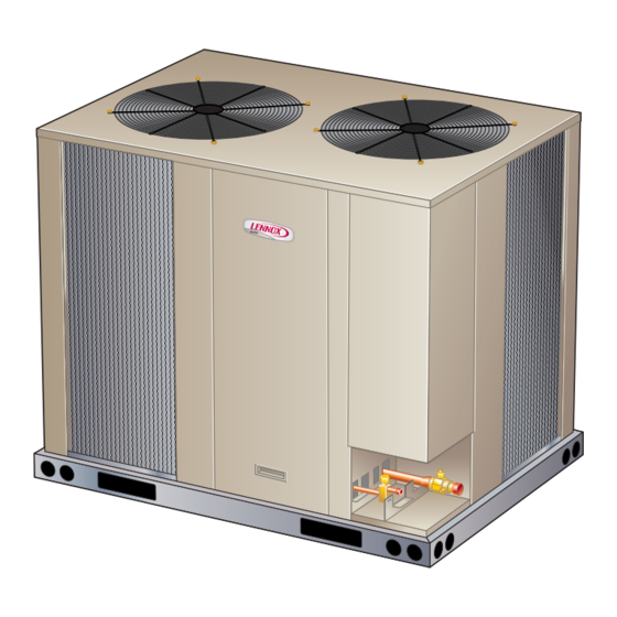
Outdoor Unit
ELP Series heat pumps, which will also be referred to in
this instruction as the outdoor unit, uses HFC-410A refrig-
erant. This outdoor unit must be installed with a matching
indoor unit and line set as outlined in the EL Series Engi-
neering Handbook.
This outdoor unit is designed for use in thermal expansion
valve (TXV) systems only.
Page 1
ELP Series
Advertisement
Table of Contents

Related Manuals for Lennox ELP090S4S


Summary of Contents for Lennox ELP090S4S
-
Page 1: Table Of Contents
INSTALLATION INSTRUCTIONS Elite Class ELP Series ™ 7.5 and 10 Ton HEAT PUMPS 7.5 AND 10 TONS 507744-01 11/2017 Table of Contents THIS MANUAL MUST BE LEFT WITH THE Shipping and Packing List ..........1 BUILDING OWNER FOR FUTURE REFERENCE Outdoor Unit ..............1 Unit Dimensions, Corner Weights and Centers of Gravity .2 WARNING Unit Plumbing Parts Arrangement ........3... -
Page 2: Unit Dimensions, Corner Weights And Centers Of Gravity
Corner Weights Centers of Gravity Model No. Model No. lbs. lbs. lbs. lbs. inch inch 21.80 29.0 ELP090S4S ELP090S4S 20.0 25.30 ELP120S4S ELP120S4S OPTIONAL HAIL GUARD (Field Installed All Coil Sides) (Not used with Coil Guard) INLET AIR OUTDOOR FAN GUARDS 9−1/8... -
Page 3: Unit Plumbing Parts Arrangement
Unit Plumbing Parts Arrangement ELP090S4S REVERSING DEFROST SWITCH VALVE LOCATION (S6) HIGH PRESSURE SWITCH (S4) PRESSURE SWITCH (S192) CHECK EXPANSION VALVE (CTXV) CTXV SENSING BULB LOSS OF CHARGE SWITCH (S24) LIQUID LINE SUCTION LINE SERVICE VALVE BI-FLOW DRIER LIQUID LINE SERVICE VALVE... -
Page 4: Model Number Identification
090 = 7.5 Tons S = Single Circuit 120 = 10 Tons Refrigerant Type 4 = R-410A Cooling Efficiency S = Standard Efficiency Unit Control Box Components Arrangement ELP090S4S AND ELP120S4S DEFROST CONTROL BOARD TRANSFORMER (T1) TERMINAL STRIP CONTACTOR (TB14) -
Page 5: Installation Clearances
50 linear feet (15 m) with refrigerant line sizes as outlined in table 1 (excluding equivalent length of fittings). Size refrigerant lines greater than 50 linear feet (15m or greater) according to the Lennox Refrigerant Pip- ing Design and Fabrication Guidelines (Corp. 9351-L9) or latest version. -
Page 6: Typical Control Wiring
INSTALL THERMOSTAT CIRCUIT SIZING AND DISCONNECT SWITCH MAIN FUSE BOX/BREAKER PANEL DISCONNECT SWITCH THERMOSTAT 5 FEET (1.5M) Install room thermostat (ordered separately) on an inside wall approximately in the center of the conditioned area and 5 feet (1.5m) from the floor. It should not be installed on an outside wall or where it Refer to the unit nameplate for minimum circuit ampacity amperage can be affected by sunlight, drafts or vibrations. - Page 7 TYPICAL UNIT CONTROL WIRE CONNECTIONS WIRE RUN LENGTH AWG# INSULATION TYPE CONTROL BOX LESS THAN 100’ (30M) TEMPERATURE RATING MORE THAN 100’ (30M) 35°C MINIMUM CONTACTOR RUN CONTROL WIRES THROUGH RIGHT CUTOUT. ROUTE THROUGH RUN CONTROL WIRES THROUGH WIRE TIES. WIRE TIES TIGHTEN MAKE CONTROL WIRE CONNECTIONS USING FIELD...
- Page 8 DUAL SPEED COMPRESSOR ACCORDANCE WITH NATIONAL AND LOCAL CODES ELP-090,120-G,J,M,Y WITH 2 SPD DISCONNECT ALL POWER BEFORE SERVICING COMP PROTECTION SECTION A5 REV. 0 537912-02 2011 FIGURE 3. Typical Wiring Diagram – ELP090S4S and ELP120S4S (G, J, Y, M Voltages) Page 8...
-
Page 9: Refrigerant Charge
If line set is less than 25 feet, subtract this 2 - Charge the unit using the approach method in the amount from each circuit. Refer to Lennox Refrigerant approach method section. Piping Design and Fabrication Guidelines for more infor- mation. - Page 10 Temperature (ºF) Temperature (ºC) An approach temperature less than this value (+/-1) (+/-.05) indicates an overcharge. ELP090S4S / ELA090 A - Add or remove charge in increments. ELP120S4S / B - Allow system to stabilize at least 5 minutes each ELA120 time refrigerant is added or removed.
- Page 11 TABLE 6. HFC-410A Temperature (ºF) – Pressure (Psig) °F Psig °F Psig °F Psig °F Psig °F Psig °F Psig °F Psig °F Psig 100.8 137.1 178.5 231.6 290.8 365.0 545.6 445.9 102.9 139.6 181.6 235.3 295.1 370.0 451.8 552.3 105.0 142.2 184.3...
-
Page 12: System Operation
System Operation Defrost Control Board The outdoor unit and indoor blower cycle on demand from DEFROST CONTROL TIMING PINS the room thermostat. When the thermostat blower switch is in the ON position, the indoor blower operates contin- FIELD SELECT uously. TIMING PINS HIGH PRESSURE SWITCHES (S4 AND S7) TEST... -
Page 13: Maintenance
During a single thermostat cycle, the defrost control will Maintenance lock out the unit after the fifth time that the circuit is in- terrupted by any pressure switch that is wired to the con- At the beginning of each cooling season, the system trol board. - Page 14 Start-Up and Performance Checklist Job Name Job no. Date Job Location City State Installer City State Unit Model No. Serial No. Service Technician Nameplate Voltage Rated Load Ampacity Compressor Amperage: Maximum Fuse or Circuit Breaker Electrical Connections Tight? Indoor Filter clean? Supply Voltage (Unit Off) Indoor Blower RPM S.P.
Need help?
Do you have a question about the ELP090S4S and is the answer not in the manual?
Questions and answers