Advertisement
ZB3001 (45857)
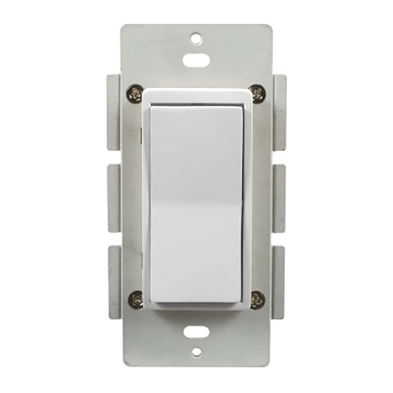
ZigBee®, In‐Wall On/Off/Dimmer Switch
Home Automation Standard Version 1.2 Compliant
Introduction
Thank you for your purchase of a Jasco ZigBee® control device. Jasco ZigBee lighting controls are
designed to automate lighting/home control and provide easy remote operation of all your ZigBee
enabled devices. The Jasco ZigBee product family includes a variety of devices to control lighting in your
home. It is up to you whether you want to control one room or your entire house and whether you want
to do it all now or start with one room and add more over time.
This dimmer switch is designed for use with permanently installed lighting fixtures only. The switch
has been optimized for use with incandescent lighting as well as with most dimmable CFL and LED
bulbs. The maximum load ratings for this switch are 600W for incandescent bulbs and 150W for
dimmable CFL and LED's. Lighting controlled by this switch must not exceed these stated limits.
NOTE: Actual performance of any CFL or LED will vary from bulb type to bulb type and among different
manufacturers. It is important to note that only bulbs that have been designed as dimmable should be used on a
dimmer. To find out if your bulb is dimmable, please check the package, the bulb itself,or call the bulb manufacturer
directly.
CAUTION ‐ To Reduce The Risk of Overheating and Possible Damage to Other Equipment, Do Not Install to
Control a Motor‐Operated Appliance, A Fluorescent Lighting Fixture or a Transformer Supplied Appliance
There are no user serviceable parts in this unit.
! Warning !
RISK OF FIRE
RISK OF ELECTRICAL SHOCK
RISK OF BURNS
NOT FOR USE WITH MEDICAL OR LIFE SUPPORT EQUIPMENT
ZigBee enabled devices should never be used to supply power to or control the On/Off status of medical and/
or life support equipment!
WARNING:
Controlling Appliances:
Exercise extreme caution when using ZigBee devices to control appliances. Operation of the ZigBee device may
be in a different room than the controlled appliance, also an unintentional activation may occur if the wrong
button on the controller interface is pressed. ZigBee devices may automatically be powered on due to timed
event programming. Depending upon the appliance, these unattended or unintentional operations could possibly
result in a hazardous.
1. Do Not include ZigBee devices in Groups or Scenes if they control appliances.
2. Do Not use ZigBee devices to control electric heaters or any other appliances which may present a hazardous
condition due to unattended or unintentional or automatic power on control.
Advertisement
Table of Contents

Related Manuals for Jasco ZigBee ZB3001 (45857)


Summary of Contents for Jasco ZigBee ZB3001 (45857)
- Page 1 ZB3001 (45857) ZigBee®, In‐Wall On/Off/Dimmer Switch Home Automation Standard Version 1.2 Compliant Introduction Thank you for your purchase of a Jasco ZigBee® control device. Jasco ZigBee lighting controls are designed to automate lighting/home control and provide easy remote operation of all your ZigBee enabled devices. The Jasco ZigBee product family includes a variety of devices to control lighting in your home. It is up to you whether you want to control one room or your entire house and whether you want to do it all now or start with one room and add more over time. This dimmer switch is designed for use with permanently installed lighting fixtures only. The switch has been optimized for use with incandescent lighting as well as with most dimmable CFL and LED bulbs. The maximum load ratings for this switch are 600W for incandescent bulbs and 150W for dimmable CFL and LED’s. Lighting controlled by this switch must not exceed these stated limits. NOTE: Actual performance of any CFL or LED will vary from bulb type to bulb type and among different manufacturers. It is important to note that only bulbs that have been designed as dimmable should be used on a dimmer. To find out if your bulb is dimmable, please check the package, the bulb itself,or call the bulb manufacturer directly. CAUTION ‐ To Reduce The Risk of Overheating and Possible Damage to Other Equipment, Do Not Install to Control a Motor‐Operated Appliance, A Fluorescent Lighting Fixture or a Transformer Supplied Appliance There are no user serviceable parts in this unit. ! Warning ! RISK OF FIRE RISK OF ELECTRICAL SHOCK RISK OF BURNS NOT FOR USE WITH MEDICAL OR LIFE SUPPORT EQUIPMENT ZigBee enabled devices should never be used to supply power to or control the On/Off status of medical and/ or life support equipment! WARNING: ...
-
Page 2: Key Features
Key Features Turn ON/OFF or DIM lighting manually or remotely via the ZigBee controller Can be Included in multiple Groups and Scenes May be used in single pole installation or with up to two Jasco auxiliary switches in 2‐way, 3‐ way or 4‐way wiring configurations Works with Dimmable CFL/LED bulbs for improved energy efficiency Interchangeable Paddle switch: White & light almond paddle in package Over the Air updates – Once joined to your ZigBee network, the device can transparently receive updates through your ZigBee gateway Energy Monitoring – The device can report wattage (W) and kilowatt hours (kWh). Energy usage is monitored through the ZigBee Controller Interface Uses a standard, decora‐size wall plate for single gang installations (wall plate not included) Blue LED indicates switch location in a dark room (LED can be enabled/disabled manually) LED Status Indicator – Indicates device scanning during pairing process ZigBee HA 1.2 Certified for simple pairing and integrated home automation Screw Terminal installation; requires wiring connections for Line (Hot), Load, Neutral, and Ground. Traveler wire required for multi pole installation To change color of the switch 1. Lift the Air Gap tab at the base of the cover. 2. Push side tabs in on one side and then the other to release cover. Lift the cover up and off. 3. Simply put the new cover onto the switch by inserting the air gap and side tabs and snapping securely into place. ... - Page 3 CONNECTIONS TWO‐WAY CONTROL THREE‐WAY CONTROL SINGLE SWITCH WIRING USING ONE PRIMARY TWO SWITCH WIRING USING ONE PRIMARY SWITCH AND ONE AUXILIARY SWITCH FOUR‐WAY CONTROL THREE SWITCH WIRING USING ONE PRIMARY AND TWO AUXILIARY SWITCHES Single, Dual and Triple Gang Boxes The metal plate surrounding the switch assembly is a heat sink. The maximum load rating (600W) is provided when installed in a single gang box with the full heat sink. Multiple dimmer switches may be installed in dual or triple gang boxes and, if necessary, one or both sides of the heat sink may be removed by bending it at the score lines.
- Page 4 CFL/LED RATING Incandescent RATING Number of Dimmers Heat Sink 150W 600W 1 Switch in Single Gang Full – No tabs removed Box 500W 125W 2 Switches in Double One tab removed Gang Box (Inner) 400W 100W 3 Switches in Triple Both tabs removed Gang Box Observe Important Wiring Information Important: This switch is rated for and intended to only be used with copper wire. The home’s electrical wires may be attached to the screw terminals or inserted into the holes in the back of the switch enclosure and clamped in place by tightening the screw terminals. Always follow the recommended wire strip lengths when making wiring connections. Wire gauge requirements • Use 14 AWG or larger wires suitable for at least 80° C for supply (HOT), Load, Neutral, Ground and Traveler connections. Wire strip length: • For attachment to screw terminals: Strip insulation 1 in (25mm) • For attachment using the enclosure’s holes: Strip insulation 5/8” (16mm) UL specifies that the tightening torque for the screws is 14 Kgf‐cm (12 lbf‐in). SINGLE SWITCH WIRING 1. Shut off power to the circuit at fuse box or circuit breaker. 2. Remove wall plate. ! Warning: Verify power is OFF to switch box before continuing. ...
-
Page 5: Basic Operation
10. Connect the white wire to the neutral terminal. Note: UL specifies that the tightening torque for the screws is 14 Kgf‐cm (12 lbf‐in). 11. Insert Switch into the switch box being careful not to pinch or crush wires. 12. Secure the switch to the box using the supplied screws. 13. Mount the wall plate. 14. Reapply power to the circuit at fuse box or circuit breaker and test the system. OPTIONAL for THREE or FOUR‐WAY CONTROL: Connect the Traveler wire (usually Red) to the screw terminal marked TRAVELER on the primary switch (Do Not remove the tape over the terminal if you are not using the traveler connection).The other end of this Traveler wire connects to the TRAVELER screw terminal on the Auxiliary Switch. 1. The auxiliary requires the following 3 wiring connections: a. The Traveler wire. This is used to send voltage signals to the primary switch. The signals from the auxiliary tell the primary switch what action to perform. b. Ground. c. Neutral. 2. DO NOT connect the auxiliary switch to the home’s black Hot (Line) wire. Once the switch is properly wired, you should be able to use the rocker to manually turn On/Off and dim the connected load Basic Operation The connected light can be turned ON/OFF in two ways: 1. Manually from the front panel of the in‐wall switch 2. Remotely with a ZigBee Controller MANUAL CONTROL The Front Panel Rocker Switch allows the user to: Turn ON/OFF the connected lighting. • To turn the connected lighting ON: Tap the top of the rocker. • To turn the connected lighting OFF: Tap the bottom of the rocker. To BRIGHTEN/DIM the connected lighting • To brighten the connected lighting, press and hold the top of the rocker until the desired ... -
Page 6: Remote Control
REMOTE CONTROL ZigBee devices can be controlled directly by your ZigBee Controller and remotely over long distances with a PC or mobile phone app if your home’s controller functions as a gateway connected to an internet router. To control the device remotely it must be paired to the ZigBee Controller as instructed ZigBee Network Pairing Join the switch to the ZigBee Network 1. From your ZigBee Controller’s interface, choose to add lighting device and enter Locating/Pairing mode as instructed by the controller. 2. After applying power to the In‐Wall switch, your In‐Wall Switch will begin auto scan mode as it searches for a controller to pair with Auto‐Scan: LED Status Indicator Blinks 3x every 10 seconds as the device scans for a compatible network controller to pair with until Timeout. Timeout: Auto‐Scan mode will eventually time out after the LED Status light stops blinking. If device Timeout occurs before the switch has joined the ZigBee network, press any button on the switch to resume scanning. 3. After the switch is located and paired to the ZigBee network, the LED Status Indicator will stop blinking and the switch will appear in your controller’s menu. Setup the switch as an On/Off control and title the switch in a way that will be easy to identify. The module is now paired to the ZigBee network and can be controlled remotely. Reset Device (Remove from ZigBee Network) From the ZigBee Controller From your controller or hub interface, choose to remove or delete the lighting device as instructed. The device will be removed from the ZigBee network following indication from your controller. All configuration parameters will be reset after the device is removed from the network. Manual Resetting to factory defaults require the user to: 1. Lift the air‐gap switch at the bottom of the rocker to OFF position to power down the device. 2. Hold down the UP button 3. Push In the air‐gap switch to ON position to power up the device. 4. Release UP button within 4 seconds after power up. -
Page 7: Led Parameters
LED Parameters To assist with locating the switch in a dark room, the LED glows blue when the light switch is turned OFF. To turn LED off: Tap top rocker (ON Switch) 3x quickly and then tap bottom rocker (OFF Switch) 1x To restore LED: Use the same series of button presses used to disable the LED to restore WARRANTY JASCO Products warrants this product to be free from manufacturing defects for a period of two years from the original date of consumer purchase. This warranty is limited to the repair or replacement of this product only and does not extend to consequential or incidental damage to other products that may be used with this product. This warranty is in lieu of all other warranties, expressed or implied. Some states do not allow limitations on how long an implied warranty lasts or permit the exclusion or limitation of incidental or consequential damage, so the above limitations may not apply to you. This warranty gives you specific rights, and you may also have other rights which vary from state to state. Please contact Customer Service at 800‐654‐8483 (option 1) between 7:30AM – 5:00PM CST or via our website (www.jascoproducts.com) if the unit should prove defective within the warranty period. FCC and IC Compliance U2ZZB3001 The Federal Communication Commission Radio Frequency Interference Statement includes the following paragraph: The equipment has been tested and found to comply with the limits for a Class B Digital Device, pursuant to part 15 of the FCC Rules. These limits are designed to provide reasonable protection against harmful interference in a residential installation. This equipment uses, generates, and can radiate radio frequency energy and, if not installed and used in accordance with the instruction, may cause harmful interference to radio communication. However, there is no guarantee that interference will not occur in a particular installation. If this equipment does cause harmful interference to radio or television reception, which can be determined by turning the equipment off and on, the user is encouraged to try to correct the interference by one or more of the following measures: Reorient or relocate the receiving antenna Increase the separation between the equipment and receiver Connect the equipment into an outlet on a circuit different from that to which the receiver is connected Consult the dealer or an experienced radio/TV technician for help Operation is subject to the following two conditions: This device may not cause interference ... -
Page 8: Operating Specifications
This device must not be co-located or operating in conjunction with any other antenna or transmitter. Compliance with IC Rules and Regulations IC: 6924A‐ZB3001 Jasco Products Company Model: ZB3001 (45857) CAN ICES‐3(B) / NMB‐3(B) This device complies with Industry Canada licence-exempt RSS standard(s). Operation is subject to the following two conditions: (1) this device may not cause interference, and (2) this device must accept any interference, including interference that may cause undesired operation of the device. - Page 9 LED Feit PAR20/LEDG5 9.5W LED Utilitech LPAR20/LEDG5 9.5W CFL Ecosmart 40114 (SKU#709447) 14W LED Philips 3.5E26BA12DBBAAA 3.5W LED Miseengarde LED7P20DS827/20 7W CFL Utilitech LPAR20DM/LED(338804) 7.5W LED Philips 9E26PA19DCAAAA 8W JASCO Products 10 E. Memorial Rd Oklahoma City, OK 73114 www.jascoproducts.com ZigBee® is a registered US trademark of the ZigBee Alliance The images, product information and specifications listed in this document are preliminary and subject to change ...
Need help?
Do you have a question about the ZigBee ZB3001 (45857) and is the answer not in the manual?
Questions and answers