
Related Manuals for Reo Elektronik REOTRON MDW 700


Summary of Contents for Reo Elektronik REOTRON MDW 700
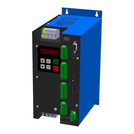
- Page 1 REOTRON Electronic Power Controller MDW 700 3-Phase-Thyristor Power Controller MDW_700_EN_ANL_34-13.doc 21.08.2013...
-
Page 2: Table Of Contents
REOTRON MDW 700 Operating instructions Contents Technical Information for the User ....................... 2 1.0 General ..............................3 2.0 Construction ............................3 3.0 Functions ..............................4 3.1 Modes ..............................4 3.2 Regulation mode ..........................5 3.3 Set point .............................. 5 3.4 Feedback ............................6 3.5 Control functions .......................... -
Page 3: Technical Information For The User
REOTRON MDW 700 Operating instructions Technical Information for the User This description contains the necessary information for the correct application of the product described below. It is intended for use by technically qualified personal. Qualified personnel are persons who, because of their training, experience and position as well as their... -
Page 4: General
REOTRON MDW 700 Operating instructions 1.0 General The range of REOTRON MDW Thyristor Regulators are microprocessor based units for controlling the power to resistive and inductive loads. In essence the units comprise inverse parallel connected power semiconductors (thyristors) and the control and regulation electronics. The units have a regulated, AC output. -
Page 5: Functions
REOTRON MDW 700 Operating instructions 3.0 Functions Features: Mode: 1. Phase angle control 2. Full wave principle Regulation mode: 1. Current regulation 2. Voltage regulation 3. Power regulation Real power Set point inputs: 1. Voltage or Power Potentiometer 10 kR, 0...+10 V, 0(4)...20 mA, internal Keypad 2. -
Page 6: Regulation Mode
REOTRON MDW 700 Operating instructions 3.2 Regulation mode The REOTRON MDW Thyristor Regulator range include 3 regulators, ie. voltage, current and power regulator. All the regulators always work in combination, ie. with voltage regulation for example, the cur- rent regulation operates like a cascade control and limits the output current in case of overload on the rated current. -
Page 7: Feedback
REOTRON MDW 700 Operating instructions 3.4 Feedback Current feedback The current is measured, in one phase, with an internal current transformer. The internal microprocessor determines the effective value of the output current and makes adjustments through a PI loop. Voltage feedback The effective voltage is measured with an internal Transformer. -
Page 8: Technical Data
REOTRON MDW 700 Operating instructions Failure relay (clamp 44, 45, 46) In case of an error (for example “Error Hot”) the contact 45 – 46 closes. Clamp assignment: normally close (NC) change-over contact (CO) normally open (NO) 4.0 Technical Data... -
Page 9: Ordering Codes
Input voltage Output current ID.-No.: REOTRON MDW 700-10/230 – 400 6401.01 230 – 400 3x 10 REOTRON MDW 700-10/230 – 400 Profibus DP 6401.10 230 – 400 3x 10 REOTRON MDW 700-10/230 – 400 RS-232 6401.30 230 – 400 3x 10 REOTRON MDW 700-25/230 –... -
Page 10: Operation
REOTRON MDW 700 Operating instructions 7.0 Operation The six buttons and a LED display found in the front panel, are used for operating and setting up the unit. All operating DISPLAY methods and adjustable parameters can be set up through this panel. -
Page 11: Indications On Display
REOTRON MDW 700 Operating instructions 7.3 Indications on display During normal running mode ‘run’ is shown in the LED display. In the programming mode an abbreviation for the corresponding parameter (see setting up instructions) and the setting values, are displayed. Setting changes are stored upon leaving the programming mode or after a pause of 100 seconds. -
Page 12: Settings
REOTRON MDW 700 Operating instructions 8.0 Settings The following table contains all the available key settable parameters. The unit is supplied with factory settings that can be recalled from access code “C210” under FAC. User codes can be saved under code “C143” and then recalled with code “C210” under USPA. -
Page 13: Setting Up Instructions
REOTRON MDW 700 Operating instructions 9.0 Setting up instructions 9.1 Internal set point Code C 002 Set point 1, Voltage [%] Set point 2, Current [%] Set point 3, Power [%] Running mode 9.2 Unit configuration Code 003 E.S.O. = 0 = External Set point E.S.O. -
Page 14: Service Menu
REOTRON MDW 700 Operating instructions 9.2.1 Service menu Display set-points sent to the unit. Code 050 Display set point voltage [%] Display set point current [%] Display set point power [%] Running mode 9.2.2 Display effective values measured inside unit... -
Page 15: Setting Up Procedures
REOTRON MDW 700 Operating instructions 9.3 Setting Up Procedures Code 020 Min ouptput voltage [%] (without external set point) Min output current [%] (without external set point) Min output power [%] (without external set point) Output voltage limit [%] Umax... -
Page 16: Save Current Settings
REOTRON MDW 700 Operating instructions 9.5 Save current settings Code C 143 Save current parameter settings Running mode 9.6 Restore parameter settings Code C 210 Restore factory settings Restore user settings (previously saved in "C 143" Running mode 9.7 Software version... -
Page 17: Connection Diagram
REOTRON MDW 700 Operating instructions 10.0 Connection diagram... -
Page 18: Connection Details
REOTRON MDW 700 Operating instructions 10.1 Connection details 41 42 43 44 45 46 13 14 15 16 17 18... -
Page 19: Dimensions
REOTRON MDW 700 Operating instructions 11.0 Dimensions MDW 700 10 A / 25 A Option 5 mm 9 mm PE L1 L2 L3 PROFIBUS DISCONNECT POWER INPUT BEFORE REPLACING FUSE ADR. FOR CONTINUED FIRE PROTECTION REPLACE ONLY WITH SPECIFIED TYPE AND RATED FUSE... - Page 20 REOTRON MDW 700 Operating instructions MDW 700 110A / 150A / 200A Attention connect the fan! Ø6 230V Ø8,5 PROFIBUS DISCONNECT POWER INPUT BEFORE REPLACING FUSE ADR. FOR CONTINUED FIRE PROTECTION REPLACE ONLY WITH SPECIFIED TYPE AND RATED FUSE DO NOT USE...
- Page 21 REOTRON MDW 700 Operating instructions MDW 700 300A Attention connect the fan! Input air cooling Input air cooling Ø8,5 DP 24 PROFIBUS ADR. RESET 24V DC REOTRON www.reo.de Input 230V 50/60Hz Ø8,5 Ø5,0 Output air cooling...
- Page 22 REOTRON MDW 700 Operating instructions MDW 700 WK (water-cooled) Ø 9,0 Ø 19,0 DP 24 PROFIBUS ADR. RESET 24V DC REOTRON www.reo.de Ø 9,0 Type MDW - WK 115, 160, 250, 350 MDW - WK 450, 600...
-
Page 23: Putting Into Service
REOTRON MDW 700 Operating instructions 12.0 Putting into service Safety Instruction Qualified personnel only, are permitted to install electronic equipment Because attenuation capacitors (Y-capacitors) are used, leakage current flows through the case to pro- tective earth (PE). Therefore, units must be earthed. -
Page 24: Installation Of Thyristor Control Units
REOTRON MDW 700 Operating instructions 13.0 Installation of Thyristor Control Units 13.1 Fuses The REOTRON MDW... series of thyristor controllers are fitted with semiconductor fuses, which protect the power semiconductors (thyristors) from damage when there is a short-circuit on the output. These fuses are selected for the permitted peak current of the semiconductors and are not provided for protec- tion against overload or line faults! Fuses are provided only in the current-carrying circuits with thyristors. -
Page 25: Interference Prevention
REOTRON MDW 700 Operating instructions 14.0 Interference prevention 14.1 Earthing Correct earthing of electronic controls is highly important for two reasons: First it ensures the safety of operators and service personnel, and secondly it provides a fail-safe opera- tion of the equipment. Therefore, in addition to providing protective earthing, in accordance to DIN stand- ards, it also provides an earth path for pulse interference produced during operation. -
Page 26: Engineering Notes
REOTRON MDW 700 Operating instructions 15.0 Engineering notes Type connection terminal connection terminal (power) (control) REOTRON MDW 700-10 4 mm 1,5 mm REOTRON MDW 700-25 4 mm 1,5 mm REOTRON MDW 700-50 16 mm 1,5 mm REOTRON MDW 700-80 35 mm... - Page 27 REOTRON MDW 700 Operating instructions...
- Page 28 Headquarters - German y REO ELEKTRONIK AG Brühler Straße 100 · D -42657 Solingen Tel.: +49 (0)212 8804 0 · Fax: +49 (0)212 8804 188 REO INDUCTIVE COMPONENTS AG Brühler Straße 100 · D -42657 Solingen Tel.: +49 (0)212 8804 0 · Fax: +49 (0)212 8804 188 E-Mail: info@reo.de...
Need help?
Do you have a question about the REOTRON MDW 700 and is the answer not in the manual?
Questions and answers