
Related Manuals for Yoko Technology RYK-IPBX100

Summary of Contents for Yoko Technology RYK-IPBX100
- Page 1 Full HD/RealTime D&N Auto-Iris Indoor & Outdoor Box IP Camera User’s Manual - 1 - 2013/09/03 version 1.1...
- Page 2 CAUTION RISK OF ELECTRIC SHOCK. DO NOT OPEN! CAUTION : TO REDUCE THE RISK OF ELECTRICAL SHOCK, DO NOT OPEN COVERS (OR BACK). NO USER SERVICEABLE PARTS INSIDE. REFER SERVICING TO QUALIFIED SERVICE PERSONNEL. It is advised to read the Safety Precaution Guide through carefully before operating the product, prevent any possible danger.
-
Page 3: Table Of Contents
Table of Contents Product Feature ________________________________________________________________ - 5 - Package Contents ______________________________________________________________ - 6 - Physical Description _____________________________________________________________ - 6 - Quick Installation _______________________________________________________________ - 9 - Software Installation ___________________________________________________________ - 14 - CHAPTER 1. System Configuration ________________________________________________ - 17 - User Login ________________________________________________________________ - 17 - CHAPTER 2. - Page 4 Appendix A – Product FAQ ______________________________________________________ - 67 - A. Web snapshot and recording doesn’t work in windows 7? ______________________________ - 67 - B. After login camera, image page shows “connecting” message without showing image instead? - 67 - C. Unable to see image because of ActiveX unsuccessful installation ________________________ - 68 - D.
-
Page 5: Product Feature
Product Feature 2 Megapixel image; resolution is up 1920x1080 (3 Megapixel model resolution can reach 2048x1536). Support True WDR image processing. (For 3 Megapixel model) Support H.264 / MJPEG codec, video quality is adjustable, video type can be divided into Profile 1、Profile 2. -
Page 6: Package Contents
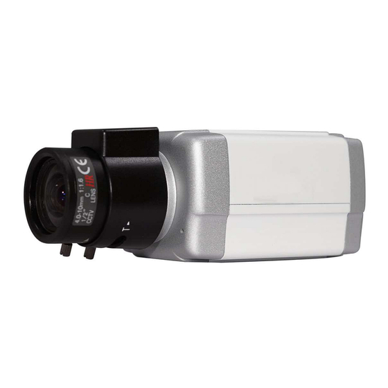
Package Contents IP Camera Quick Guide Installation CD Power Adaptor Ethernet Cable Accessory Pack 2Pin Connector 4Pin Connector Physical Description Front/Rear Panel Description Lens Auto IRIS vari-focal lens is recommended to go with the camera. To fit in different lens, please adjust the ring screw accordingly to set correct focus. - Page 7 RESET When system is frozen, please press the reset button and keep it depressed for 5 seconds, after the power light is blinking, then release the reset button, the system will finish rebooting procedure in one minute. When the power light is on; the device is booted up successfully. Power Lighting When power lighting on means device boots up successfully;...
- Page 8 Micro SD Support Micro SD card, the maximal capacity could be up to 32 GB. Device doesn’t support Micro SD hot swapping, please reboot system after insert or remove Micro SD card. 12V DC/1A Power Connector Connect to 12V DC power adapter. Video Out Slot for video out connector.
-
Page 9: Quick Installation
Quick Installation Bracket Installation Basic Connection (1) Connect the 12V DC adaptor to the power jack of the IP camera. (2) Use Ethernet cable to make connection from the Ethernet 10/100 RJ45 socket of IP camera to the PC. - 9 - 2013/09/03 version 1.1... -
Page 10: Network Setting
Network Setting After completing the basic hardware connection, make sure that the PC and the IP camera IP address are both in the same network segment. Example: Setup preset IP camera IP to 192.168.100.100 and configure your PC IP address as the figure description below. Setup format:... - Page 11 (4) Choose which device you would like to access, the default IP address on the device is 192.168.100.100 (5) Double click on the IP address, will automatically open the selected device web image. (6) Please select on the device you would like to modify its setting and click “Modify”. Please fill in username and password.
- Page 12 192.168.100.100 in LAN, system will automatically assign an IP address of which is the same network segment as client PC. To enable this function, please “Enable” on Auto Assign IP item. Please notice that DO NOT enable this function when there is already a DHCP server in LAN in case of IP conflict issues.
- Page 13 (3) Once Active X installation complete, you will see the live viewing page. - 13 - 2013/09/03 version 1.1...
-
Page 14: Software Installation
Software Installation Please install following software from installation CD. Install Utility (1) Click Install Utility Tool (2) Click Next. - 14 - 2013/09/03 version 1.1... - Page 15 (3) Select Installation Folder. (4) Confirm Installation, please click Next. - 15 - 2013/09/03 version 1.1...
- Page 16 (5) Installation complete, please click Close to exit. Recommended Computer Equipment Intel® Core 2 Due E7200 or above 1GB or above Audio Card Needed Windows 2000, Windows XP SP2 and Operation System above, Windows Vista, Windows 7 Browser IE6 SP2 and above - 16 - 2013/09/03 version 1.1...
-
Page 17: Chapter 1. System Configuration
CHAPTER 1. System Configuration 1.1 User Login One minute after the device is powered on, please start Utility. The program will automatically search and display supportive devices in local LAN. Please click on the device you would like to access, and then enter login page of the device. Login device with default username and password: admin / admin. -
Page 18: Chapter 2. Live View Page
CHAPTER 2. Live View Page 2.1 Video Type Video type can be divided into Profile 1、Profile 2. ※ ※ ※ ※ NOTE: Every single profile can be configured the video stream compression, resolution, frame rate, and bitrate. 2.2 Protocol Type Select image streaming transmission protocol. -
Page 19: Utility
RTSP/ UDP Choose this item to get smooth live streaming. Video and audio streaming transmits through network UDP layer. ※ ※ ※ ※ NOTE: (1) When the network environment is not in LAN, please choose RTSP/TCP protocol type to obtain image. (2) RTSP / UDP protocol is not applicable for different network segments. - Page 20 Recording Click on the button to start recording. Record file will be stored in default path. Regarding the default path, please see chapter3.1 (Client setting). Recording file is cut every 5 minutes; when the remaining space is less than 1GB or system setting is changed, recording will automatically stop.
-
Page 21: Light Status
(1) Direction Control Control the angles and direction of camera, with up, down, left, right, up left, up right, down left, and down right. Press a direction button; camera will rotate in this direction until releasing the button. The middle button is for back to home. 2.4 Light Status The lights from left to right are recording, audio and broadcast function status. -
Page 22: Chapter 3. Client Setting
CHAPTER 3. Client Setting 3.1 Default Path Recording Select to change saving path of web recording files. Default is at “My Documents/(MAC address)”. Snapshot Select to change saving path of web snapshot files. Default is at “My Documents/(MAC address)”. Prefix Configuring prefix file name of the video files. -
Page 23: Sound
Date style: (prefix file name)(yyyy)-(mm)-(dd)-(five random number). Time style: (prefix file name)(yyyy)-(mm)-(dd)-(hh)-(mm)-(ss)-(four random number). 3.2 Sound Sound Recording Enable audio function while recording. 3.3 Real Time OSD Setting Display Items Select frame rate on video: frame rate per sec displayed on video image. Color Select OSD font color: White, Black, Red, Green, Blue, Yellow, Cyan, and Magenta Position... -
Page 24: Chapter 4. Web Setting
CHAPTER 4. Web Setting Click on Setting” on the top right corner of the web page to configure the device, click on “LiveView” to return back to live view image. Setup - 24 - 2013/09/03 version 1.1... -
Page 25: System Setting
4.1 System Setting 4.1.1. Information This page will display the device status information, string field displayed information includes the configuration of the system, Ethernet, PPPoE, WebPort, DDNS. - 25 - 2013/09/03 version 1.1... -
Page 26: Advanced Setting
4.1.2. Advanced Setting System Setting Firmware Upgrade To perform firmware upgrade, click on firmware upgrade button. Choose new firmware file, *.img, and click “Upgrade” button. System will automatically perform firmware upgrade. The whole process may take about 5 minutes to complete. DO NOT power off device during firmware upgrade in case system malfunction occur. -
Page 27: Time Setting
※ ※ ※ ※ NOTE:Download the profiles, by the "Network" or "Daylight Saving Time" option to select in the configuration file download, the server-side to retain the settings, do not download with configure profiles. Configuration Upgrade Click on the Upgrade button, you can upload a profile update existing equipment setting. 4.1.3. - Page 28 Automatic ◎ NTP Server Fill in NTP server address. User can choose any one of below public NTP servers to use. time.stdtime.gov.tw asia.pool.ntp.org tw.pool.ntp.org us.pool.ntp.org europe.pool.ntp.org oceania.pool.ntp.org south-america.pool.ntp.org ◎ Updating interval Enable to synchronize time with NTP server every hour. 4.1.4.
- Page 29 End Time Fill in the end time of DST, the format should be: mm/dd. 4.1.5. Log Log is the complete operation record of IP camera. If any trouble of IP camera, users can review and check it to find the failure root cause. Remote Log Enable remote log, all the log file can be saved in log server by internet.
-
Page 30: Network Setting
4.2 Network Setting 4.2.1. Basic DHCP Click on enable to activate DHCP; the device will get IP address from DHCP server. Static IP Manually set the IP address for the device. ◎ IP Address Fill in IP address for the device ◎... - Page 31 PPPoE Connect the device to internet by PPPoE through ISP. User Name Fill in the user name of the ISP account. Password Fill the password of the ISP account. Authentication Select the ISP PPPoE connection authentication, RAP or CHAP,before PPPoE connection. ※...
- Page 32 4.2.3. Service DDNS Setting DDNS Enable this item to activate DDNS function. Server Select DDNS service system: dyndns.org or dhs.org, please access the DDNS websites below to apply for DDNS service. http://www.dyndns.com http://www.dhs.org Host Name Host name that user register for the device in DDNS website. User Name Username that user register in DDNS website.
- Page 33 UPnP Setting Define the host name name. Enable this function to open UPnP service. Device can be found in “My network places 4.2.4. HTTP Web Port Setup device web port number, default is 80. To change to another port number, take 8080 for instance, set hyperlink format as below: http://192.168.100.100:8080 Do not duplicate web port with advanced ports.
-
Page 34: Ip Address Filter
Create and install certificate method Create and install SSL certification in IP camera when HTTPS activate, two methods for options: Create self-signed certificate manually Create certificate request and install 4.2.5. IP Address Filter - 34 - 2013/09/03 version 1.1... - Page 35 IP Filter Setting Filter IP addresses and select to receive or refuse requirements from IP IP Filter Type allow : Allow all the IP addresses connect to the device IP Filter Type deny : Deny all the IP addresses connect to the device, at least reserve 1set IP address to enable the function.
-
Page 36: Wireless Setting
4.2.6. Wireless Setting The IP camera can connect to internet by wireless USB adapter (support 2.4G 802.11.b/g/n). ※ ※ ※ ※ NOTE: IP camera cannot connect to internet by 5G band wireless USB adapter and AP. WLAN Enable wireless network Wireless List IP camera will list out available wireless AP automatically. - Page 37 Network Mode BSS network modes: Ad-Hoc and Infrastructure. Signal Strength Signal strength of wireless AP, value is from 1 to 100. The higher value, the stronger signal; and vice versa. Wireless Standard Wireless standard of AP can support up to 802.11 b/g/n. Security Mode Security mode of AP, OPEN、SHARED、WPA-PSK、WPA2-PSK mode.
- Page 38 ◎ IP Address Configure IP address of USB adapter. ◎ Subnet Mask Configure subnet mask of USB adapter. ◎ Gateway Configure gateway of USB adapter. (Normally configure IP address of AP). ◎ Primary DNS Configure primary DNS of USB adapter. ◎...
-
Page 39: Camera
4.3 Camera 4.3.1. Basic Video Setting Video streaming is defined by profile 1 and 2,two streaming. Stream profile name: Configure every streaming name, which will be displayed on video type in Web UI for selections. Compression: Configure video compression, H.264 and MJPEG. Resolution: For configuring video resolution, the higher the resolution, the better image quality, the bigger image size, the available resolution listed as below... - Page 40 1280 x 720 1280 x 960 1280 x 1024 1920 x 1080 2048 x 1536 This resolution is only supported 3 megapixel model ※ ※ ※ ※ NOTE: Note: Stream 2 is fixed by default up to resolution720x480 for better video quality.
- Page 41 Audio Mode Settings Duplex Mode : Select full duplex or half duplex mode, it’s full duplex by default. Please select duplex mode depending on the environment. Half duplex mode can be configured to avoid echo occurs; however, it cannot support two way audio simultaneously, it only can be one way audio prior to the other way audio.
- Page 42 Video Out Settings Enable video output Video output through BNC connector of IP camera to displayer Video output type Select the video display mode for NTSC or PAL format ◎ HW : According to the hardware switch to adjust the video output for NTSC or PAL format.
- Page 43 4.3.2. Image Basic Setting - 43 - 2013/09/03 version 1.1...
- Page 44 Image Color Select image color in color or mono. Brightness Adjust image brightness parameter; the higher the value, the brighter the image. Saturation Adjust image saturation parameter; the higher the value, the more saturate the image. Contrast Adjust image contrast parameter; the higher the value, the higher the contrast of image. Adjust video hue parameter, the smaller the value, the bluer the video is;...
- Page 45 ※ ※ ※ ※ NOTE: Pictures for reference only, please select WDR level according to the environment. White Balance Choose Current White Balance Way; default setting is Auto White Balance。 ◎ AWB (Color Temperature 2800~6500K) ◎ ATW (Color Temperature 2500~8000K) ◎...
- Page 46 Day / Night Setting Day/ Night is set for controlling ICR switching, it’s auto by default. Day / Night ◎ Auto: ICR switch automatically depends on the illumination of scene difference. ICR switches to night mode, live image switches to mono color. ◎...
- Page 47 IRIS: select auto or manual ◎ Auto: Auto-iris can automatically adjust the amount of light entering with a mechanism to have a camera stay in an optimal light level. ◎ Fix Max: Iris fixed to the maximum. Shutter Speed : select auto or manual, shutter speed can be configured 1/4~1/10000, the higher speed, the less exposure, the darker video image;...
- Page 48 4.3.3. OSD (On Screen Display) Recording OSD Setting Display OSD on record files. Display Enable to display system date and time on recording OSD. Title Enter desired title and select Enable to display title on the recorded video image. Maximal word length is 16 characters. - 48 - 2013/09/03 version 1.1...
- Page 49 4.3.4. PA (Privacy Area) Video Private area setting in video image, left click to set the area range with 3 areas, each by red, green, and blue for identification. Delete Click the button to delete privacy of chosen rectangle color. Clear All Click the button to clear all privacy areas.
-
Page 50: Ptz
4.4 PTZ 4.4.1. Basic PTZ Setting IP cameras connect to cradle head by RS485. Configure the PTZ setting to control cradle head. (Please refer to user manual chapter 2.3 Utility PTZ button) Pan Speed Select the pan speed value, the bigger value, the higher speed; vice versa. Tilt Speed Select the tilt speed value, the bigger value, the higher speed;... -
Page 51: Motion Detection
4.5 Motion Detection 4.5.1. Basic Motion Detection Enable motion detection, the relate alarm notice will be automatically triggered when IP camera detect motion in the specifying area. Event trigger time can be configured at least 1 second. After event trigger relate actions completed, IP camera still detected motion, the event will be triggered repeatedly. - Page 52 Select All Click the button to enable full area detection. Delete Click the button to delete privacy of chosen rectangle color. Clear All Click the button to clear all privacy areas. Motion Detection Setting Status Enable this item to activate motion detection. Name Configure the name of 3 areas by each for identification.
-
Page 53: Event
4.6 Event 4.6.1. Basic IP camera provide three types event alarm: Motion detection、Periodically、Digital input. Through event setting, event trigger alarm can be delivered by SD card, email, and FTP. Event Setting ◎ Name : Display event name ◎ Status: Enable each event type status and will enable relate rigger actions. The function is the same as “enable this event”... - Page 54 ◎ Add : Select event type and add it in event trigger ◎ Delete : Select event type and delete event trigger Event Setting ◎ Event name : Configure event name with 40 bits maximum ◎ Enable this event : Enable relate event-trigger actions ◎...
-
Page 55: Digital Input
◎ Digital input: Enable digital output (connect IP camera digital in port ) to trigger alarm by selecting Open or close ※ ※ ※ ※ NOTE: Open stands for ground (G) and digital in (IN) is open, when they touch together, it will trigger message transmission to digital output;... - Page 56 Configure relate actions after event-trigger, such as alarm out, SD card storage, FTP & Email transmission. ◎ Trigger digital output : alarm device is connected to IP camera I/O N.O and COM connector, ex: buzzers. ◎ AlarmOut_1: Enable AlarmOut_1 by selecting normal open (NO) or normal close (NC) to enable alarm device.
- Page 57 E-mail Setting Email To : fill e-mail address (five mails addresses the maximum) Subject : fill in e-mail subject Message : E-mail content Server Setting Select alarm transmissions method, FTP or SMTP, when event trigger alarm. ◎ Name : Display Server name ◎...
- Page 58 Server Setting ◎ Server name : Fill in server name Server Type ◎ E-mail Sender email address : Fill in sender’s e-mail Address Server address : Fill SMTP Server address User name : Fill in sender’s email account Password: Fill in sender’s email password Server Port : Fill in SMTP Server Port, it is 25 by default.
- Page 59 ◎ Test Selected server type Enable the item for testing email successful transmission. Email To : Fill in receiver’s e-mail address Subject : Fill in e-mail subject Message : Fill in e-mail content ◎ FTP Sender address : Fill in FTP server address Server Port: Fill in FTP Server Port, it is 21 by default.
- Page 60 Media Setting Configure the media of alarm, IP camera provide event recording (pre-event and post-event) in current stage. ◎ Name : Display Media name ◎ Type : Display Media type,only pre-event and post-event recording (VideoClip) ◎ Add : Add Media function ◎...
-
Page 61: Recording
4.7 Recording 4.7.1. Basic Recording settings Configure it for recording video by schedule and network failure, which are both saved in SD card. ◎ Name : Display recording video name ◎ Status : Enable relate recording actions, the same function as “Enable this Recording” ◎... - Page 62 Trigger Recording video by schedule and network failure, the files will be saved in SD card. ◎ Schedule Recording video by schedule configuration, the files will be saved in SD card ◎ Network fail Recording video by network failure, IP camera will start recording from 5 seconds before network failure.
- Page 63 File Format ◎ Destination Display recording video storage destination, only saved in SD card ◎ Max File length Video recording file length, range from 1~6 minutes ◎ Folder Format Folder of video recording format, Recording Name or Date And Time. Recording Name : Folder is named the same as recording name.
-
Page 64: User Management
4.8 User Management 4.8.1 Basic Change Password Enter the original password and new password, click on “change” button to finish password change. Password of operator and guest accounts are not changeable, if user wants to change the password of operator and guest accounts, please login as administrator, and delete operator or guest account, and create new accounts. - Page 65 User List List all users in the table. Click on “Delete” button to delete user. User Security Level System provides three levels users; please refer to below table for each level’s permission. Live View Live View User User Level Broadcast Setting Image Utility...
-
Page 66: Storage Device
4.9 Storage Device 4.9.1. Basic SD card shall be formatted by FAT32 before installing SD card to avoid detection failure. Total Capacity Display the total capacity of the backup device. Used Capacity Display the used space of the backup device. Remaining Capacity Display free space of the backup device. -
Page 67: Appendix A - Product Faq
Appendix A – Product FAQ A. Web snapshot and recording doesn’t work in windows 7? Due to windows authority limitation, please use following procedure to fix this problem. Right click on “Internet Explorer” icon and choose “Run as administrator”. All operations on camera web page can work normally then. -
Page 68: Unable To See Image Because Of Activex Unsuccessful Installation
C. Unable to see image because of ActiveX unsuccessful installation 1. Disable memory protection of IE8, WinXP (1) Open an IE window and click “Tools”→”Internet Options”. (2) Click on “Advanced” tag and disable “Enable memory protection to help mitigate online attacks" option”. Click “Apply” to exit. - 68 - 2013/09/03 version 1.1... - Page 69 (3) Restart IE to affect setting. (4) Reconnect IP camera web page, ActiveX control plug-in is ready to install. 2. Disable IE protected mode of IE8, Win7 (1) Open an IE window and click “Tools”→”Internet Options”. (2) Click on “Security” tag, disable “Enable Protected Mode (requires restarting Internet Explorer)”.
- Page 70 (3) Click on “Advanced” tag and disable “Enable memory protection to help mitigate online attacks" option”. Click “Apply” to exit. (4) Restart IE to affect setting. (5) Reconnect IP camera web page, ActiveX control plug-in is ready to install. - 70 - 2013/09/03 version 1.1...
-
Page 71: Web Page Does Not Display Correctly After Firmware Upgrade
D. Web page does not display correctly after firmware upgrade. This problem may cause by temporary internet cache, please follow procedures to fix. (1) Open an IE window and click “Tools”→”Internet Options”. (2) Click “General” tag and click “Delete…” in browsing history field. - 71 - 2013/09/03 version 1.1... - Page 72 (3) Delete “Temporary Internet files” and “Cookies” both items. (4) Restart IE to affect setting. (5) Reconnect IP camera web page. - 72 - 2013/09/03 version 1.1...
-
Page 73: Unable To Open Camera Web Page But Utility Could Search Ip Camera Information Under Direct
E. Unable to open camera web page but Utility could search IP camera information under direct connection between PC and IP camera. This problem may cause by following reasons: 1. Does PC and IP camera set in the same network segment? Please refer to “Setup”... - Page 74 (3) Disable "Use a proxy server for your LAN", then click [OK] button. (4) Restart IE to affect setting. (5) Reconnect IP camera web page. ※ ※ ※ ※ To connect IP camera without through proxy server in LAN, please follow procedures: (1) Click “Advanced”.
- Page 75 (2) Fill in “192.168 .*.*” in exceptions, then click “OK” to exit. (3) Restart IE to affect seeting. (4) Reconnect IP camera web page - 75 - 2013/09/03 version 1.1...
-
Page 76: Appendix B - 3Gpp On Iphone
Appendix B – 3GPP on 3GPP on iPhone ※ IP cameras provide free bundled APP for live viewing free bundled APP for live viewing, the steps as follows: , the steps as follows: (3) Please click on the main the main screen (2) Click on "Search"... - Page 77 (5) Click on【 【 【 【 +】 】 】 】 button to add IP cameras (6) Configure IP address, port number (default 554), username, and password of IP camera and click on【 【 【 【 Save】 】 】 】 button - 77 - 2013/09/03 version 1.1...
- Page 78 (7) Click on the configured IP camera (8) Live view IP camera ※ ※ ※ ※ NOTE: APP captures the 2nd stream of IP camera. For more smooth video quality, the suggested configuration is that the resolution is 640x480, bitrate 1M, and frame rate 30fps. - 78 - 2013/09/03 version 1.1...
-
Page 79: Appendix C - 3Gpp On Android
Appendix C – 3GPP on Android ※ IP cameras provide free bundled APP for live viewing, the steps as follows: (1) Please click on the main screen (2) Click on "Search" icon and search for『 『 『 『 SecuCON Mobile』 。 』... - Page 80 (5) Click on【 【 【 【 +】 】 】 】 button to add IP cameras. (6) Configure IP address, port number (default 554), username, and password of IP camera and click on【 【 【 【 Save】 】 】 】 button. - 80 - 2013/09/03 version 1.1...
- Page 81 (7) Click on the configured IP camera. (8) Live view IP camera. ※ ※ ※ ※ NOTE: APP captures the 2nd stream of IP camera. For more smooth video quality, the suggested configuration is that the resolution is 640x480, bitrate 1M, and frame rate 30fps. - 81 - 2013/09/03 version 1.1...
-
Page 82: Appendix D - Specifications
Appendix D – Specifications Model No. RYK-IPBX100 RYK-IPBX200 RYK-IPBX300 1/2.7” Progressive 1/2.7” Progressive 1/2.8” SONY "Exmor" Sensor CMOS CMOS CMOS 1.3 Mega 2.0 Mega 3 Mega Resolution 1280 x 1024 1920 x 1080 2048 x 1536@20fps Picture Elements 30fps 1920 x 1080@30fps... - Page 83 IE, , Mobile Live Viewing Micro SD Card Slot SD Card Slot 1 x DI, 1 x DO(Dry Contact) Alarm RS485 DC 12V 1A/ PoE 802.3 AF Power 0 °C ~ 50 °C / 32 °F ~ 122 °F Operating Temp. CGI URL Command Integrate Document GENERAL...
Need help?
Do you have a question about the RYK-IPBX100 and is the answer not in the manual?
Questions and answers