Table of Contents
Advertisement
Quick Links
Advertisement
Table of Contents
Troubleshooting

Subscribe to Our Youtube Channel
Summary of Contents for MARKEM Cimjet RFID
- Page 1 Operation/Service Manual Cimjet RFID ® Cimjet RFID ® ® Operation/Service Manual...
- Page 3 WARRANTIES OF MERCHANTABILITY OR FITNESS FOR A PARTICULAR PURPOSE. Determination of the suitability of the products described on the face of the quote and/or invoice is the sole responsibility of the Buyer and MARKEM shall have no responsibility in connection therewith. BUYER WARRANTS THAT HE IS NOT PURCHASING THE PRODUCTS FOR PERSONAL, FAMILY OR HOUSEHOLD PURPOSES.
- Page 5 Reference List The information on your packing slips can be written below for reference. When contacting MARKEM please give your Model Number, Serial Number, and Customer Account Number. Model ____________ Serial Number_________________ Date Installed______________ Customer Account Number__________________________________________________...
-
Page 7: Table Of Contents
Section 2 Installation Guide Installation of the Cimjet RFID ....... . 2-1 Installation Requirements . - Page 8 Preparing Cimjet RFID for Operation ......3-1 Operating the Cimjet RFID ........3-1 Loading Tags .
- Page 9 Power Connections ........7-2 The Cimjet RFID Main Processor Board ......7-3 On-board Connectors .
- Page 10 TABLE OF CONTENTS Air Requirements ........7-29 Compressed Air Requirements .
-
Page 11: Section 1 General Information
SECTION 1 General Information Cimjet ® RFID ® Operation/Service Manual... -
Page 13: Glossary
SECTION 1 General Information Welcome to the Model Cimjet RFID The Cimjet RFID is a high speed, compact RFID tag dispenser and applicator that is compatible with a full range of MARKEM products. What is in this Guide? The Cimjet RFID manual addresses the basic installation, operation and care of the RFID tag dispenser, as well as safety, maintenance, troubleshooting, and service information. - Page 14 SECTION 1 General Information programmer – tag contents can be changed by a set of electronics in close proximity or in electrical contact with them; those electronics and their packaging are called a programmer RFID – systems that read or write data to RF (radio frequency) tags that are present in a radio frequency field projected from RF reading/writing equipment;...
- Page 15 SECTION 1 General Information scanner – the antennae, transmitter (or exciter) and receiver electronics are integrated in a single package called the scanner; they may be combined with additional digital electronics, including a microprocessor in a package called a reader tag –...
-
Page 16: Safety Information
EMC (Electromagnetic Compatibility) Considerations To maintain the integrity of the EMC precautions taken with the Cimjet RFID, all connecting cables must be fully screened, and the screen must have 360 degree contact with the metal connector and, in turn, the unit’s case at both ends. -
Page 17: Electrical Safety
Incoming supply cable should be rated at 10A minimum for the Cimjet RFID (independent of nominal supply voltage) Maximum switch-on supply current surge for the Cimjet RFID is as follows: Cimjet RFID Maximum current level = 70A, Duration = 6ms Recommended cable protection is as follows: •... - Page 18 SECTION 1 General Information Fuses • Use 10A HRC or HBC type fuses with a minimum of 95A RMS symmetrical prospective current rating, at a 10ms minimum pre- arcing time, such as ASTA certified to BS88 part 2 ‘pullcap’ type or equivalent.
-
Page 19: Machine Safety
Safety Procedures must be followed. Failure to do so may void the warranty. 1. The Cimjet RFID must be disconnected from the main power supply before removing the cover from the I/O interface board. Make sure that any external interlocked machines are also disconnected from the power supply. - Page 20 10. Be aware of the operating zone required by the Cimjet RFID when working with and near the machine. Allow ample space beyond the applicator operation zone to ensure operator safety.
- Page 21 IEC825. When irregularities are detected in the laser beam generation, internal protective devices must switch the laser beam off. 15. Various safety and warning labels are placed on the Cimjet RFID (see following pages). WARNING: These labels are provided for your safety and should not be ignored or removed.
-
Page 22: Safety Labels
SECTION 1 General Information Safety Labels The safety information in this manual is correct to the best of our knowledge, information, and belief at the date of this publication. The information given is designed only as guidance for safe handling use, processing, storage, transportation, disposal and release and is not considered a warranty or quality specification. - Page 23 SECTION 1 General Information Table 1–1 Safety Labels Hazard warning safety labels Hazard Warning are placed in strategic positions around the machine to highlight potential hazards to the operator. Part Number BO5262AA Earth labels are placed in Earth strategic positions around the machine to highlight the machines earthing point.
-
Page 24: Isopropanol Safety
Product Name Isopropanol Cleaning Kit Part Number BO3285AA Product Name Isopropanol Top Up Kit Part Number BO3286AA Supplier MARKEM Technologies Ltd. Alexander Fleming Building, Nottingham Science and Technology Park, University Boulevard, Nottingham, NG7 2RF Composition/Information on Ingredients Identification of the... - Page 25 SECTION 1 General Information Table 1–2 Isopropanol Safety Hazards Identification Isopropanol Wipes Highly Flammable Most Important Hazards Isopropanol Kits Highly Flammable Most Important Hazards Specific Hazards May cause slight eye / skin irritation. May cause irritation of respiratory tract. High concentration of vapors may induce unconsciousness / narcosis.
- Page 26 SECTION 1 General Information Table 1–2 Isopropanol Safety Fire Fighting Measures Isopropanol Wipes Carbon Dioxide, Dry Chemical Foam / Water Spray Isopropanol Water Spray, Dry Powder or Cleaning Kit Vaporizing Liquids Isopropanol Top Up Carbon Dioxide, Dry Chemical Foam / Water Spray Accidental Release Personal Remove all sources of ignition.
- Page 27 SECTION 1 General Information Table 1–2 Isopropanol Safety Exposure Control/Personal Protection Personal Protection Respiratory protection; Equipment adequate ventilation Hand Protection Solvent resistant gloves Eye Protection Safety glasses/face shield Skin and Body Plastic apron/sleeves/boots Protection (dependent on amount handled) Physical and Chemical Properties Isopropanol Wipes Form Of Liquid...
- Page 28 SECTION 1 General Information Table 1–2 Isopropanol Safety Isopropanol Kits Form Liquid Color Colorless Odor Characteristic Melting Temperature Boiling Temperature 82 Density (g/ml) 0.78 Vapor Pressure 33 mmHg, 20 (Density) (2.07) Solubility in Water Miscible in all proportions Flash Point Explosion Limits Lower: 2.3%, Upper: 12% Auto Ignition...
- Page 29 SECTION 1 General Information Table 1–2 Isopropanol Safety Stability and Reactivity Stability Stable; vapors may form explosive mixture with air Conditions to Avoid Keep away from heat and sources of ignition Materials to Avoid Oxidizing agents, strong bases, aldehydes, ammonia, chlorinated compounds, amines, organic nitro compounds, aluminium...
- Page 30 SECTION 1 General Information Table 1–2 Isopropanol Safety Toxicological Information Isopropanol Wipes Acute Toxicity IPA: LD50/oral/rat= 5.04 g/kg LD50/dermal/rabbit = 16.4 ml/ Local Effects May cause skin irritation in susceptible persons Sensitization May cause sensitization by skin contact Long-term Toxicity Liver injury may occur Chronic Toxicity Effects of excessive...
- Page 31 SECTION 1 General Information Table 1–2 Isopropanol Safety Ecological Information Isopropanol Wipes Not readily biodegradable LC50/96h fathead minnows = 9600mg/1 Isopropanol Kits No environmental hazard provided that the material is handled and disposed of with due care and attention Disposal Considerations Waste from Dispose of as special waste in Residues/Unused...
- Page 32 SECTION 1 General Information Table 1–2 Isopropanol Safety Transport Information Isopropanol Wipes UN-No 1219 Item HI/UN No 1219 Proper Shipping Isopropanol Name IMO Class IMDG Page 3244 3-06 MFAG Proper Shipping Isopropanol Name ICAO Class UN/ID No 1219 Proper Shipping Isopropanol Name Isopropanol Kits...
- Page 33 SECTION 1 General Information Table 1–2 Isopropanol Safety Regulatory Information Labeling According 90/492/EEC to EEC Directives Symbol F Highly Flammable R Phrase (s) R11 Highly Flammable S Phrase (s) S2, Keep out of reach of children. Keep container tightly closed in a cool, well ventilated place.
-
Page 34: Foreseen Use/Misuse
Operation, Troubleshooting, Illustrated Parts, Electrical Schematics, Recommended Spares and Preventive Maintenance Procedures. Using the Cimjet RFID in any other manner is considered a misuse of the product. Please consult your local MARKEM Business Center before using this Cimjet RFID for anything other than the foreseen use. -
Page 35: Removal From Service
2. Disconnect the power cables from the system 3. Disconnect all other cables from the system 4. Disconnect the air supply 5. Carefully move the Cimjet RFID to the desired location and repackage the system in the original shipping containers 1–23 ®... -
Page 36: Overview
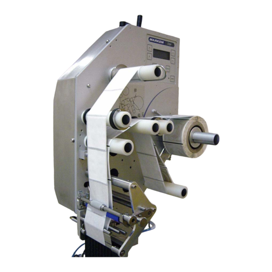
SECTION 1 General Information Overview The Cimjet RFID is a high speed, compact RFID tag dispenser and applicator. The key features of the Cimjet RFID are: Different applicator modules to suit specific applications - Front, top, side, or front and side apply. For more applicator... - Page 37 SECTION 1 General Information Figure 1–1 Cimjet RFID Dispenser (left-hand option shown) 1–25 ® 0855904enb 4/05...
-
Page 38: Components Of Cimjet Rfid
Tag drive • Sensors for tag control • Operator interface The dispenser is the main body of the Cimjet RFID and supports a variety of different mountable applicator modules. 3.1.2 Applicator Several modular applicators are available to meet your different requirements. - Page 39 SECTION 1 General Information Figure 1–2 Cimjet RFID - Front Figure 1–3 Cimjet RFID - Rear 1–27 ® 0855904enb 4/05...
- Page 40 SECTION 1 General Information Figure 1–4 Cimjet RFID - Tag Optic 1–28 ® 0855804enb 4/05...
-
Page 41: Beacon Light (Optional)
The beacon light is situated in a prominent position on the Cimjet RFID. The beacon has a three light system: green, blue, yellow. • When the yellow light is on, the Cimjet RFID has switched out of Auto Mode (to Set Mode) or there is a fault on the machine •... -
Page 42: Dimensional Drawings (In Millimeters)
SECTION 1 General Information Dimensional Drawings (in Millimeters) Figure 1–5 Cimjet RFID - Dispenser (applicator not shown) 1–30 ® 0855804enb 4/05... - Page 43 SECTION 1 General Information Figure 1–6 Cimjet RFID - Dispenser Stand 1–31 ® 0855904enb 4/05...
- Page 44 SECTION 1 General Information 1–32 ® 0855804enb 4/05...
-
Page 45: Section 2 Installation Guide
SECTION 2 Installation Guide Cimjet ® RFID ® Operation/Service Manual... -
Page 47: Installation Of The Cimjet Rfid
SECTION 2 Installation Guide Installation of the Cimjet RFID Installation should only be performed by qualified and trained personnel; customer installation should be sanctioned by MARKEM. WARNING: Failure to perform installation as stated above will invalidate the machine warranty. Installation Requirements Ensure that the required services and control signals are available: •... -
Page 48: Power
SECTION 2 Installation Guide Power The power connector (Type STASEI2) is supplied with the machine and conforms to EC regulations. Power Configuration Before installing the machine, check that the power supply is correctly configured. The power supply is configured by: •... -
Page 49: Air Requirements
SECTION 2 Installation Guide Air Requirements A compressed air supply is normally required by the Cimjet RFID to drive the applicator module. This must be set to 6.2 Bar (90psi) with a minimum flow rate of 4cfm (cubic feet per minute) (113 liters/ minute) and should be dry, uncontaminated air which should not be lubricated. -
Page 50: I/O Interface
Installation drawings are available which show the range over which the Cimjet RFID can apply tags. Refer to the previous pages in this section and also to Section 10 – Illustrations and Schematics. For more applicator information, refer to the Cimjet RFID Blow Applicator Manual (0855906) and the Cimjet RFID Tamp Applicator Manual (0855907). - Page 51 SECTION 3 Operating Guide Cimjet ® RFID ® Operation/Service Manual...
-
Page 53: Preparing Cimjet Rfid For Operation
The application cycles and type of apply sequence required would also be set up in the Cimjet RFID applicator parameters. For full details on connections, please consult Section 7 – Technical Information. - Page 54 SECTION 3 Operating Guide Figure 3–1 Webbing Diagram (left-hand option shown) 3–2 ® 0855904enb 4/05...
-
Page 55: Power-Up
• Press AUTO. • The Cimjet RFID automatically feeds Datum tags to set the correct tag stop position and measure the length of the tags in use. The number of tags varies with software versions. The message: REMOVE DATUM TAGS, THEN PRESS AUTO is displayed on the user interface. -
Page 56: Operator Interface
SECTION 3 Operating Guide Operator Interface Menu Operation The control panel (user interface) provides: • Machine setup and fault finding • Error and Warning Messages The Control Panel This drawing is a representation and is not to scale. Enter Exit •... -
Page 57: Operator Interface Leds
Mode LED Indicates if the machine is in Auto or Set Mode Green LED: Auto Mode Red LED: Set Mode Machine Yellow LED: Cimjet RFID is Busy LED feeding or applying in Auto Mode Status LED Green LED: Machine OK... -
Page 58: Auto And Set Mode
SECTION 3 Operating Guide Auto and Set Mode The Cimjet RFID has two modes of operation: • Auto Mode Cimjet RFID automatically responds to Apply signals. Application is triggered by sensors or other inputs. For further details, refer to the Cimjet RFID Section 7-Technical Information. -
Page 59: Auto Mode
SECTION 3 Operating Guide Auto Mode In Auto Mode, Cimjet RFID automatically applies tags. Application is triggered by sensors or other inputs such as PLC control. For details, refer to the Cimjet RFID Section 7-Technical Information. AUTO COUNTS TEST NEXT... -
Page 60: Set Mode
SECTION 3 Operating Guide Set Mode In Set Mode, Cimjet RFID does NOT respond to Apply requests. MODE SELECT PRODUCT ENGINEER MODE DATABASE PARAMETERS CIM3 TIME / MOVE DATE PRINT PARAMETER NEXT PREV CHANGE VIEW TIME / DATE DATE TIME... - Page 61 Control applicator parameters • Set the time and date Cimjet RFID has a further level of restricted access menus, which give access to other infrequently changed parameters. For further information, see Section 4 - Restricted Access Mode User Guide. To select Set Mode: •...
-
Page 62: Engineer Mode
TIMINGS Disp I/O This screen allows the operator to view the current status of the Cimjet RFID inputs and to test the various Cimjet RFID Outputs. Full details can be found in Section 7 – Technical Information. Set Tag Optic Cimjet RFID feeds tags to automatically determine the optimum setting for the tag sensor. -
Page 63: Parameters
SECTION 3 Operating Guide Parameters This option allows the operator to alter various operating parameters: TIME/ DATE PARAMETERS Time / Date VIEW TIME/DATE TIME DATE • Enter the required date and time Time is entered in the 24-hour format. 3–11 ®... -
Page 64: Section 4 Restricted Access Mode User Guide
It is used for positioning. Darkness* Feed Speed Feed speed (mm/s) is the time taken for the tag to pass the nip roll. Range: 50- 250mm/s Default: 15 0mm/s Direction* *Does not apply to Cimjet RFID 3–12 ® 0855904enb 4/05... - Page 65 SECTION 4 Restricted Access Mode User Guide Cimjet ® RFID ® Operation/Service Manual...
-
Page 67: Entering Restricted Access Mode
SECTION 4 Restricted Access Mode User Guide Restricted Access Mode User Guide The Restricted Access Mode in Cimjet RFID, has a series of menus. These menus allow the configuration to be altered. CAUTION: The accessed parameters should only require changing directly after installation. Access parameters must be changed by qualified MARKEM personnel or under close instruction from MARKEM. -
Page 68: Reset Params
SECTION 4 Restricted Access Mode User Guide Machine Init (Initialization) From the main menu: RESTRICTED MACHINE SETUP INIT PASSWORD CYCLE • Press MACHINE INIT The Machine Init menu is displayed: RESET CLEAR PARAMS DATABASE CLEAR COUNTS FLASH FILE Reset Params This option resets all parameters to their default values. -
Page 69: Password
When a password is enabled for a key, Cimjet RFID will request entry of the key sequence before allowing access to the option. The four levels are for access by different user types: •... -
Page 70: Password Configuration
SECTION 4 Restricted Access Mode User Guide Password Configuration On selection of the PASSWORD option from the top level restricted access menu, the following screen is displayed: CHANGE LEVEL 1 - ---- NEXT PREVIOUS • Select CHANGE; the following screen is displayed: ENABLE DISABLE LEVEL 1... - Page 71 SECTION 4 Restricted Access Mode User Guide In the above example, LEVEL 1 has access, via the level 1 password, to the SELECT PRODUCT option (Button 1). The underscores on the screen indicate which function button is associated with the button numbers shown at the beginning of this section.
-
Page 72: Password Key Sequences
SECTION 4 Restricted Access Mode User Guide Password Key Sequences The Key sequences for each access level are fixed and are as follows: • Level 1 – 2-1-1-1 • Level 2 – 2-3-3-1 • Level 3 – 4-1-2-3 • System 4 – 2-4-4-1 CAUTION: If you have password protection to restricted access mode, the SYSTEM user will automatically have access to this mode regardless of the SYSTEM... -
Page 73: Cycle
SECTION 4 Restricted Access Mode User Guide Cycle This cycle option allows the various elements of the machine to be set into continuous operation (for example: to continuously cycle the Cimjet RFID unit). See the main menu below: RESTRICTED MACHINE... -
Page 74: Set Parameters
SECTION 4 Restricted Access Mode User Guide Restricted Setup From the main menu: • Press RESTRICTED SETUP The following screen is displayed: SET NODES SELECT PARAMETERS LANGUAGE Set Parameters This option allows various parameters to be viewed and changed. From Restricted Setup menu: •... - Page 75 SECTION 4 Restricted Access Mode User Guide Communications Parameters These parameters configure the Communications port. From the Set Parameters screen: • Press COMMS FEEDER COMMS. MACHINE OPTIONS The first parameter is displayed: CHANGE EMULATION MODE CIMCOMMS NEXT PREVIOUS • Press CHANGE to select a different option See the following table for a full list of available communications parameters.
- Page 76 Network Node* Range: 1 to 31 Default: 1 (RS232 operation) Transfer Timeout This allows the Range: 30 seconds to 10 download transfer minutes timeout to be increased Default: 30 seconds *Does not apply to Cimjet RFID 4–10 ® 0855904enb 4/05...
-
Page 77: Machine Options Parameters
SECTION 4 Restricted Access Mode User Guide Machine Options Parameters These parameters configure the machine options available. From the Set Parameters screen: • Press MACHINE OPTIONS FEEDER COMMS MACHINE OPTIONS The following screen is displayed: APPLICATOR MACHINE CONFIG This screen provides access to: •... -
Page 78: Machine Configuration Parameters
From the Machine Option screen: • Press MACHINE CONFIG APPLICATOR MACHINE CONFIG The first parameter is displayed: CHANGE MACHINE TYPE CIMJET RFID NEXT PREVIOUS The options can be accessed by using the NEXT and PREVIOUS soft keys. 4–12 ® 0855904enb 4/05... - Page 79 334, 342, 344, 345, 346, 2112, 2113, 2132, 2341, 2422, Cimpak 300 Default: RFID Database Mode Cimjet RFID has two methods of product selection: Range: LOCAL RAM, Host Local RAM Mode: Cimjet RFID selects tags resident in Default: LOCAL RAM...
- Page 80 SECTION 4 Restricted Access Mode User Guide Table 4–2 Machine Configuration Parameters Parameter Description Allocation Warning If set to On, a warning is displayed when an allocation Range: Off, On runs out. Default: Off Measurement Units Style in which measurements are displayed, either Metric or Range: Metric, Imperial Imperial...
- Page 81 When a key is pressed, a ‘beep’ noise is produced. Range: Yes, No Default: No Note: For full information on the last five parameters, please see Section 7 – Technical Information. *Does not apply to Cimjet RFID 4–15 ® 0855904enb 4/05...
-
Page 82: Applicator Parameters
This parameter allows the Apply Delay application of the tag onto the Default: 25 pack to be delayed. Used for positioning. On Cimjet RFID, this is used to Head Lift Delay time the cylinder for the reject Default: 140 mechanism. Op Vacuum... -
Page 83: Feeder Parameters
SECTION 4 Restricted Access Mode User Guide 10.0 Feeder Parameters These parameters configure options in the Cimjet RFID for tag adjustment, motor speed, and optic sensor position. Table 4–4 Restricted Setup/Set Parameters/Feeder Parameter Description Darkness %* Default: 100 Backfeed Speed*... - Page 84 SECTION 4 Restricted Access Mode User Guide Table 4–4 Restricted Setup/Set Parameters/Feeder Parameter Description Feeder Hand Defines on which side of the Range: LEFT, feeder the image is aligned RIGHT Default: LEFT *Does not apply to Cimjet RFID 4–18 ® 0855904enb 4/05...
-
Page 85: Operating Modes
SECTION 5 Operating Modes Cimjet ® RFID ® Operation/Service Manual... -
Page 87: Application Cycle
SECTION 5 Operating Modes Operating Modes The Cimjet RFID can be fitted with various applicator modules to suit specific applications. The application may require that tags be applied to the top, front, side, front and side or top and side of the product packs. -
Page 88: Auto Apply Mode
SECTION 5 Operating Modes Auto Apply Mode The dispenser detects a product by using the Feed sensor, and begins to feed a tag. During feed, an air assist jet is used to ensure that the tag comes into contact with the applicator apply mechanism. The applicator may be in the form of a vacuum pad or belt-driven applicator. -
Page 89: Connecting External Sensors
SECTION 5 Operating Modes Connecting External Sensors Wiring the Sensors The Feed and Apply sensors are connected to Cimjet RFID via the 9 pin D type connector X23 on the rear of the machine. Depending upon the installation, different wiring configurations can be used. -
Page 90: Positioning Sensors
SECTION 5 Operating Modes Positioning Sensors Depending on the mode of operation, set via the Restricted Parameters menu, the Cimjet RFID can use a combination of Feed sensor only, Apply sensor only, or both Feed sensor and Apply sensor. The sensors must be positioned correctly to obtain the best possible results. -
Page 91: On Demand Mode Sensor Position
SECTION 5 Operating Modes On Demand Mode Sensor Position This option is used when the product conveyor is constantly stopping and restarting, or sometimes slows down due to the weight of the products. In On Demand Mode, a Feed sensor triggers the feeding of the tag and an Apply sensor triggers the application of the tag. -
Page 92: Fitting The Sensors
SECTION 5 Operating Modes Fitting the Sensors When the optimum position of the sensors is determined, mount the sensor firmly in place. Apply Delay The Apply Delay can either be set from the Set Mode Parameter screen or from the Restricted Access Mode screen. 5–6 ®... - Page 93 SECTION 6 Preventive Maintenance Guide Cimjet ® RFID ® Operation/Service Manual...
-
Page 95: Section 6 Preventive Maintenance Guide
This section describes cleaning and maintenance procedures which will help to keep the Cimjet RFID in good working condition. General Information Carry out a daily general machine inspection, which should include: •... -
Page 96: Cleaning Of All Rollers
Cleaning agents which will damage rubber or plastic MUST NOT be used. If in doubt, consult MARKEM. It is recommended that the rollers be cleaned regularly every time the tags are replaced and before using the machine if it has not been operated for several days. -
Page 97: Changing The Tag Size
SECTION 6 Preventive Maintenance Guide Changing the Tag Size When the tag width size is altered, check the following: • Reposition all the outer tag guide collars to suit the new tag size; the inner collar position should not be moved •... -
Page 98: Tag Unwind Brake
SECTION 6 Preventive Maintenance Guide Tag Unwind Brake A spring-loaded dancing arm and rubber friction brake band are used to control the tag supply. FIXING TO BASE PLATE WEB SUPPLY ROLLER SPRING FRICTION BAND SPRING WIPE DOWN ARM FIXING TO BASE PLATE Figure 6–1 Supply Reel Brake for Inside-wound Tags Each month, check for wear of the rubber friction brake band. -
Page 99: Clutches
SECTION 6 Preventive Maintenance Guide Clutches The web take-up roller uses slipping clutches to allow for the differing speeds of rotation required as the diameters of the web take-up change. A special oiled-felt material is used to provide the best performance over a long period. -
Page 100: Setting The Clutch Torque
SECTION 6 Preventive Maintenance Guide Setting the Clutch Torque At machine build, the clutch torques are set using a torque gauge. The following procedure should be used to set the torque when a replacement felt is fitted. Note: To set torque (refer to Figure 6-2): •... -
Page 101: Sensor Adjustment
SECTION 6 Preventive Maintenance Guide Sensor Adjustment Low Reel Sensor An optical sensor is used to detect when the supply reel diminishes below a set level. The sensitivity of the sensor is adjusted by a screw on the sensor. Nip Home Sensor The position of the nip arm is monitored to ensure that the feeder and nip arm are correctly in position before feeding starts. -
Page 102: Tag Gap Optic
Cimjet RFID uses stepper motors and will step these at either 8 steps/mm or 12 steps/mm. The backing web in the gap between tags will allow more light to pass through than the backing web and tags together. - Page 103 SECTION 6 Preventive Maintenance Guide To view the tag gap optic sensor output voltages: • Press ENGINEER Mode • Press DIAGNOSTICS • Press DISP I/O • Press NEXT; then scroll through the menu until you get to LABEL GAP Manually move the label through the sensor. Note the voltage when the sensor is looking through the gap (just webbing material) versus when it is looking through the label on the webbing material.
-
Page 104: Drive Belts
Loosen all four screws on the stepper motor • Remove the belt tension by rotating the eccentric cam; loosen the eccentric's fixing screw on the FRONT of the Cimjet RFID and rotate it using the tommy bar hole provided •... - Page 105 SECTION 6 Preventive Maintenance Guide To replace the web drive belt: Feed the belt into position. • Remember to tighten the motor screws before checking the belt tension • Do not put an excessive amount of tension on the belt as this places undue strain on the motor bearings and will lead to premature wear There should be approximately 15mm (.591”) of movement in the...
-
Page 106: Maintaining The Compressed Air
SECTION 6 Preventive Maintenance Guide Maintaining the Compressed Air The compressed air supply to the machine may contain moisture. A water trap is provided in the main pressure regulator, and this will require draining at regular intervals prior to machine use. Carry out the following procedures: •... -
Page 107: Technical Information
SECTION 7 Technical Information Cimjet ® RFID ® Operation/Service Manual... -
Page 109: Section 7 Technical Information
SECTION 7 Technical Information Power Configuration Before installing the Cimjet RFID, ensure that the power supply is correctly configured. The power supply is configured by: • Power connections to the Toroidal transformer located at the rear of the machine The Cimjet RFID is normally configured with the necessary power connections and fuse fitted to suit customer requirements. -
Page 110: Power Connections
SECTION 7 Technical Information Power Connections The power connections are made at the terminal located at the rear of the machine.The connection arrangement depends on the supply voltage. The machine can be configured for 115V or 230V by adding or removing the wire link provided. Connect the live (brown) wire, neutral (blue) wire and appropriate link as shown. -
Page 111: The Cimjet Rfid Main Processor Board
TP26 TB1, X29, X30 and X40 are on the other side of the Control Figure 7–3 Cimjet RFID Main Processor Board The main processor board is situated on the rear of the dispenser. This board provides all the processing power, I/O buffering and power for the feed control and general machine control for the Cimjet RFID. - Page 112 SECTION 7 Technical Information On-board Connectors Table 7–1 On-board Connectors Connector Function Main Power Connector – 12-way Expansion I/O Connector Head Lift Solenoid Totalizing Counter 1 – 24VSOL 2 – Output Gap Optic Drive 1 – Drive 2 – 0VA 3 –...
- Page 113 SECTION 7 Technical Information Table 7–1 On-board Connectors Connector Function Output #8 (N/C) – 2-way Molex Connector 1 – Signal 2 – 0VP Operator Interface Output #9 (N/C) – 2-way Molex Connector 1 – Signal 2 – 0VP Output #7 (N/O) – 2-way Molex Connector 1 –...
- Page 114 SECTION 7 Technical Information Table 7–1 On-board Connectors Connector Function Applicator Input #2 – 3-way Molex 1 – 24VS 2 – Signal 3 – 0VS Applicator Input #1 – 3-way Molex 1 – 24VS 2 – Signal 3 – 0VS External Host Comms Connector –...
-
Page 115: Input And Output Leds
SECTION 7 Technical Information Input and Output LEDs Table 7–2 Input LEDs Input LED Function Main Processor Board Feed and Apply Input Spare External Input # 1 E-stop Monitor Guards Monitor Applicator Input # 3 Spare External Input # 2 Low Paper Applicator Input # 1 Applicator Input # 2... - Page 116 SECTION 7 Technical Information Table 7–3 Output LEDs Output LED Function Main Processor Board LD10 Fault LD11 Warning LD12 Reject LD13 Busy LD14 Applicator Specific LD15 Applicator Specific LD16 Applicator Specific LD17 Applicator Specific LD18 Applicator Specific 7–8 ® 0855904enb 4/05...
-
Page 117: Processor Board Links
SECTION 7 Technical Information Processor Board Links Table 7–4 Processor Board Links Link Number Function Battery Link Dump Valve Link (Default Link in) Remove this link to enable remote dump valve control via X12 connector For links LK4 to LK8, configure respective outputs for: Link positions –... - Page 118 SECTION 7 Technical Information Table 7–4 Processor Board Links Link Number Function Bootstrap link (Program upgrade via RS232) LK17 A = Default B = Bootstrap enabled 7–10 ® 0855904enb 4/05...
-
Page 119: Test Points
SECTION 7 Technical Information Test Points WARNING: Only qualified personnel are allowed to use the Test Points to check the board operation. All precautions must be taken to prevent possible injury and/or damage to the product. Table 7–5 Test Points Test Point Function 0V (Logic supply) - Page 120 SECTION 7 Technical Information Table 7–5 Test Points Test Point Function 232/485 – Output for RS232/485 TP23 Selection for Comms Port (Active High for RS232) TX Data (TXD0) – Comms Port TP24 RS232 Output Data RX Data (RXD0) – Comms Port TP25 RS232 Input Data +VM –...
-
Page 121: Fuses
SECTION 7 Technical Information Fuses Table 7–6 Fuses Fuse Function 24V I/O and Beacon Supplies – 1.35A 24V Solenoid Supply – 0.75A 24V SPI Supply – 0.75A 24V Sensors Supply – 0.75A Motor/Reject Supply – 4A 5V Isolated Supply – 0.17A 5V and 24V Supplies –... -
Page 122: Firmware And Ram
SECTION 7 Technical Information Firmware and RAM The Cimjet RFID board supports three different options for machine control software. The software is stored in two ROMS. These will either be Flash ROM or EPROM and will be tagged with a “P”... -
Page 123: Switch Settings And Potentiometers
SECTION 7 Technical Information Switch Settings and Potentiometers SW1 Board Reset Potentiometers RV1 and RV2 These are used to set the voltage levels for the Tag Gap sensor. The default settings are characteristic of standard tags but may not be appropriate for all applications. The voltage settings can be viewed on the Engineer Mode Diagnostics Screen, and the appropriate adjustments can be made to the voltage potentiometer by passing a tag with backing web, or... -
Page 124: External Connectors
SECTION 7 Technical Information External Connectors Input and output connectors are provided on the rear of the Cimjet RFID. CAUTION: It is essential that the connector dust covers pro- vided with the machine are fitted to all unused connectors to protect against dust and prevent possible static damage to internal components. -
Page 125: X28 Communications (Comms)
PLC and is also used for Emulation Mode. Figure 7–4 shows suitable RS232 cables for connecting your PC to the Cimjet RFID. For RS485 wiring details, please refer to Section 10 – Parts Illustrations and Schematics. Table 7–7 Comms Port Connections... -
Page 126: X23 External Sensor Connection
SECTION 7 Technical Information X23 External Sensor Connection This is a 9-pin miniature D-type connector. The X23 sensor port provides connection to external sensors, such as the Feed and Apply sensors. The wiring requirements depend on the type of applicator used. Table 7–8 External Sensor Connections Description Number... -
Page 127: X12 External I/O
The N/O or N/C state indicates the state of the circuit when the Cimjet RFID is powered up and operating in a fault/warning free condition. - Page 128 SECTION 7 Technical Information Table 7–9 Safety Module Connections Pin Number Description Volt-free Mode +24V Mode Ready (RDY) (N/O) Ready (+24V) (LK4) Ready (C) Fault (N/O) Fault (+24V) (LK5) Fault (C) Fault (N/C) Fault (+24V) Warning (N/O) Warning (+24V) (LK6) Warning (C) Warning (N/C) Warning (+24V)
-
Page 129: Status Output
• An example is when the Cimjet RFID has completed feeding the last tag or when the Cimjet RFID has completed an apply cycle; the status output can then be reset by one of the user options in the restricted access menu, machine configure parameters. -
Page 130: Status Reset Input
For example, it may be necessary for the external control system to know when the Cimjet RFID has finished feeding the last tag in order for it to accept the next feed tag signal. The Status Output can be configured to do this. -
Page 131: Display I/O
SECTION 7 Technical Information Display I/O The Diagnostic Display I/O function allows the operator to monitor the status of the machine inputs and to activate the machine outputs for testing purposes. These functions can be accessed from the Engineer Mode screen under Diagnostics. - Page 132 SECTION 7 Technical Information Inputs The functionality of various sensors and other inputs can be tested by viewing their status on the Engineer Mode - Diagnostic screen. • Select Disp I/O from the Engineer Mode - Diagnostic screen DISP I/O TIMINGS The inputs screen is displayed: INPUTS...
- Page 133 SECTION 7 Technical Information Table 7–10 Diagnostic Screen - Inputs Input Description Indicates the condition of the Sensor signal to start the feed or Feed feed and apply sequence Status: On/Off Spare Input Applicator-specific Spare Input Applicator-specific Spare Input Applicator-specific Indicates the condition of the Sensor signal to start the apply Apply...
- Page 134 Displays the current release of Software firmware being used in the Version machine, such as P2850 - 11/07/01 Board Displays the type of processor Revision board fitted, such as REV D *Does not apply to Cimjet RFID 7–26 ® 0855904enb 4/05...
-
Page 135: Inputs
SECTION 7 Technical Information Outputs • Select Disp I/O from the Engineer Mode - Diagnostic screen DISP I/O TIMINGS To select the Outputs screen: • Press the soft key next to INPUTS INPUTS FEED NEXT PREVIOUS The Outputs screen is displayed: OUTPUTS TOGGLE READY... - Page 136 SECTION 7 Technical Information Table 7–11 Diagnostic Screen - Outputs Output Description An input for the conveyor PLC or for a Ready Beacon lamp An input for the conveyor PLC or for a Warning Beacon lamp An input for the conveyor PLC or for a Reject Beacon lamp An input for the conveyor PLC or for a...
-
Page 137: Pneumatics
SECTION 7 Technical Information Pneumatics Air Requirements A compressed air supply is required by the Cimjet RFID to drive the applicator module. This must be air at 6 Bar and should be: dry, uncontaminated air, and not lubricated. A filter regulator assembly is fitted to the base of the stand; this is comprised of a manual isolation valve, a water trap, pressure regulator, and dump valve. - Page 138 SECTION 7 Technical Information (Plug on Cimjet RFID) TO DISPENSER TO APPLICATOR Figure 7–5 Air Filter/Regulator Unit A 6mm (.236”) push fitting is provided to accept flexible pipe. The supply should be at 6.2 Bar (90psi). It should also be dry, clean, and not lubricated.
- Page 139 SECTION 7 Technical Information The Tag Reject Mechanism has a separate air regulator which is mounted inside the dispenser cover next to the solenoid valve that operates it. Figure 7–6 Air Regulator and Solenoid Valve for Tag Reject Mechanism The air pressure for the Tag Reject Mechanism does not normally have to be adjusted and should be set to 3.5 to 4.0 Bar.
- Page 140 SECTION 7 Technical Information 7–32 ® 0855904enb 4/05...
-
Page 141: Troubleshooting Guide
SECTION 8 Troubleshooting Guide Cimjet ® RFID ® Operation/Service Manual... -
Page 143: Section 8 Troubleshooting Guide
SECTION 8 Troubleshooting Guide Error Messages in Auto Mode If a fault occurs, the Cimjet RFID comes out of Auto Mode and the error message is displayed. This includes a suggestion on how to clear the fault. For example: FAULT 03: NIP OPEN... -
Page 144: Power-Up Error Messages
SECTION 8 Troubleshooting Guide Power-up Error Messages These errors can be generated when the Cimjet RFID is powered up. If the battery backed RAM is corrupt, one of the following messages will be displayed: Table 8–1 Power-up Error Messages Message... -
Page 145: Start-Up Error Messages
Parameters Ensure that the nip roller has been Nip Open secured back in place The Cimjet RFID has detected that there are tags missing from the web. This can Missing Tag cause products to be untagged. Check the tag stock for missing tags and replace the reel if necessary. -
Page 146: Other Error Messages
SECTION 8 Troubleshooting Guide Other Error Messages You may see other errors, such as a CYLINDER FAULT, which are associated with the applicator. A complete list of all Cim* series machine error messages follows: Table 8–3 Other Error Messages Fault Description/Action Number NO WEB... - Page 147 SECTION 8 Troubleshooting Guide Table 8–3 Other Error Messages NO PRODUCT DETECTED PRESS AUTO WARNING: ALLOCATION COMPLETED SEND NEW ALLOCATION OR PRESS AUTO TO CLEAR APPLICATOR ARM NOT HOME PRESS AUTO NO TAG HAS BEEN DETECTED ON THE APPLICATOR PRESS AUTO PAD HAS FAILED TO RETURN HOME PRESS AUTO...
- Page 148 SECTION 8 Troubleshooting Guide Table 8–3 Other Error Messages PLC MODE/CYCLE 2 DETECTED/ NO CYCLE 2 DEFINED PRESS AUTO HOST PRINT/CYCLE 2 DETECTED/ NO CYCLE 2 DEFINED PRESS AUTO 8–6 ® 0855904enb 4/05...
-
Page 149: Communications Problems
Communications Speed (Baud Rate) This is set in Restricted Access Mode Data Bits, Stop Bits and Parity Cimjet RFID always uses 8 data bits, 1 stop bit and No parity • The Cimjet RFID is set for the correct communications type, such as RS232 or RS485 •... -
Page 150: Tag Feed Problems
SECTION 8 Troubleshooting Guide Tag Feed Problems Tag feed problems can be caused by several things such as: • Machine being incorrectly webbed • Drive belts slipping • Stepper motor stalling • Faulty gap sensor • Incorrect parameter settings If, for example, the stopping position was consistently wrong, the most likely cause would be the parameter settings, such as the feed distance. -
Page 151: Inconsistent Tag Stopping Position
SECTION 8 Troubleshooting Guide Inconsistent Tag Stopping Position 6.3.1 If the Tag Stops in the Correct Position If the tag stops in the correct position when datum tags are fed, but the stop position is inconsistent after this, do the following: •... -
Page 152: No Driving Of Tags
SECTION 8 Troubleshooting Guide No Driving of Tags Check the following: • Ensure that the clutches are operating correctly • Check for broken drive belts • If there is no motor voltage, check fuses and motor voltage test point • Ensure the external motor control link is in position - LK9 on the main PCB Motor Stalling... -
Page 153: Recommended Spares
SECTION 9 Recommended Spares Cimjet ® RFID ® Operation/Service Manual... -
Page 155: Preventive Maintenance Spares Kits
SECTION 9 Recommended Spares Recommended Spares Preventive Maintenance Spares Kits are listed below. These are followed by General Spares Kits. Preventive Maintenance Spares Kits Table 9–1 Roller Cleaning Part No. Description 5824648 Cleaning Pads Table 9–2 Maintenance Parts – 100mm (3.94”) Part No. -
Page 156: General Spares Kits
SECTION 9 Recommended Spares General Spares Kits Table 9–3 Basic Spares Dispenser Parts Part No. Description 31A104A Tag Gap Sensor 5943412 Nip Latch Knob 31A58A Nip Sensor B03876AA Low Web Sensor B04297AA Spare Main Fuse (T5A) 32621BB Operator Panel Assembly 35146BA LCD Display Assembly 5564342... - Page 157 Section 10 Parts Illustrations and Electrical Schematics Cimjet ® RFID ® Operation/Service Manual...
Need help?
Do you have a question about the Cimjet RFID and is the answer not in the manual?
Questions and answers