
Related Manuals for Altai Technologies A8n (ac)

Summary of Contents for Altai Technologies A8n (ac)
- Page 1 Installation Guide Version 1.2 Altai A8n (ac) Series Super WiFi Base Station Altai Technologies Ltd. All rights reserved...
- Page 2 Altai A8n (ac) Series Super WiFi Base Station Installation Guide Copyright © 2015 Altai Technologies Limited ALL RIGHTS RESERVED. Altai Technologies Limited Unit 209, 2/F, Lakeside 2, 10 Science Park West Avenue, Hong Kong Science Park, Shatin, New Territories, Hong Kong...
- Page 3 Consult the dealer or an experienced radio/TV technician for help. FCC Caution: To assure continued compliance, (example – use only shielded interface cables when connecting to computer or peripheral devices). Any changes or modifications not expressly approved by the Altai Technologies Ltd. All rights reserved...
- Page 4 This document is provided for information purposes only. Altai Technologies reserves the right to change, modify, transfer, or otherwise revise this publication without notice. Altai Technologies Ltd. All rights reserved...
-
Page 5: Table Of Contents
RF CABLES CONNECTION AND MOUNTING OF 5GHZ RADIO ANTENNA ..........15 WEATHERPROOFING A8N (AC) SERIES RADIO ANTENNA ..............16 RECOMMENDATION ON INSTALLATION POLE .................. 22 GROUNDING PROTECTION ....................... 23 ETHERNET CONNECTOR PACKET INSTALLATION ................24 LIGHTNING PROTECTION........................28 Altai Technologies Ltd. All rights reserved... -
Page 6: Introduction
It is a good practice to have a document consists of a map and drawing illustrating the base station and poles locations, antenna bearing/down-tilt, antenna height, etc… A planning on IP network is also an important issue for network planning. Altai Technologies Ltd. All rights reserved... -
Page 7: A8-Ein (Ac) Base Station Mounting And Outlook
Altai A8n (ac) Series Super WiFi Base Station Installation Guide A8-Ein (ac) Base Station Mounting and Outlook Mounting screw Locking screw hole 5GHz Port Grounding Screw Ethernet Port Figure 1. back-view of A8-Ein (ac) Altai Technologies Ltd. All rights reserved... -
Page 8: Reset Back To Factory Default Via Reset Button
Continue pressing the button until you see Power LED blink twice consecutively o Then release it immediately Blink once Blink twice Press&Hold Release here Release here Time (s) trigger trigger Soft-reboot Reset Factory Altai Technologies Ltd. All rights reserved... - Page 9 Altai A8n (ac) Series Super WiFi Base Station Installation Guide The reset button’s location is shown in following. Altai Technologies Ltd. All rights reserved...
-
Page 10: A8-Ein (Ac) Base Station Mounting Kit
Altai A8n (ac) Series Super WiFi Base Station Installation Guide A8-Ein (ac) Base Station Mounting Kit Main mounting module Mounting back plate 4x mounting screw and nut 4x locking screw Figure 3. A8-Ein (ac) Base Station Package Altai Technologies Ltd. All rights reserved... -
Page 11: Mounting A8-Ein (Ac) On Pole
(Figure 9). 7. The mounting kit will fit with pole diameter from 1 inch to 3 inches. Figure 4. Mounting kit assembly Figure 5. Mounting kit assembly Figure 6. Key hole direction Altai Technologies Ltd. All rights reserved... - Page 12 Altai A8n (ac) Series Super WiFi Base Station Installation Guide Figure 7. Clamping A8-Ein (ac) unit Figure 8. Secure the unit Tilting Screws Figure 9. Antenna Mounted on Pole Altai Technologies Ltd. All rights reserved...
-
Page 13: A8N (Ac) And A8In (Ac) Base Station Mounting
Mounting for A8n (ac) and A8in (ac) are the same. Figure 10 shows the back view of A8in (ac). A8n (ac) has the same mounting screw. Mounting screw Grounding Ethernet Port 5GHz Port Screw Figure 10. back-view of A8in (ac) Altai Technologies Ltd. All rights reserved... -
Page 14: A8N (Ac) And A8In (Ac) Base Station Mounting Kit
A8n (ac) and A8in (ac) Base Station Mounting Mounting back plate Main mounting module 4x mounting screws and nuts 4x locking screws and nuts Figure 11 A8n (ac) and A8in (ac) Base Station Package Altai Technologies Ltd. All rights reserved... -
Page 15: Mounting A8N (Ac) And A8In (Ac) On Pole
6. The mounting kit will fit with pole diameter from 1 inch to 3 inches. Figure 12 Mounting kit assembly Figure 13 Completion of Mounting Figure 14 mounting screw locking direction Figure 15 Clamping and secure the unit on pole Altai Technologies Ltd. All rights reserved... -
Page 16: Mounting A8N (Ac) 2.4Ghz Antenna And Cable Connection
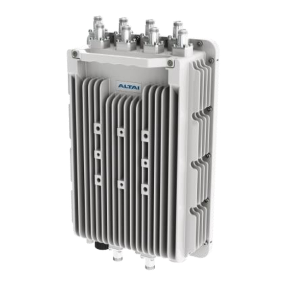
3. It is recommended to seal the A8n (ac) series RF ports with weatherproof materials to prevent water leakage. Figure16. Top of A8n (ac) – 8 N-female RF port for external 2.4GHz panel antenna connection Altai Technologies Ltd. All rights reserved... -
Page 17: Mounting Of A8N (Ac) 2.4Ghz Panel Antenna
2. Adjust the direction and down-tilt angle of the A8n (ac) 2.4GHz antenna to align, as shown in Figure 18. Figure 17. Standard A8n (ac) 2.4GHz Antenna Figure 18. Adjust A8n (ac) 2.4GHz Antenna tilting Altai Technologies Ltd. All rights reserved... -
Page 18: Cable Connection From A8N (Ac) To 2.4Ghz Panel Antenna
3. It is recommended to seal the A8n (ac) series 2.4GHz antenna RF ports with weatherproof materials to get the best performance according to the procedure in chapter 6 of this document. Figure19. RF cable connection from panel antenna Altai Technologies Ltd. All rights reserved... - Page 19 Altai A8n (ac) Series Super WiFi Base Station Installation Guide Figure 20. Antenna port to A8n (ac) port mapping Sector Sector Sector Sector Figure21. A8n (ac) 2.4GHz RF port groups Altai Technologies Ltd. All rights reserved...
-
Page 20: Rf Cables Connection And Mounting Of 5Ghz Radio Antenna
6 of this document 5GHz Port Figure 22. 5GHz “a0 & a1” antenna RF ports Figure 23. 20dBi 5GHz Antenna mounting Figure 24. Waterproof wrapping direction Altai Technologies Ltd. All rights reserved... -
Page 21: Weatherproofing A8N (Ac) Series Radio Antenna
A layer of butyl rubber tape is applied around a connector joint to provide a weatherproof seal, often on top of a layer of electrical tape. We recommend the Andrew Corporation butyl rubber tape for this purpose. Altai Technologies Ltd. All rights reserved... - Page 22 This will provide the same effect as shingles on a house. The water will run down across the joints without going into the joints. In order to properly weatherproof of the BTS radio antenna ports, they must be prepared before the installation. Altai Technologies Ltd. All rights reserved...
- Page 23 RF cable connector around the antenna port. Figure 27. Wrap the Butyl Rubber Strip Figure 28. Butyl Rubber Ring Finished Connecting RF Cables 1. Make sure each RF cable and its connectors are absolutely dry. Altai Technologies Ltd. All rights reserved...
- Page 24 The tape can be applied in one or more strips if necessary. A strip can be coiled onto an applicator such as a pencil. Apply only enough tension to get good adhesion and keep the tape smooth. Altai Technologies Ltd. All rights reserved...
- Page 25 Overlap the tape to half –width. Finish the wrap at the base of the antenna port and cut the tape. Take extra care to make sure that the RF cable connector to A8n (ac) series 5GHz Altai Technologies Ltd. All rights reserved...
- Page 26 Finish the wrap at the base of the A8n (ac) series 5GHz antenna RF port and cut the tape. Repeat this process for a second layer, and if enhanced UV protection is required, a third layer. Altai Technologies Ltd. All rights reserved...
-
Page 27: Recommendation On Installation Pole
1.5 inches to 3 inches. Remark: 2 inches pole is recommended as A8n (ac) series base station and external antenna can be installed on the same pole. Figure 30. At Least 1m above Any Obstacle in Front Altai Technologies Ltd. All rights reserved... -
Page 28: Grounding Protection
2. Attach a length 10 AWG bare copper with a terminal connector to the grounding screw. 3. Tighten the screw nut. 4. Connect the other end of grounding wire to grounding rods or earth ground. Grounding Screw Figure 31 Grounding Screw Altai Technologies Ltd. All rights reserved... -
Page 29: Ethernet Connector Packet Installation
Ethernet Connector Packet Installation The Ethernet connector packet includes the following components: 1. Gasket 2. Housing 3. Screw Nut 4. Clamping Ring Gasket & Screw Nut Clamping Ring Housing Mount the housing and screw Altai Technologies Ltd. All rights reserved... - Page 30 Altai A8n (ac) Series Super WiFi Base Station Installation Guide Mount the housing, screw nut and clamping ring Pass the housing and clamping ring through the cable and tight up the clamping ring Altai Technologies Ltd. All rights reserved...
- Page 31 Cat 5e or cat 6 Ethernet cable are recommended. Maximum cable length between PoE adapter and A8n (ac) is 100m. The end of cable, RJ-45 modular jack pins are numbered 1 through 8 as shown: _______________________________ |_____ Face of Plug ______| |____ ____| |________| Altai Technologies Ltd. All rights reserved...
- Page 32 Installation Guide The assignments of wire pairs to plug and jack pins are as follows : Pair wire Color white / orange orange white / green blue white / blue green white / brown brown Altai Technologies Ltd. All rights reserved...
-
Page 33: Lightning Protection
It does not prevent lightning from striking but provides a means for controlling it and prevents damage by providing a low resistance path for discharge of the lightning energy. Altai Technologies Ltd. All rights reserved... - Page 34 AWG 0 copper conductor is recommended for the ground conductor. Aluminum or iron conductor can also be used but with poorer conductivity. Minimum cross sectional area of copper, aluminum and iron ground conductor are 16, 25 and 30 mm respectively. Altai Technologies Ltd. All rights reserved...
- Page 35 External Lightning Protectors Lightning protector (or surge arrestor) is a component which provides a lower resistance path to conduct sufficient charge from the surge in order to lower the surge voltage to a safe level. Altai Technologies Ltd. All rights reserved...
- Page 36 The implementation of the suggested measures is at the customer’s own discretion. Under no circumstances will Altai be liable for any consequences resulting from the implementation or lack of implementation of the suggested measures. Altai Technologies Ltd. All rights reserved...
Need help?
Do you have a question about the A8n (ac) and is the answer not in the manual?
Questions and answers