
Related Manuals for Altai Technologies A8N SERIES

Summary of Contents for Altai Technologies A8N SERIES
- Page 1 ALTAI A8N SERIES SUPER WIFI BASE STATION INSTALLATION GUIDE Version 1.0 () Date: September, 2013 Altai Technologies Ltd. All rights reserved...
- Page 2 A8n Series Super WiFi Base Station Installation Guide TPS13-002_rev1.0 Copyright © 2007 Altai Technologies Limited ALL RIGHTS RESERVED. Altai Technologies Limited Unit 209, 2/F, East Wing, Building 17, Hong Kong Science Park, Shatin, New Territories, Hong Kong Telephone: +852 3758 6000...
- Page 3 This document is provided for information purposes only. Altai Technologies reserves the right to change, modify, transfer, or otherwise revise this publication without notice.
-
Page 4: Table Of Contents
Introduction ............................ 18 6.2. Connecting RF Cables ......................... 21 6.3. Weatherproofing on A8n 2.4GHz Radio Antenna Ports............21 6.4. Weatherproofing A8n series 5GHz Antenna RF Ports ............. 22 ....................23 ECOMMENDATION ON NSTALLATION 7.1. Antenna Pole Height and Size ....................23 7.2. -
Page 5: Introduction
TPS13-002_rev1.0 1. Introduction This guide is designed to provide the information needed to mount A8n Series Base Station (BTS) at the site location. A8n series contains 3 variants: 1) A8n: contains A8n base station plus 4 external 2.4GHz 14dBi panel antennas. Each panel antenna can adjust direction and tilt. -
Page 6: A8-Ein Base Station Mounting Kit
A8n Series Super WiFi Base Station Installation Guide TPS13-002_rev1.0 Figure 2-1 Back-View of A8-Ein Figure 2-2 Bottom-View of A8-Ein 2.2. A8-Ein Base Station Mounting Kit Main mounting module Mounting back plate Altai Technologies Ltd. All rights reserved... -
Page 7: Mounting A8Ein On Pole
A8n Series Super WiFi Base Station Installation Guide TPS13-002_rev1.0 4x mounting screw and nut 4x locking screw Figure 2-3 A8Ein Mounting Kit Packages 2.3. Mounting A8Ein on Pole Assemble the mounting kit according to Figure 2-4 with one side of the screw installed. - Page 8 A8n Series Super WiFi Base Station Installation Guide TPS13-002_rev1.0 Figure 2-4 Mounting kit assembly Figure 2-5 Mounting kit assembly Figure 2-6 Key hole direction Altai Technologies Ltd. All rights reserved...
- Page 9 A8n Series Super WiFi Base Station Installation Guide TPS13-002_rev1.0 Figure 2-7 Clamping A8Ein unit Figure 2-8 Secure the unit Altai Technologies Ltd. All rights reserved...
-
Page 10: A8N And A8In Base Station Mounting
A8n Series Super WiFi Base Station Installation Guide TPS13-002_rev1.0 Tilting Screws Figure 2-9 Antenna Mounted on Pole 3. A8n and A8in Base Station Mounting Mounting for A8n and A8in are the same. Figure 10 shows the back view of A8in. A8n has the same mounting screw. -
Page 11: A8N And A8In Base Station Mounting Kit
A8n Series Super WiFi Base Station Installation Guide TPS13-002_rev1.0 Figure 3-1 Back-View of A8in 3.1. A8n and A8in Base Station Mounting Kit Mounting back plate Main mounting module 4x mounting screws and nuts 4x locking screws and nuts Altai Technologies Ltd. All rights reserved... -
Page 12: Mounting A8N And A8In On Pole
A8n Series Super WiFi Base Station Installation Guide TPS13-002_rev1.0 Figure 3-2 A8n and A8in Base Station Package 3.2. Mounting A8n and A8in on Pole Assemble the mounting kit according to Figure 3-3 with one side of the screw installed. Mount the kit to the pole at the desired height and tighten all 4 screws to fix its position (Figure 3-4). - Page 13 A8n Series Super WiFi Base Station Installation Guide TPS13-002_rev1.0 Figure 3-4 Completion of Mounting Kit Figure 3-5 mounting screw locking direction Figure 3-6 Clamping and secure the unit on pole Altai Technologies Ltd. All rights reserved...
-
Page 14: Mounting A8N 2.4Ghz Antenna And Cable Connection
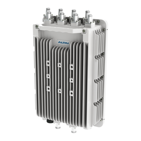
At the top of A8n, there are 8 N-female RF connector marked with 1-8. They are grouped to 4 groups to connect to 4 external 2.4GHz panel antenna. It is recommended to seal the A8n series RF ports with weatherproof materials to prevent water leakage. -
Page 15: Cable Connection From A8N To 2.4Ghz Panel Antenna
A8n port to antenna port according Figure 4-5 mapping. It is recommended to seal the A8n series 2.4GHz antenna RF ports with weatherproof materials to get the best performance according to the procedure in chapter 6 of this document Altai Technologies Ltd. - Page 16 A8n Series Super WiFi Base Station Installation Guide TPS13-002_rev1.0 Figure 4-4 RF cable connection from panel antenna Figure 4-5 Antenna port to A8n port mapping Altai Technologies Ltd. All rights reserved...
-
Page 17: Rf Cables Connection And Mounting Of 5Ghz Radio Antenna
Antenna The standard A8n series 5GHz antenna has two RF ports. Connect RF cables from the A8n series 5GHz antenna RF ports which marked “a0” and “a1”next to the RF ports. It is recommended to seal the A8n series 5GHz antenna RF ports with... -
Page 18: Weatherproofing A8N Series Radio Antenna
1. High-quality, all-weather, black plastic electrical tape, preferably 3/4” (19mm) wide to make it easier to manipulate the tape around the A8n Series BTS radio antenna ports. An RF port is often first wrapped with a layer of electrical tape to make it easier to remove the butyl rubber layer. - Page 19 3M Scotch Super 88 Vinyl Electrical Tape for this purpose. 2. High-quality, all-weather, black butyl rubber tape, preferably 3/4” (19mm) wide to make it easier to manipulate the tape around the A8n series BTS radio antenna ports. Butyl rubber tape is self-amalgamating - it chemically bonds to itself, forming a strong, waterproof joint.
- Page 20 A8n Series Super WiFi Base Station Installation Guide TPS13-002_rev1.0 5. In warm climates where there will be long exposure to sunlight, it is a good idea to wrap an extra layer or two of electrical plastic tape over the butyl rubber layer to enhance UV protection.
-
Page 21: Connecting Rf Cables
3. Secure the RF cable bundles to the pole. 4. Tighten the RF cable connectors around the A8n series 5GHz antenna ports with a torque wrench to the proper torque limit to ensure that correct internal seals and surface contacts are made. If a torque wrench is not available, first tighten the connector to finger tight, then tighten it with a wrench for an additional ⅛... -
Page 22: Weatherproofing A8N Series 5Ghz Antenna Rf Ports
Figure 6-5 Wrapping direction and extends the wrap 1” above the connector clamping 2. Start wrapping a layer of butyl rubber tape from the base of the A8n series 5GHz antenna port. Overlap the tape to half –width. Finish the wrap at 1” (25mm) above the electrical tape and cut the tape. -
Page 23: Recommendation On Installation Pole
3. Start wrapping a layer of electrical tape 1” (25mm) below the butyl rubber tape, overlapping at half-width. Finish the wrap at the base of the A8n series 5GHz antenna RF port and cut the tape. Repeat this process for a second layer, and if enhanced UV protection is required, a third layer. -
Page 24: Ethernet Connector Packet Installation
National Electric Code. The grounding screw is located at the bottom of A8n series as showed in figure 30. Use 10 AWG wire with corrosion-resistant connectors for connecting to one or more approved grounding rods or building’s earthling network. - Page 25 A8n Series Super WiFi Base Station Installation Guide TPS13-002_rev1.0 Altai Technologies Ltd. All rights reserved...
- Page 26 A8n Series Super WiFi Base Station Installation Guide TPS13-002_rev1.0 Cat 5e or cat 6 Ethernet cable are recommended. Maximum cable length between PoE adapter and A8n is 100m. The end of cable, RJ-45 modular jack pins are numbered 1 through 8 as shown:...
-
Page 27: Lightning Protection
A8n Series Super WiFi Base Station Installation Guide TPS13-002_rev1.0 The assignments of wire pairs to plug and jack pins are as follows: Pair wire Color white / orange orange white / green blue white / blue green white / brown... - Page 28 It does not prevent lightning from striking but provides a means for controlling it and prevents damage by providing a low resistance path for discharge of the lightning energy. A typical lightning protection system for A8n series base station is shown in Figure 24. It consists of 5 parts: ...
- Page 29 A8n Series Super WiFi Base Station Installation Guide TPS13-002_rev1.0 External Lightning Protectors 1) Lightning Rod A lightning rod (air terminal) neutralizes the downward lightning strike by launching an upward ionized path. The lightning current will follow this path and is thus diverted away from personnel and electronic equipment.
- Page 30 A8n series base station embedded protectors. They can be put at strategic points such as the Ethernet port, AC power or antenna ports close to the A8n series base station. External lightning protectors are available in the market in the form of a protector box, which can be inserted simply in front of the ports to be protected.
- Page 31 A8n Series Super WiFi Base Station Installation Guide TPS13-002_rev1.0 While this section gives a general guideline on lightning protection, the detail specifications of a lightning protection system must be provided by local electricians and must be maintained and checked periodically in accordance with local regulations.
Need help?
Do you have a question about the A8N SERIES and is the answer not in the manual?
Questions and answers