
Related Manuals for Sonus 5200


Summary of Contents for Sonus 5200
- Page 1 Hardware Installation Guide Session Border Controller 5200 Sonus Part Number: 550-02545 Sonus Technical Publication Document Version: Beta 1 www.sonusnet.com Software Version: V03.00.00...
- Page 2 Copyright © 1999 - 2012 Sonus Networks, Inc. All rights reserved. This item and the information contained herein are the property of Sonus Networks, Inc. This publication may be used, copied, or distributed only in accordance with the terms of the license agreement. Any other use, reproduction, or distribution may occur only upon Sonus’ prior written consent.
- Page 3 Use of the information in this publication is governed by all applicable federal, state, and local laws. All information available in this publication is subject to U.S. export control laws and may also be subject to the laws of the country where you reside. Sonus Networks makes no representation that the content on this site is appropriate or available for use in other locations, and access to it from territories where the content is illegal and prohibited.
-
Page 5: Table Of Contents
Quickstart Installation of the SBC 5200 Platform ........ - Page 6 Establishing Connections to the SBC 5200 Platform ....... . 2-29...
- Page 7 Post Installation Checklist ............A-3 550-02545 — Beta Version 1 — Release V03.00.00 1–iii © 2012 Sonus Networks, Inc. Confidential and Proprietary. All Rights Reserved. Do not distribute without permission.
- Page 8 Hardware Installation Guide 1–iv © 2012 Sonus Networks, Inc. Confidential and Proprietary. All Rights Reserved. Do not distribute without permission.
-
Page 9: About This Guide
The SBC 5200 Hardware Installation Guide describes the steps involved in mounting the SBC 5200 supplied by Sonus Networks into a rack, connecting power to the chassis, connecting cable to 5200 ports and powering up the platform in preparation for installating the software. For more information, refer to SBC 5x00 Software Installation Guide. -
Page 10: What's In This Guide
For updates to documents produced by Sonus Technical Publications, navigate to the Customer Support section of http://www.sonusnet.com and login under Documentation Updates. 1–vi 550-02545 — Beta Version 1 — Release V03.00.00 © 2012 Sonus Networks, Inc. Confidential and Proprietary. All Rights Reserved. Do not distribute without permission. -
Page 11: Conventions
Warnings advise the reader that failure to take or avoid a specific action could result in physical injury or harm. 550-02545 — Beta Version 1 — Release V03.00.00 1–vii © 2012 Sonus Networks, Inc. Confidential and Proprietary. All Rights Reserved. Do not distribute without permission. - Page 12 • Address: Sonus Networks, Inc. Attn: Technical Publications 4 Technology Park Drive Westford, MA 01886 1–viii 550-02545 — Beta Version 1 — Release V03.00.00 © 2012 Sonus Networks, Inc. Confidential and Proprietary. All Rights Reserved. Do not distribute without permission.
-
Page 13: Chapter 1 Hardware Installation Overview
Hardware Installation Overview CHAPTER 1 Overview This chapter provides the preliminary information required for starting up the SBC 5200 Platform. Topics include: • "Sonus 5200 Overview" • "Safety and Regulatory Information" • "Site Planning and Requirements" • "Network Ports and Connections"... -
Page 14: Sonus 5200 Overview
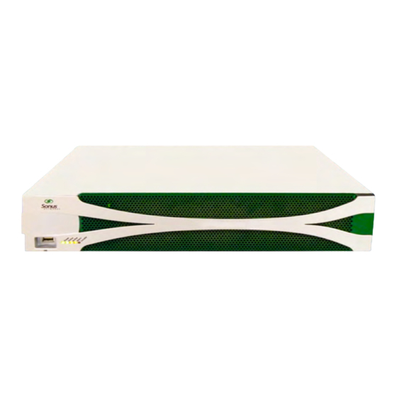
Platform. FIGURE 1–1 SBC 5200 Platform Front View FIGURE 1–2 SBC 5200 Platform Rear View 1–2 550-02545 — Beta Version 1 — Release V03.00.00 © 2012 Sonus Networks, Inc. Confidential and Proprietary. All Rights Reserved. Do not distribute without permission. -
Page 15: Chassis
The chassis must be installed in adherence with the environmental specifications and power source requirements listed in the appendix "Site Preparation Checklist" on page A–1. 550-02545 — Beta Version 1 — Release V03.00.00 1–3 © 2012 Sonus Networks, Inc. Confidential and Proprietary. All Rights Reserved. Do not distribute without permission. -
Page 16: Safety And Regulatory Information
The SBC 5200 complies with the following EMC and Immunity standards: • 47 CFR 15B Class A 1–4 550-02545 — Beta Version 1 — Release V03.00.00 © 2012 Sonus Networks, Inc. Confidential and Proprietary. All Rights Reserved. Do not distribute without permission. -
Page 17: Environmental Standards
System Requirements: Physical Protection) and GR-1089- CORE (Electromagnetic Compatibility and Electrical Safety - Generic Criteria for Network Telecommunications Equipment). 550-02545 — Beta Version 1 — Release V03.00.00 1–5 © 2012 Sonus Networks, Inc. Confidential and Proprietary. All Rights Reserved. Do not distribute without permission. -
Page 18: Site Planning And Requirements
15 days in a year. Non-operating Up to 93% non-condensing 100.4°F (37.7°C) maximum wet bulb. 1–6 550-02545 — Beta Version 1 — Release V03.00.00 © 2012 Sonus Networks, Inc. Confidential and Proprietary. All Rights Reserved. Do not distribute without permission. - Page 19 0.1G (x,y axis); 0.15G (z axis), 5-500Hz, 1 Oct/min Non-operating 5-20 Hz 0.01 g /Hz and 20-200 Hz - 3dB/octave 550-02545 — Beta Version 1 — Release V03.00.00 1–7 © 2012 Sonus Networks, Inc. Confidential and Proprietary. All Rights Reserved. Do not distribute without permission.
-
Page 20: Site Power Requirements
Bonded to a grounding system utilizing either an Isolated Bonding Network (Isolated Ground) or a Common Bonding Network (Integrated Ground). 1–8 550-02545 — Beta Version 1 — Release V03.00.00 © 2012 Sonus Networks, Inc. Confidential and Proprietary. All Rights Reserved. Do not distribute without permission. -
Page 21: Customer Replaceable Units
Used to secure the replaceable air filter and displays LED status on the front of the chassis. 550-02545 — Beta Version 1 — Release V03.00.00 1–9 © 2012 Sonus Networks, Inc. Confidential and Proprietary. All Rights Reserved. Do not distribute without permission. -
Page 22: Field Replaceable Units Hard Drives
Located within the SBC 5200 Platform chassis and Cards used to support transcoding. NOTE Requires authorized service personnel for removal or replacement. 1–10 550-02545 — Beta Version 1 — Release V03.00.00 © 2012 Sonus Networks, Inc. Confidential and Proprietary. All Rights Reserved. Do not distribute without permission. -
Page 23: Network Ports And Connections
LEDs are On during a reset. The front panel LEDs are as depicted in Figure 1–3. FIGURE 1–3 Front panel layout and LEDs 550-02545 — Beta Version 1 — Release V03.00.00 1–11 © 2012 Sonus Networks, Inc. Confidential and Proprietary. All Rights Reserved. Do not distribute without permission. -
Page 24: Rear Panel
LEDs is On during a reset. The rear panel layout and LEDs are as depicted in Figure 1–4. 1–12 550-02545 — Beta Version 1 — Release V03.00.00 © 2012 Sonus Networks, Inc. Confidential and Proprietary. All Rights Reserved. Do not distribute without permission. - Page 25 An RS-232 port used by BMC and Control Plane. The Serial Port uses a DB9 connector accessible from the rear panel. 550-02545 — Beta Version 1 — Release V03.00.00 1–13 © 2012 Sonus Networks, Inc. Confidential and Proprietary. All Rights Reserved. Do not distribute without permission.
- Page 26 Checks if the link and activity is present. • Green = Link • Flashing = Activity 1–14 550-02545 — Beta Version 1 — Release V03.00.00 © 2012 Sonus Networks, Inc. Confidential and Proprietary. All Rights Reserved. Do not distribute without permission.
-
Page 27: Overview
Hardware Installation Procedure CHAPTER 2 Overview This chapter provides the SBC 5200 hardware tasks to perform prior to software installation. Before proceeding further, verify if all the requirements listed in Chapter 1, "Hardware Installation Overview" are met. Topics include: •... -
Page 28: Quickstart Installation Of The Sbc 5200 Platform
Establish connections to the SBC 5200 Platform. For more information, refer "Establishing Connections to the SBC 5200 Platform" on page 2–29. 2–2 550-02545 — Beta Version 1 — Release V03.00.00 © 2012 Sonus Networks, Inc. Confidential and Proprietary. All Rights Reserved. Do not distribute without permission. -
Page 29: Unpacking The Container
#10-32X5/16" flathead screws - 4 • #10-32 U-Nuts - 8 FIGURE 2–1 19" 4 Post Slide Rack Kit 550-02545 — Beta Version 1 — Release V03.00.00 2–3 © 2012 Sonus Networks, Inc. Confidential and Proprietary. All Rights Reserved. Do not distribute without permission. -
Page 30: 23" Rack Adaptor Kit
#10-32X5/16" flathead screws - 4 • #10-32-5/8" Cuphead screws - 12 • #10-32 U-Nuts - 12 2–4 550-02545 — Beta Version 1 — Release V03.00.00 © 2012 Sonus Networks, Inc. Confidential and Proprietary. All Rights Reserved. Do not distribute without permission. - Page 31 Hardware Installation Guide Unpacking the Container Hardware Installation Procedure FIGURE 2–3 19" 2 Post Slide Rack Kit 550-02545 — Beta Version 1 — Release V03.00.00 2–5 © 2012 Sonus Networks, Inc. Confidential and Proprietary. All Rights Reserved. Do not distribute without permission.
-
Page 32: Chassis And Rack Preparation
Chassis Rails and the Chassis Rack Ears. FIGURE 2–4 Attaching Chassis Rails and Chassis Rack Ears 2–6 550-02545 — Beta Version 1 — Release V03.00.00 © 2012 Sonus Networks, Inc. Confidential and Proprietary. All Rights Reserved. Do not distribute without permission. -
Page 33: Marking The Racks
It is recommended to install the system at the lowest available space in the rack. FIGURE 2–5 Rack Markings 550-02545 — Beta Version 1 — Release V03.00.00 2–7 © 2012 Sonus Networks, Inc. Confidential and Proprietary. All Rights Reserved. Do not distribute without permission. -
Page 34: Rack-Mounting The Chassis
Push the Chassis fully into Rack Rail Guides, until the Chassis Rack Ears are in full contact with the front surface of Rack Rail Guides. 2–8 550-02545 — Beta Version 1 — Release V03.00.00 © 2012 Sonus Networks, Inc. Confidential and Proprietary. All Rights Reserved. Do not distribute without permission. -
Page 35: 23-Inch 4 Post Rack
550-02545 — Beta Version 1 — Release V03.00.00 2–9 © 2012 Sonus Networks, Inc. Confidential and Proprietary. All Rights Reserved. Do not distribute without permission. -
Page 36: Installing Chassis Into The Slide Rack Assembly
Tighten the (4) #10-32 X5/8" Cuphead screws securing the Rack Rail Guides to the Rack Adaptors. 2–10 550-02545 — Beta Version 1 — Release V03.00.00 © 2012 Sonus Networks, Inc. Confidential and Proprietary. All Rights Reserved. Do not distribute without permission. -
Page 37: 19-Inch 2 Post Rack
Rack Mount Brackets and secure with (4) #8-32X5/16" Panhead screws, repeat the same procedure for the opposite side. 550-02545 — Beta Version 1 — Release V03.00.00 2–11 © 2012 Sonus Networks, Inc. Confidential and Proprietary. All Rights Reserved. Do not distribute without permission. -
Page 38: 23 Inch 2 Post Rack
(2) #10-32X5/8" Cuphead screws at the top-most and at the bottom-most racking slots. 2–12 550-02545 — Beta Version 1 — Release V03.00.00 © 2012 Sonus Networks, Inc. Confidential and Proprietary. All Rights Reserved. Do not distribute without permission. -
Page 39: Installing Rack Mount Brackets
Fully tighten the (4) #10-32 X5/8" Cuphead screws securing the Rack Rail Guides to the Rack Adaptors. 550-02545 — Beta Version 1 — Release V03.00.00 2–13 © 2012 Sonus Networks, Inc. Confidential and Proprietary. All Rights Reserved. Do not distribute without permission. -
Page 40: Chassis Removal
Chassis Release Latch which needs to be pressed on both sides to release the chassis. 2–14 550-02545 — Beta Version 1 — Release V03.00.00 © 2012 Sonus Networks, Inc. Confidential and Proprietary. All Rights Reserved. Do not distribute without permission. -
Page 41: Attaching Wrist Straps
The ESD grounding chassis can be on the rack or the chassis as per the customer requirement. 550-02545 — Beta Version 1 — Release V03.00.00 2–15 © 2012 Sonus Networks, Inc. Confidential and Proprietary. All Rights Reserved. Do not distribute without permission. -
Page 42: Attaching The Front Bezel
Attaching the Front Bezel After the SBC 5200 Platform is rack mounted, you must attach the front bezel to the SBC 5200 Platform by aligning 4 ball studs located on the bezel assembly to the ball stud sockets located on the SBC 5200 Platform chassis. Apply equal forward pressure to the four corners of the bezel assembly until each of the four corners “click-in”. -
Page 43: Port Connections
Replace the SFP modules to resolve issue. Serial Port Connections To establish the serial connection, you must connect the supplied cable PN 401- 00119 to the Serial port of the SBC 5200 Platform and Serial port of the host PC, refer to Figure 2–12. -
Page 44: Management Port Connections
2 input alarms. You must create the remainder of the cable, wiring the appropriate sensor or alarm leads to the screw terminator on the connector. 2–18 550-02545 — Beta Version 1 — Release V03.00.00 © 2012 Sonus Networks, Inc. Confidential and Proprietary. All Rights Reserved. Do not distribute without permission. - Page 45 Major Alarm Normally Open Major Alarm Normally Closed Major Alarm Return Power Alarm Normally Open Power Alarm Return 550-02545 — Beta Version 1 — Release V03.00.00 2–19 © 2012 Sonus Networks, Inc. Confidential and Proprietary. All Rights Reserved. Do not distribute without permission.
-
Page 46: Alarm Out Ports
DC maximum across an external load.) NOTE Pin 1 is beside the Alarm In text on the module face plate. 2–20 550-02545 — Beta Version 1 — Release V03.00.00 © 2012 Sonus Networks, Inc. Confidential and Proprietary. All Rights Reserved. Do not distribute without permission. -
Page 47: Setting Up Physical Connection Between High Availability Nodes
For the media ports, the MAC and IP addresses do float (are replicated from active to standby on failover). FIGURE 2–14 HA Port connection 550-02545 — Beta Version 1 — Release V03.00.00 2–21 © 2012 Sonus Networks, Inc. Confidential and Proprietary. All Rights Reserved. Do not distribute without permission. - Page 48 SX modules must be attached at both sides of the HA port, HA connection will not work if LX module is at one side. 2–22 550-02545 — Beta Version 1 — Release V03.00.00 © 2012 Sonus Networks, Inc. Confidential and Proprietary. All Rights Reserved. Do not distribute without permission.
-
Page 49: Connecting To Power And Powering On The Switch
After installing the SBC 5200 Platform to a rack and installing the necessary cables, you are now ready to apply power to the switch. The SBC 5200 Platform is equipped with dual redundant AC or DC Power. Before connecting to power, you must connect the Chassis ground lug. -
Page 50: Connecting To Ac Power And Powering On
The following procedure explains how to connect to the AC power and powering on the switch: Connecting to AC Power and Powering On Insert the end of the power cords to the SBC 5200 Platform at the rear of the chassis as shown in Figure 2–16. -
Page 51: Disconnecting From Ac Power Source
Disconnecting from AC Power Source Turn off your local AC power source. Remove the power cord. End of Procedure 550-02545 — Beta Version 1 — Release V03.00.00 2–25 © 2012 Sonus Networks, Inc. Confidential and Proprietary. All Rights Reserved. Do not distribute without permission. -
Page 52: Connecting To Dc Power And Powering On
Do not apply DC power to the DC Power supply and then hot-insert the supply into the chassis. 2–26 550-02545 — Beta Version 1 — Release V03.00.00 © 2012 Sonus Networks, Inc. Confidential and Proprietary. All Rights Reserved. Do not distribute without permission. -
Page 53: Disconnecting From Dc Power Source
Do not remove the DC Power supply without first turning off the power to the unit being removed from the chassis. 550-02545 — Beta Version 1 — Release V03.00.00 2–27 © 2012 Sonus Networks, Inc. Confidential and Proprietary. All Rights Reserved. Do not distribute without permission. -
Page 54: Removing Power Supply
Figure 2–18 Figure 2–19. FIGURE 2–18 Removing DC Power Supply FIGURE 2–19 Removing AC Power Supply 2–28 550-02545 — Beta Version 1 — Release V03.00.00 © 2012 Sonus Networks, Inc. Confidential and Proprietary. All Rights Reserved. Do not distribute without permission. -
Page 55: Establishing Connections To The Sbc 5200 Platform
The BMC runs its own embedded Operating System and can be accessed via a serial port on the rear of the SBC 5200 Platform or via a dedicated Ethernet port, thus providing out-of-band management capability. Using the BMC, you can remotely manage the SBC 5200 Platform as if you were using a locally attached console terminal. - Page 56 Hardware Installation Guide Hardware Installation Procedure 2–30 550-02545 — Beta Version 1 — Release V03.00.00 © 2012 Sonus Networks, Inc. Confidential and Proprietary. All Rights Reserved. Do not distribute without permission.
- Page 57 Overview This appendix provides a checklist of the tasks to be performed to prepare a site for the SBC 5200 installation. Also, it includes a post-installation checklist. For specific information on the site evaluation parameters, refer to "Site Planning and Requirements"...
-
Page 58: Pre-Installation Checklist
Distance to Power source/Grounding sources Distance to data ports (routers/Switches) Console/FSP access requirements IP addressing schema A–2 550-02545 — Beta Version 1 — Release V03.00.00 © 2012 Sonus Networks, Inc. Confidential and Proprietary. All Rights Reserved. Do not distribute without permission. -
Page 59: Post Installation Checklist
550-02545 — Beta Version 1 — Release V03.00.00 A–3 © 2012 Sonus Networks, Inc. Confidential and Proprietary. All Rights Reserved. Do not distribute without permission. - Page 60 Hardware Installation Guide Post Installation Checklist A–4 550-02545 — Beta Version 1 — Release V03.00.00 © 2012 Sonus Networks, Inc. Confidential and Proprietary. All Rights Reserved. Do not distribute without permission.
Need help?
Do you have a question about the 5200 and is the answer not in the manual?
Questions and answers