
Subscribe to Our Youtube Channel
Related Manuals for FIBARO FGT-001


Summary of Contents for FIBARO FGT-001
-
Page 1: Table Of Contents
O P E R A T I N G M A N U A L THE HEAT CONTROLLER RADIATOR THERMOSTAT FGT-001 CONTENTS v1.0 #1: Description and features #12: Factory reset #2: Basic activation #13: Z-Wave range test #3: Adding to Z-Wave network... -
Page 2: Important Safety Information
Do not attempt to replace the battery! General information about the FIBARO System FIBARO is a wireless smart home automation system, based on the Z-Wave protocol. All of available devices can be controlled through a computer (PC or Mac), smartphone or tablet. Z-Wave devices are not only receivers, but can also repeat the signal, increasing the Z-Wave network’s range. -
Page 3: 1: Description And Features
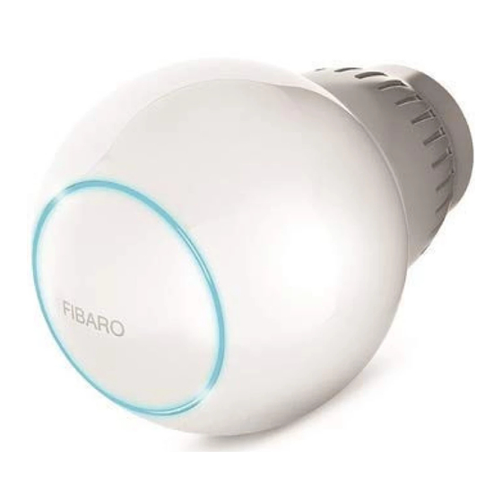
#1: Description and features FIBARO Heat Controller is a remotely controlled thermostatic head to control temperature in your room. It measures the temperature and automatically adjust the heat level. It can be mounted without tools on three types of thermostatic radiator valves. -
Page 4: 2: Basic Activation
#2: Basic activation 1. Connect the charger to the micro-uSB port to charge the device. If you have the temperature sensor: a. use a coin to open the battery cover by turning it coun- ter-clockwise. b. Remove the sticker underneath the battery. c. -
Page 5: 3: Adding To Z-Wave Network
#3: Adding to Z-Wave network Adding (Inclusion) - Z-Wave device learning mode, allowing to add the device to existing Z-Wave network. To add the device to the Z-Wave network: 1. Make sure the device is within the direct range of your Z-Wave controller. -
Page 6: 4: Removing The Device
#4: Removing the device Removing (Exclusion) - Z-Wave device learning mode, allowing to NOTE remove the device from existing Z-Wave network. Removing the device To remove the device from the Z-Wave network: from the Z-Wave net- work restores all the 1. -
Page 7: 5: Controlling The Temperature
#5: Controlling the temperature You can set temperature using app (10-30°C) or directly on the device (16-24°C). During manual temperature change LED ring colour corresponds to the temperature set-point. To check and change the temperature on the device: 1. Bring your hand close to the sphere. 2. -
Page 8: 6: Extra Temperature Sensor
#6: Extra temperature sensor The device can be used with an additional, dedicated temperature NOTE sensor (FGBRS-001) to provide the best temperature regulation. FGBRS-001 is the only It can be placed anywhere in the room and the device will use it as a compatible tempera- reference point for the room temperature. -
Page 9: 7: Dismounting The Device
#7: Dismounting the device Before dismounting, the device must be put in Standby Mode to ensure safe removal. See chapter „Standby Mode” on page 13 for more information. To dismount the device: 1. use the included key to press and hold the button. 2. -
Page 10: 8: Menu
#8: Menu Menu allows to perform important configuration and maintenance actions. In order to use the menu: 1. use the included key to press and hold the button. 2. Release the button when you see desired LED colour: Colour Action Blue pair dedicated temperature sensor enable/disable local control protec-... -
Page 11: 9: Local Protection
#9: Local protection After enabling the local protection changing temperature directly on the device (by turning it) will not be possible. Enabling local protection is recommended if you want to prevent ac- cidental temperature change, e.g. by children. When attempting to change temperature if local protection is enabled: •... -
Page 12: 10: Head Calibration
#10: Head calibration Calibrating the device to your radiator valve is required for proper NOTE controlling the temperature. Calibration cannot be performed while the device is being Calibration is performed: charged. • Automatically, after 10 minutes from turning on if no operation on the device has been made (only at first installation), •... -
Page 13: 11: Standby Mode
#11: Standby Mode In Standby Mode the device is in deep sleep state allowing safe dis- mounting, transporting and low as possible battery consumption. The device is shipped in Standby Mode. Entering the device in Standby Mode will not factory reset the device nor will result in loosing any data. -
Page 14: 12: Factory Reset
#12: Factory reset Reset procedure allows to restore the device back to its factory set- NOTE tings, which means all information about the network and user con- Resetting the device is figuration will be deleted. not the recommend- ed way of removing the device from the To perform factory reset: Z-Wave network. -
Page 15: 13: Z-Wave Range Test
#13: Z-Wave range test The device has a built in Z-Wave network main controller’s range tester. To perform range test: 1. use the included key to press and hold the button. 2. Release the button when you see magenta LED colour. 3. -
Page 16: 14: Battery And Charging
#14: Battery and charging The device is equipped with a rechargeable lithium-polymer bat- CAUTION tery pack that can be charged via micro-uSB port using standard 5v Make sure you are using charger (not included). certified charger Class When battery is low the LED ring will start to blink red. The device II, marked which will also report low battery status of itself and dedicated temperature... -
Page 17: 15: Normal Schedules
#15: Normal Schedules The device allows to create multiple heating schedules to manage temperature in the room throughout the week. Schedules are created via controller interface or app. • up to 253 normal schedules can be created. • The lower the schedule ID number, the higher the priority. •... -
Page 18: 16: Override Schedule
#16: Override Schedule Override Schedule is a special type schedule that has the highest priority; thus it overrides other schedules. The Override Schedule starts right after setting and lasts for specified time, then it is removed and current schedule or normal operation is restored. -
Page 19: 17: Z-Wave Specification
#17: Z-Wave specification Endpoint 1: Generic Device Class: GENERIC_TYPE_THERMOSTAT Specific Device Class: SPECIFIC_TYPE_THERMOSTAT_GENERAL_v2 Description: represents thermostatic head, allows to set tempera- ture, schedules and check its battery level. Endpoint 2: Generic Device Class: GENERIC_TYPE_SENSOR_MuLTILEvEL Specific Device Class: SPECIFIC_TYPE_ROuTING_SENSOR_MuLTILEvEL Description: represents dedicated temperature sensor, allows to check temperature and its battery level (if not paired reported tem- perature and battery level are always 0). - Page 20 Supported Command Classes: Command Class version Secure ZWAvEPLuS_INFO [0x5E] ASSOCIATION [0x85] MuLTI_CHANNEL_ASSOCIATION [0x8E] BASIC [0x20] APPLICATION_STATuS [0x22] THERMOSTAT_MODE [0x40] THERMOSTAT_SETPOINT [0x43] SCHEDuLE [0x53] TRANSPORT_SERvICE [0x55] ASSOCIATION_GRP_INFO [0x59] DEvICE_RESET_LOCALLY [0x5A] MuLTI_CHANNEL [0x60] SuPERvISION [0x6C] NOTIFICATION [0x71] MANuFACTuRER_SPECIFIC [0x72] POWERLEvEL [0x73] PROTECTION [0x75] FIRMWARE_uPDATE_MD [0x7A] BATTERY [0x80] CLOCk [0x81]...
- Page 21 Multichannel Command Class: Command Class version Secure Endpoint 1 ZWAvEPLuS_INFO [0x5E] ASSOCIATION [0x85] MuLTI_CHANNEL_ASSOCIATION [0x8E] BASIC [0x20] THERMOSTAT_MODE [0x40] THERMOSTAT_SETPOINT [0x43] SCHEDuLE [0x53] ASSOCIATION_GRP_INFO [0x59] SuPERvISION [0x6C] NOTIFICATION [0x71] BATTERY [0x80] CLOCk [0x81] PROTECTION [0x75] SECuRITY [0x98] SECuRITY_2 [0x9F] Endpoint 2 ZWAvEPLuS_INFO [0x5E] ASSOCIATION [0x85] MuLTI_CHANNEL_ASSOCIATION [0x8E]...
- Page 22 Notification Command Class: The device uses Notification Command Class to report different events to the controller (“Lifeline” group). Endpoint 1: Notification Event Event Parameters Type Charge battery soon [0x0E] Power Charge battery now! [0x0F] Management Battery is charging [0x0C] [0x08] Battery is fully charged [0x0D] External sensor remove [0x02]...
-
Page 23: 18: Advanced Parameters
#18: Advanced parameters The device allows to customize its operation to user’s needs. The set- NOTE tings are available in the FIBARO interface as simple options that may be chosen by selecting the appropriate box. Entering invalid value of parameter will re-... -
Page 24: 19: Specifications
#19: Specifications Power supply: 3.7v Li-Poly battery pack (non-re- placeable) NOTE Charging port: micro-uSB Charger type: unit shall be supplied by a source Charger voltage (not included): 5v DC (±5%) certified as Limited Power Source (LPS) as Minimum charger current 0.5A defined in clause 2.5 (not included):... - Page 25 For communication with the controller: Radio protocol: Z-Wave (500 series chip) Radio frequency band: 868 MHz ISM band (for Eu) Maximum transmit power: EIRP up to -4dBm For communication with the extra sensor (FGBRS-001): Radio frequency band: 2.4 GHz ISM band Maximum transmit power: EIRP up to 6dBm SPECIFICATIONS...
-
Page 26: 20: Accessory Specification (Fgbrs-001)
#20: Accessory specification (FGBRS-001) Power supply: CR2032, 3.0v battery (included) CAUTION using batteries other Operating temperature: 0–40°C than specified may re- sult in explosion. Dis- Storage temperature: -10–40°C pose of properly, ob- serving environmental Temperature measuring accu- 0.5°C (within 0–40°C range) protection rules. -
Page 27: 21: Regulations
All information, including, but not limited to, information regarding the features, functionality, and/or other product specification are subject to change without notice. Fibaro reserves all rights to revise or update its products, software, or documentation without any obligation to no- tify any individual or entity.
Need help?
Do you have a question about the FGT-001 and is the answer not in the manual?
Questions and answers