Table of Contents
Advertisement
Quick Links
Advertisement
Table of Contents

Related Manuals for Rackable Systems OmniStor 4000S Series


Summary of Contents for Rackable Systems OmniStor 4000S Series
- Page 3 Rackable Systems Inc. Rackable Systems Inc. shall not be liable for any damages or for the loss of any information resulting from the performance or use of the information contained herein.
-
Page 5: Table Of Contents
Contents About this Manual ................Welcome .......................... v Features ........................... vi 1 Getting Started..................1 At a Glance........................2 Components........................3 Front Bezel........................3 Power System......................4 Standard AC Hot Swappable Power Supplies............4 Optional DC Hot Swappable Power Supplies............5 Cooling Fan Module.................... - Page 6 Cabling the DC Power Supplies..............29 Before You Continue..................31 Special Note for Microsoft Windows 2000/2003 Installations......31 Operating Mode Configuration and Cabling............32 JBOD - 12 Drive Configuration..............32 JBOD - 24 Drive Configuration..............37 Topology Host Cabling..................40 Single Bus Clustering Configuration............
- Page 7 Contents Warning and Error Events....................70 Warnings........................70 Errors.......................... 70 Disk Errors........................... 71 6 Maintenance..................74 Removing the Front Bezel....................74 Replacing the Cooling Fans....................76 Replacing an AC Power Supply..................78 Replacing a DC Power Supply..................80 Replacing a Disk Drive..................... 82 Replacing the SAF-TE Disk I/O or SCSI SAF-TE............
-
Page 9: About This Manual
About this Manual Welcome Congratulations on the purchase of your new OmniStor 4000S Series JBOD Storage System from Rackable Systems. The OmniStor 4000S Series is a very high-performance fully fault-tolerant Ultra320/160 SCSI storage system. Its unique 2U design is optimized to fit in the compact space of today’s data center rack enclosures and as a deskside tower... -
Page 10: Features
About this Manual Features The OmniStor 4000S Series Storage Systems is designed for mission critical applications requiring the highest performance with uncompromised data reliability, such as mid-range and enterprise server storage. They maintain exceptionally high throughput and are ideally suited for high bandwidth data intensive applications, such as electronic commerce, digital video, CAD, seismic research, digital pre-press, and 3-D imaging. -
Page 11: Getting Started
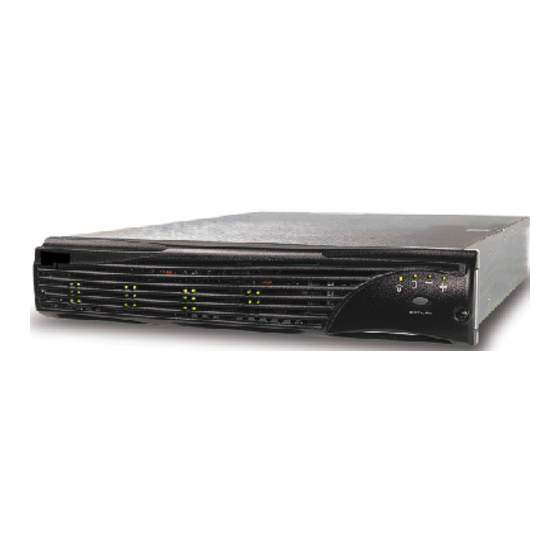
The Components section identifies and gives a complete description of each major component. The Monitoring section describes the enclosure’s LEDs, and the manner in which the normal and abnormal conditions are presented. Rack-Mount Model Tower Model OmniStor 4000S Series Storage System... -
Page 12: At A Glance
Chapter 1 - Getting Started At a Glance The following illustrations show the featured components of the OmniStor 4000S Series Storage System. Familiarize yourself with its components prior to installing and using the storage system. 350-watt hot pluggable independent power... -
Page 13: Components
Chapter 1 - Getting Started Components This section provides a descriptive overview of each of the major components that comprise the OmniStor 4000S Series Storage System. Front Bezel The front bezel houses the Status LEDs, Drive LEDs, and alarm reset button. When removed, the user has access to the disk drives. -
Page 14: Power System
Chapter 1 - Getting Started Power System Standard AC Hot Swappable Power Supplies The AC power system consists of two 350-watt hot-pluggable power supplies, each with independent AC power cords and cooling fans. This power system provides the enclosure with “N+1” redundant power. Each power supply has auto-switching circuitry for use with either 100V or 240V AC systems. -
Page 15: Optional Dc Hot Swappable Power Supplies
Chapter 1 - Getting Started Optional DC Hot Swappable Power Supplies The DC power system is designed to allow the storage system to be installed with Telco system hardware isntallations. It consists of two 350-watt hot-pluggable power supplies, each with independent DC power cables and cooling fans. It provides the enclosure with “N+1” redundant power with Telco hardware. -
Page 16: Cooling Fan Module
Chapter 1 - Getting Started The power feed must be electrically isolated from any AC power source, provide a reliable connection to earth (battery room positive bus is connected to the grounding electrode), and capable of providing up to 600 watts of continuous power per feed pair. Overcurrent Protection Requirements Overcurrent protection devices must be provided as part of each equipment rack. -
Page 17: Cooling Fan Module
Chapter 1 - Getting Started If any one fan should fail, cooling redundancy and efficiency are degraded. The cooling fans and enclosure temperature are constantly monitored by the SAF-TE processor for fault conditions. In the event of a fault condition the front panel Fan Status LED will change from a green state to a solid amber state in the case of a fan failure, or to a blinking amber green state in the case of an over-temperature condition. -
Page 18: Saf-Te Disk I/O Card
Chapter 1 - Getting Started The SAF-TE Disk I/O card has a firmware-based VT-100 interface which provides an option to manage fan speed. This option provides a whisper mode fan operation for noise sensitive environments. When enabled (default), and based on a set of conditions, the software will manage the cooling fans RPM speed to maintain the enclosure temperature while minimizing noise levels. - Page 19 Chapter 1 - Getting Started At power up, the SAF-TE processors read the SCSI switch settings and configures the system for the appropriate addresses. It then executes instructions from firmware performing a self-test diagnostics. The firmware is flash upgradeable using the SAF-TE RS-232 Service port located below the I/O card slots at the rear of the enclosure.
-
Page 20: Scsi Saf-Te Cluster Card
Chapter 1 - Getting Started at the end of the chain. Those enclosures will need to have their jumper settings, JP7 and JP8, set to the jumpered position. During installation setup, instructions are provided to correctly configure the daisy-chain enclosure settings. These jumpers enable and disable the automatic termination. -
Page 21: Spin-Up Settings
Chapter 1 - Getting Started The use of the Ultra320 bus expanders allows the full support of clustering environments where a system can be removed in a live environment without bringing down the bus, therefore ensuring an ideal solution for high availability clustering systems. The SCSI SAF-TE Cluster card has two SAF-TE processors (SEPs) that continuously monitor the enclosure for temperature status, fan status, power supply status, and SCSI channel status. -
Page 22: Single Bus Module
Chapter 1 - Getting Started “DL” Switch 7 “RM” Switch 8 Drive Spin-up Mode Down (0)* Down (0)* Drive motor spins up at DC power on. Down (0) Up (1) Drive motor spins up only on SCSI “start” commands. Up (1) Down (0) Drive motor spins up after a delay of 12 (may vary depending on drive type) seconds times the... - Page 23 Chapter 1 - Getting Started Single Bus Module Single-Bus Module Cover Plate Installing the Single Bus Module and Cover Plate Single Bus Module...
-
Page 24: Rs-232 Service Ports
Chapter 1 - Getting Started RS-232 Service Ports Located below the I/O card slots is the SAF-TE service port and two RAID Controller service ports. Refer to the illustration under “At a Glance” for the port locations on the rear panel. Controller 1: Service Port SAF-TE Service Port Controller 2: Service Port... -
Page 25: Control And Monitoring
Chapter 1 - Getting Started Control and Monitoring An integral part of the OmniStor 4000S Series Storage System is its control and monitor capabilities. The SAF-TE processors provide monitoring data for the enclosure environmental conditions such as enclosure temperature, cooling fans, power supplies, and SCSI bus status. -
Page 26: Power-On Led
Chapter 1 - Getting Started Power-On LED The Power-On LED signifies that the enclosure is powered on and will be illuminated green when power has been applied. Channel Status LED The Channel Status LED will remain green at all times when the enclosure is setup in JBOD mode. -
Page 27: Theory Of Controller Operation
This chapter provides a functional overview and understanding of the supported topologies and operating modes for the OmniStor 4000S Series Storage System. With this information, you will be able to make the best choice based on the supported topologies, to set up your storage solution. -
Page 28: A Word About Clustering
Chapter 2 - Theory of Controller Operation A Word about Clustering Minimizing Downtime for Maximum Data Availability So-called open systems, such as Windows NT servers, just don’t provide the level of availability that IS managers are familiar with on mainframes. A partial solution to this problem is server clustering. - Page 29 Chapter 2 - Theory of Controller Operation from one node to two nodes. Going from one node to a four node cluster generally yields a 2.5x or 3x performance boost. However, the cluster performance is application dependent. For example, READ operations may yield a 1.8x performance increase going from one to two nodes, but in a WRITE intensive application, you may only see a 1.4-1.6x improvement.
- Page 30 Chapter 2 - Theory of Controller Operation Minimizing Downtime for Maximum Data Availability...
-
Page 31: Setup And Installation
Chapter 3 Setup and Installation Overview This chapter describes the procedures to install and setup the OmniStor 4000S Series Storage System. Each section will step you through the hardware installation, cabling and topology configurations, and upgrades. It is important to thoroughly review this information and perform the steps of procedures in each applicable section, in the order in which they are presented. -
Page 32: Storage System Detailed Installation
Chapter 3 - Setup and Installation Storage System Detailed Installation This section describes preparing and installing the enclosure(s) into the rack cabinet or the enclosure into its tower stand (refer to “Installing the Storage System into the Tower Stand” on page 25). After installing the hardware components, go to the “Operating Mode Configuration and Cabling”... - Page 33 Chapter 3 - Setup and Installation Locate the mounting rails and mounting hardware in the accessory kit (some installations require cage nuts and others use standard nuts). NOTE: It will be helpful to have an assistant available during the installation. Install the rear mounting rails.
- Page 34 Chapter 3 - Setup and Installation Front Rack Vertical Member Mounting Screw Mounting Chassis Ear Screw Attaching the Chassis Ears Re-install the power supplies. Slide each power supply into its empty bay and ensure it seats completely, and that the release latch resets.
-
Page 35: Installing The Storage System Into The Tower Stand
Chapter 3 - Setup and Installation Installing the Storage System into the Tower Stand Remove the storage system from its shipping carton and inspect for obvious damage. Remove and open the accessory kit, and remove the contents. Open the left and right flaps, and remove the bezel and mounting rails. - Page 36 Chapter 3 - Setup and Installation Inserting and Securing the Chassis 11 Re-install the cooling fan module. Slide it into its open bay and ensure it seats completely, and the release latch resets. Installing the Storage System into the Tower Stand...
-
Page 37: Completing The Installation
Chapter 3 - Setup and Installation 12 Re-install the power supplies. Slide each power supply into its open bay and ensure it seats completely, and the release latch resets. 13 Continue now with “Completing the Installation” on page 27. Completing the Installation Install the disk drives. - Page 38 Chapter 3 - Setup and Installation Secure the front bezel using a Phillips screwdriver by rotating the fasteners clockwise one-quarter turn. Attaching the Front Bezel (Rack and Tower Models) CAUTION: Verify that the power supply On/Off switches are in their OFF position. (AC Power Supplies Only) Install the power cords and secure them using the power cord bales.
-
Page 39: Cabling The Dc Power Supplies
Chapter 3 - Setup and Installation Bale fits over and onto the power cord. Attaching the Power Cord Bales Connect the other end of the power cord into a three-hole grounded outlet or UPS power system. A UPS is highly recommended. Repeat steps 2(a) and 2(b) for the other power cord. - Page 40 Chapter 3 - Setup and Installation Attaching the DC Cable Repeat the above steps (1 - 4) for the second power supply, if this option was ordered. This completes the physical hardware installation. Cabling the DC Power Supplies...
-
Page 41: Before You Continue
Chapter 3 - Setup and Installation Before You Continue... The next section, Enclosure Configuration, includes steps and diagrams for setting the SAF-TE Disk I/O card/SCSI SAF-TE Cluster card switches and attaching the required SCSI data cables for each drive configuration. Locate the applicable configuration and refer to the steps and diagrams to set the card switches and cable your system. -
Page 42: Operating Mode Configuration And Cabling
Chapter 3 - Setup and Installation Operating Mode Configuration and Cabling In this section, configurations are determined by the enclosure model type (JBOD – OmniStor 4000S), SCSI bus configuration, number of enclosures and the available number of drives. Follow the steps of procedure for your configuration to set the switches, jumpers, and connect the SCSI data cables. - Page 43 Chapter 3 - Setup and Installation In Dual-Bus Mode, the Channel 1 connector on the SAF-TE Disk I/O card provides access to drives 1 through 6 and the Channel 2 connector provides access to drives 7 through 12. NOTE: In the preceding logical view diagrams, the drive slots are used to indicate which drives are connected to which channel.
- Page 44 Chapter 3 - Setup and Installation SAF-TE ID = 15 Host ID (0 or 7) Single-Bus Mode Switch Settings Slot 1 Slot 4 Slot 7 Slot 10 ID 1 ID 9 ID 2 ID 10 Slot 2 Slot 5 Slot 8 Slot 11 ID 4 ID 12...
- Page 45 Chapter 3 - Setup and Installation (Single-Bus Mode Installations Only) Install the Single-Bus Module in the Controller 1 slot. Remove the Controller Cover plate. Loosen the four thumb screws and pull the cover plate from the enclosure. Single-Bus Module Cover Plate Single-Bus Module Installation Slide the Single-Bus Module in the Controller 1 (lower) slot, and secure it by pressing the latches into place.
- Page 46 Chapter 3 - Setup and Installation Cabling Diagrams JBOD Single Enclosure - Single-Bus Mode Cabling Diagrams JBOD Single Enclosure - Dual-Bus Mode This completes the OmniStor 4000S JBOD - 12 Drive Configuration setup, refer to “Powering On the Storage System” on page 44. Follow your operating system requirements for preparing new disk drives.
-
Page 47: Jbod - 24 Drive Configuration
Chapter 3 - Setup and Installation JBOD - 24 Drive Configuration The OmniStor 4000S can also be setup as a Single-Bus JBOD (Just a Bunch of Drives) configuration with two enclosure which will provide up to a 24 disk drive (12 per channel) storage solution. - Page 48 Chapter 3 - Setup and Installation Channel 1 Termination Jumper 1 2 3 4 5 6 7 8 DOWN Channel 2 Termination Jumper SAF-TE Disk I/O Card Switch and Jumper Locations There is one switch setting for both enclosures. SAF-TE ID = 15 Host ID (0 or 7) Single-Bus Mode Switch Settings...
- Page 49 Chapter 3 - Setup and Installation Connect a SCSI data cable from the host system HBA(s) to the SAF-TE Disk I/O card Channel 1 connectors on each enclosure. Cabling Diagram JBOD Dual Enclosures This completes the OmniStor 4000S JBOD - 24 Drive Configuration setup, refer to “Powering On the Storage System”...
-
Page 50: Topology Host Cabling
Chapter 3 - Setup and Installation Topology Host Cabling This section provides instructions for the physical cabling between the primary enclosure and your host system(s), and the cluster enclosure and your host system(s). Basic Connection Instructions Install your host bus adapter(s) into the host system(s). Refer to your HBA user’s guide for specific details. -
Page 51: Single Bus Clustering Configuration
Chapter 3 - Setup and Installation Single Bus Clustering Configuration The enclosure is setup as a Single-Bus configuration using a single enclosure which provides up to a 12 disk drive storage solution in a clustered environment. Logical View of Drive Connectivity - Single-Bus Mode In Single-Bus Mode access to the drives can occur through Channel 1 or Channel 2. - Page 52 Chapter 3 - Setup and Installation SCSI SAF-TE Clustering Card Switch and Jumper Locations There is one switch setting, refer to the switch setting illustration below and verify the switches are set as illustrated. Single-Bus Switch Setting Re-install the SCSI SAF-TE Clustering card. Slide the card into the slot and ensure that it seats completely.
- Page 53 Chapter 3 - Setup and Installation Connect the SCSI data cable(s) from the host system HBAs to the SCSI SAF-TE Clustering card. This completes the setup, refer to “Powering On the Storage System” on page 44. Follow your operating system requirements for preparing new disk drives. Single Bus Clustering Configuration...
-
Page 54: Powering On The Storage System
Chapter 3 - Setup and Installation Powering On the Storage System After you have the system setup and installed, you are ready to power on the storage system enclosure(s). NOTE: Ensure that none of the data cables or power cables are obstructing the air flow exiting the cooling fan module. -
Page 55: Monitoring Systems
Chapter 4 Monitoring Systems In this chapter you will find information about using the enclosure’s onboard monitoring systems. Also you will find procedures to update the enclosure’s SAF-TE Disk I/O/SCSI SAF-TE Cluster card firmware. Using a VT-100 terminal (or emulation), the SAF-TE RS-232 Service port provides an interface to the enclosure’s monitoring system and firmware. -
Page 56: Status Indicator Leds
Chapter 4- Monitoring Systems Status Indicator LEDs The Status Indicator LEDs located above the Alarm Reset button, comprise the Power-On LED, Channel Status LED, Power Supply Status LED, and Fan Status LED. The following are descriptions of each of the LEDs. Power-On LED The Power-On LED signifies that the enclosure is powered on and will be illuminated green when power has been applied. - Page 57 Chapter 4- Monitoring Systems The Drive Status LEDs comprise the “One-Touch Annunciation” monitoring system which can display the status of controllers and SAF-TE Disk I/O or SCSI SAF-TE Cluster card switch settings from the touch of the Alarm Reset button. Refer to “One-Touch Annunciation”...
-
Page 58: Drive Status Leds
Chapter 4- Monitoring Systems Fault LED LitePipes Activity LED Drive Carrier LitePipes Drive Status LEDs There are twelve Drive Status LEDs. The Drive Status LED is the left LED of each pair of Drive LEDs. This LED will illuminate steady green when a drive is present in the slot and powered on. -
Page 59: Led Matrix
Front Bezel LEDs These LEDs are located on the front bezel. Refer to the table below for a list of the LED conditions and their meaning: OmniStor 4000S Series Front Bezel LED Matrix Condition Drive Status LED At power up. - Page 60 Chapter 4- Monitoring Systems OmniStor 4000S Series Front Bezel LED Matrix Condition Drive Status LED POOL SPARE Blinking Green HOT SPARE Steady Amber Rebuild mode (All Drive Status LEDs) HOT SPARE READY Steady Green Assigned to an array. EMPTY DRIVE SLOT...
- Page 61 Chapter 4- Monitoring Systems One-Touch Annunciation The OmniStor 4000S “One-Touch Annunciation” monitoring system is an easily accessible press-to-touch display of the SAF-TE Disk I/O or SCSI SAF-TE Cluster card switch settings, enclosure bus mode, type of host interface, serial communication BAUD rate, and controller status using the Drive Status LEDs and the Alarm Reset button.
- Page 62 Chapter 4- Monitoring Systems The following are examples of the One-Touch Annunciation LEDs for switch settings, controller and bus configurations when the Alarm Reset button is pressed. JBOD Single-Bus Configuration Annunciation LED Sample NOTE: SAF-TE switches 1 (A0) and 2 (A1) work in combinations to create a specific range of SCSI IDs.
- Page 63 Chapter 4- Monitoring Systems Drive Slot Status LED Indication Condition Drive Slot 7 Switch 2 (A1) is in the DOWN position. This will set the Drive SCSI IDs of the slots to IDs 1, 2, 3, 4, 5, 6, 9, 10, 11, 12, 13, 14. It reserves IDs 0 and 7 for the host bus adapter, and SCSI ID 15 for the SAF-TE processor.
-
Page 64: One-Touch Annunciation
Chapter 4- Monitoring Systems Drive Slot Status LED Description Condition Drive Slot 1 Enclosure in dual-bus mode. Drive Slot 2 SCSI Host Interface. Drive Slot 3 Drive Slot 4 Switch 1 (A0) is in the DOWN position. This will set the Drive SCSI IDs of the slots to IDs 1, 2, 3, 4, 5, 6, 9, 10, 11, 12, 13, 14. -
Page 65: Enclosure Saf-Te Monitoring
Chapter 4- Monitoring Systems Enclosure SAF-TE Monitoring Another feature of the OmniStor 4000S Series storage system is the enclosure monitoring capabilities. The firmware-based monitoring program allows users to view storage system component status and information about the firmware. You may access this program by connecting a VT-100 terminal to the SAF-TE Service port. - Page 66 Chapter 4- Monitoring Systems At the screen cursor, type <Control-E>. The Enclosure Terminal Utility menu will appear. Enclosure Terminal Utility Screen To monitor the enclosure components, select option “1” Show Enclosure Environment Status by pressing the <1> key. The screen provides a status list of the internal components such as disk drives in a specific slot, temperature of the thermal sensors, cooling fan status, power supply status, and statistics on enclosure “up time.”...
-
Page 67: Uploading Saf-Te Disk I/O & Scsi Saf-Te Cluster Card Firmware
Chapter 4- Monitoring Systems Uploading SAF-TE Disk I/O & SCSI SAF-TE Cluster Card Firmware The following information describes the procedures to upload new firmware to the SAF-TE Disk I/O or SCSI SAF-TE Cluster card. The firmware can be uploaded in a “live” environment. - Page 68 Chapter 4- Monitoring Systems The Enclosure Terminal Utility menu will appear. Enclosure Terminal Utility Screen Select option “5” Firmware Upload by pressing the <5> key. Upload Firmware Screen Press the <u> key (lower case) to start the upload. Using the mouse, click on the pull-down menu Transfers and select “Send.”...
- Page 69 Chapter 4- Monitoring Systems Click the browse button and locate the new Firmware file and click “Send.” The firmware file will have a “.S3R” extension. NOTE: Ensure that the protocol “Xmodem” is selected. From the Xmodem send screen you can monitor the progress of the upload. You can safely stop the transfer without affecting your existing firmware any time during the transfer until it has been completed.
- Page 70 Chapter 4- Monitoring Systems A progress status screen will appear. At 100% the following screen will appear. Update Confirmation Screen After the confirmation is complete, the following screen will appear. Update Status Screen 10 Verify the new firmware has successfully loaded, type <Control-E>. 11 Press the <Esc>...
-
Page 71: Enclosure Fan Speed Control
Chapter 4- Monitoring Systems Enclosure Fan Speed Control The SAF-TE Disk I/O or SCSI SAF-TE Cluster card has a firmware-based VT-100 interface which provides an option for fan speed control. This allows the user with the choice to enable or disable the automatic control feature. It provides for more efficient management of the cooling fans and a whisper mode fan operation for noise sensitive environments where it significantly reduces the noise created by the cooling fans running constantly at full speed. - Page 72 Chapter 4- Monitoring Systems This hardware setting provides full voltage to the fans for maximum operational speed, which is greater than the maximum speed set by the automatic software control. This configuration is normally used when fan speed noises are not an issue, and the ambient operating temperature is at or above 30°C (86°F), thus ensuring that maximum available cooling is being provided.
-
Page 73: Safte Commands Debug
Chapter 4- Monitoring Systems SAFTE Commands Debug This feature (Option 2) provides manufacturers and developers the ability to monitor “read and write” command buffers for both SAF-TE processors. The interface allows the user to scroll back through the buffer data, or select the “Transfer>Capture Text” to save the buffer captures to a text file. - Page 74 Chapter 4- Monitoring Systems SAFTE Commands Debug...
-
Page 75: Troubleshooting
Chapter 5 Troubleshooting This chapter provides typical solutions for problems you may encounter while using the OmniStor 4000S Series Storage System. General Enclosure Problems Symptom Reason Solution Fails to power on. Power cord(s) not connected Verify that the power cord is properly properly. - Page 76 Chapter 5- Troubleshooting SCSI Bus Symptom Probable Cause Solution Host SCSI BIOS scan Possible termination or SCSI Check the Host ID and proper hangs. ID conflict. system configuration. Not all drives connected Possible termination or SCSI Check that the SCSI connectors are to the HBA channels ID conflict.
-
Page 77: Terminal Emulator And Com Port Problems
Chapter 5- Troubleshooting SCSI Bus Symptom Probable Cause Solution SCSI Bus hangs, Faulty SAF-TE Disk I/O & Replace the SAF-TE Disk I/O & (continued). SCSI SAF-TE Cluster card SCSI SAF-TE Cluster card or Host (JBOD or Daisy- SCSI I/O card. chained enclosure) or Host If the problem still exists in a RAID I/O card (continued). -
Page 78: Device Scsi Channel Problems
Chapter 5- Troubleshooting Symptom Reason Solution Screen is updated, but Improper setting. Disable hardware flow control on the will not respond to terminal or terminal emulator. The keystrokes. controller supports XON/XOFF flow control and works properly in most cases with no flow control. Device SCSI Channel Problems Problem Solution... -
Page 79: Problems During Bootup
Chapter 5- Troubleshooting Problems During Bootup The following sections describe problems you might encounter during Power On Self-Test (POST) or during bootup sequence of the enclosure and explains how to resolve those problems. POST shows problems related to the processor, logic, and memory. Symptom Solution System hangs at Loading Bridge... -
Page 80: Common Problems And Interpreting The Leds
Chapter 5- Troubleshooting Common Problems and Interpreting the LEDs Symptom Reason Solution Power Supply Status Power supply has failed. Replace the suspect faulty power supply. LED is illuminated. Ensure that all the power supply switches are in their “On” position. Power supply turned off. -
Page 81: Warning And Error Events
Chapter 5- Troubleshooting Warning and Error Events There are a number of conditions that trigger warning or error events, activate the alarm, and may affect the state of the STATUS and FAULT LEDs. The alarm sounds mainly when the VT-100 or AdminiStor software displays a warning or error event. The alarm will silence when you acknowledged the event by pressing the alarm reset button. -
Page 82: Disk Errors
Chapter 5- Troubleshooting Event Definition Recommended Action ENCLOSURE Enclosure specific general purpose Check the status of the enclosure. FAIL I/O triggered a failure condition. DISK CHAN An error has occurred in Check the cables on the channel. FAILED communicating on the disk channel. Disk Errors If a disk detects an error, it reports the error, which is recorded in the event log. - Page 83 Chapter 5- Troubleshooting Sense Key Descriptions Sense Key Description Aborted command Obsolete Volumes overflow Miscompare Reserved ASC and ASCQ Descriptions ASCQ Description Write error - auto-reallocation failed. Write error - recommend reassignment. Unrecovered read error. Read retries exhausted. Error too long to correct. Multiple read errors.
- Page 84 Chapter 5- Troubleshooting Disk Errors...
-
Page 85: Maintenance
Chapter 6 Maintenance In this chapter you will find the maintenance procedures to replace individual components, as well as the entire storage system enclosure. Removing the Front Bezel Using a Phillips screwdriver, unlock the two front bezel fasteners. Unlocking the Front Bezel Rotate the fasteners counterclockwise one-quarter turn to unlock. - Page 86 Chapter 6- Maintenance Grasp and pull the front bezel from the enclosure. Refer to the illustration below. Removing the Front Bezel Removing the Front Bezel...
-
Page 87: Replacing The Cooling Fans
Chapter 6- Maintenance Replacing the Cooling Fans NOTE: The cooling fan module is hot swappable. WARNING: Do not operate the enclosure for extended periods of time, greater than five (5) minutes, with the cooling fan module removed. No cooling is available while the fan module is removed. - Page 88 Chapter 6- Maintenance Remove the replacement cooling fan module from the shipping container and inspect for obvious damage. Save the packaging material. Verify that the jumper settings are the same as the cooling fan module being replaced. Align the cooling fan module with the open fan bay and push the module into the enclosure until it completely seats.
-
Page 89: Replacing An Ac Power Supply
Chapter 6- Maintenance Replacing an AC Power Supply Turn the On/Off switch to the “Off ” position on the power supply. If the dual power supply option is installed, the working power supply will continue to supply sufficient power to keep the system operational while you replace the failed power supply. - Page 90 Chapter 6- Maintenance Using your thumb and fore finger, squeeze the power supply release latch while pulling the power supply from the enclosure. Remove the replacement power supply from the shipping container and inspect for obvious damage. Save the packaging material. Install the new power supply by sliding it into its open bay and ensuring it seats completely and the release latch resets.
-
Page 91: Replacing A Dc Power Supply
Chapter 6- Maintenance Replacing a DC Power Supply Turn the On/Off switch to the “Off ” position on the affected power supply. If the dual power supply option is installed, the working power supply will continue to supply sufficient power to keep the system operational while you replace the failed power supply. - Page 92 Chapter 6- Maintenance Using your thumb and fore finger, squeeze the power supply release latch while pulling the power supply from the enclosure. Remove the replacement power supply from the shipping container and inspect for obvious damage. Save the packaging material. Install the new power supply by sliding it into its open bay and ensuring it seats completely and the release latch resets.
-
Page 93: Replacing A Disk Drive
Chapter 6- Maintenance Replacing a Disk Drive WARNING: To prevent operating failure or damage, observe the following: Establish a ground for yourself by using the wrist grounding strap, or by touching the metal chassis prior to handling or installing the drives. NOTE: There is no need to power Off the enclosure or the host computer system. - Page 94 Chapter 6- Maintenance The drive carrier has tension clips which ensures that the drive fits very tight. It requires some force to remove or install the drive. Remove the replacement disk drive from its shipping container and remove the anti-static protection packaging. Inspect the drive for obvious damage.
-
Page 95: Replacing The Saf-Te Disk I/O Or Scsi Saf-Te
Chapter 6- Maintenance Replacing the SAF-TE Disk I/O or SCSI SAF-TE Clustering Card WARNING: The SAF-TE Disk I/O or SCSI SAF-TE Cluster card is NOT HOT SWAPPABLE. You must POWER DOWN the storage system to replace this card. Power down the storage enclosure, refer to “Powering Off the Storage System” on page 80. - Page 96 Chapter 6- Maintenance Insert the replacement card by aligning it into the rail guides and pushing the card until it fully seats. Tighten the two thumb screws. Do not overtighten the screws. Re-installing the SAF-TE Disk I/O Card or SCSI SAF-TE Clustering Card 10 Re-connect the SCSI data cables to the replacement SAF-TE Disk I/O or SCSI SAF-TE Cluster card.
-
Page 97: Replacing The Enclosure
Chapter 6- Maintenance Replacing the Enclosure WARNING: Printed circuit board components are sensitive to electrostatic discharge. To prevent operating failure or damage, observe the following: Establish a ground for yourself by using a wrist grounding strap, or by touching the metal chassis prior to handling or installing a printed circuit board component. - Page 98 Chapter 6- Maintenance Remove the defective storage enclosure. For Rack Installations. Reverse the installation procedures in Chapter 3, . For Deskside Tower Installations. Reverse the installation procedures in Chapter 3, . Install the replacement storage enclosure. For Rack Installations. Follow the installation procedures in Chapter 3. For Deskside Tower Installations.
- Page 99 Chapter 6- Maintenance Replacing the Enclosure...
- Page 100 Chapter 6- Maintenance Replacing the Enclosure...
-
Page 101: Technical Information
Appendix A Technical Information Specifications Technical Specifications for the OmniStor 4000S Series Storage System Operating Environment Operating +40°F to +95°F (+5°C to +35°C) Non-Operating -4°F to +158°F (-20°C to +70°C) Relative Humidity Operating/Non-Operating 5% - 95% (non-condensing) AC Power Requirements... - Page 102 Appendix A - Technical Information Technical Specifications for the OmniStor 4000S Series Storage System Electromagnetic Emissions Requirements (EMI) FCC, Part 15, Class A CISPR 22 EN55022-A VCCI, BSMI, C-TICK Safety Requirements CAN/CSA C22.2 #60950-00 (in compliance with) UL 60950 3rd Edition...
-
Page 103: Vhd/Ci Scsi Connectors
Appendix B Port Information This appendix contains pin signal information about the connectors on the SAF-TE Disk I/O card, SCSI SAF-TE Cluster card, and Host SCSI I/O card, and RS-232 Service ports. VHD/CI SCSI Connectors On each SAF-TE Disk I/O, SCSI SAF-TE Cluster card, and Host SCSI I/O card are two VHD/CI SCSI port connectors. - Page 104 Appendix B - Port Information VHD/CI Connector Pin Signals Connector P1 Connector P2 Signal Name Pin Number Signal Name Pin Number +DB(1) +DB(1) +DB(2) +DB(2) +DB(3) +DB(3) +DB(4) +DB(4) +DB(5) +DB(5) +DB(6) +DB(6) +DB(7) +DB(7) +DB(P0) +DB(P0) GROUND GROUND DIFFSENS DIFFSENS TERMPWR TERMPWR...
- Page 105 Appendix B - Port Information VHD/CI Connector Pin Signals Connector P1 Connector P2 Signal Name Pin Number Signal Name Pin Number -DB(6) -DB(6) -DB(7) -DB(7) -DB(P0) -DB(P0) GROUND GROUND GROUND GROUND TERMPWR TERMPWR TERMPWR TERMPWR RESERVED RESERVED GROUND GROUND -ATN -ATN GROUND GROUND...
-
Page 106: Saf-Te Service Port
Appendix B - Port Information SAF-TE Service Port A service port is provided to access the SAF-TE processors and firmware using a standard null-modem cable. Through this RS-232 service port you can use a VT-100 terminal or emulation such as HyperTerminal, to access the onboard firmware for monitoring and maintenance, and firmware update operations. -
Page 107: Dc Power Supply Connector Pinout
Appendix B - Port Information DC Power Supply Connector Pinout CAUTION: If the enclosure is connected to a DC power feed source that is not within the designated -48VDC range, damage might occur to the unit. A DC power cable is included with the 48VDC Power Supplies and is used to connect to a DC power feed system. - Page 108 Appendix B - Port Information DC Power Supply Connector Pinout...
-
Page 109: Regulatory Information
Appendix C Regulatory Information Compliance Information Statement Rackable Systems, Inc. 1933 Milmont Ave. Milpitas, California 95035 (408) 240-8000 declare under our sole responsibility that the product, Type of Equipment: Storage System Enclosure Model Number: OmniStor 4000S to which this declaration relates is in conformity with the Title 47 of the US Code of Federal Regulations, Part 15 covering Class A personal computers and peripherals. -
Page 110: Fcc Class A Radio Frequency Interference Statement
Rackable Systems is not responsible for any interference caused by unauthorized modifications to this equipment. It is the user’s responsibility to correct such interference. -
Page 111: Class A Taiwanese Statement
Marking by the “CE” symbol indicates compliance of the device to directives of the European Community. A “Declaration of Conformity” in accordance with the above standards has been made and is available from Rackable Systems upon request. Class A Taiwanese Statement... -
Page 112: Power Cord Selection
Appendix C - Regulatory Information Power Cord Selection This enclosure is intended for indoor use only. This enclosure is intended to be plugged into a 6A branch circuit in Europe. To select the proper power cord: For 110 Volt Operation – Use a UL Listed/CSA Labeled cord set consisting of a minimum 18 AWG, type SVT or SJT three conductor cord, terminating in a molded connector body having an IEC CEE-22 female configuration on one end and a molded-on parallel blade grounding type attachment plug rated 15A, 125V... -
Page 113: Index
Index DC Power Supply 5 AC Hot Swappable Power Supplies 4 DC Power Supply Connector Pinout 96 Alarm Speaker 16, 47 Dimensions 90 Disk Errors 71 Annunciation LED Sample 51 Attaching the Chassis Ears Drive Activity LEDs 47 rack mount 24 Drive Configuration tower 26 JBOD - 12 32... - Page 114 Null-modem cable 95 Service Ports 14 SAF-TE Service Port 95 Single Bus Module 12 VHDCI 92 Specifications OmniStor 4000S Series enclosure 90 Power Cord Bales 29 Power Cord Selection 101 SSCSI SAF-TE Cluster Card 10 Power Requirements Stand-Alone Mode 18...
- Page 115 Index Unlocking the Front Bezel 74 Upgrades 44 Uploading Firmware 56 VHD SCSI connectors 92 VHD/CI SCSI Connectors 92 VHDCI SCSI Connectors 92 Warning events 70 Weight 90...
Need help?
Do you have a question about the OmniStor 4000S Series and is the answer not in the manual?
Questions and answers