Table of Contents
Advertisement
Quick Links
Advertisement
Table of Contents

Related Manuals for Rackable Systems OMNISTOR 4000f SERIES


Summary of Contents for Rackable Systems OMNISTOR 4000f SERIES
- Page 3 Rackable Systems Inc. Rackable Systems Inc. shall not be liable for any damages or for the loss of any information resulting from the performance or use of the information contained herein.
-
Page 5: Table Of Contents
Contents About this Manual ....... v Welcome ........... . . v Typographical Conventions . - Page 6 Table of Contents Operating Mode Configuration and Cabling ......34 Upgrades ........... . . 52 Powering On the Storage System .
- Page 7 Table of Contents DC Power Supply Connector Pinout ......94 Regulatory Information ......95 Compliance Information Statement .
- Page 8 Table of Contents...
-
Page 9: About This Manual
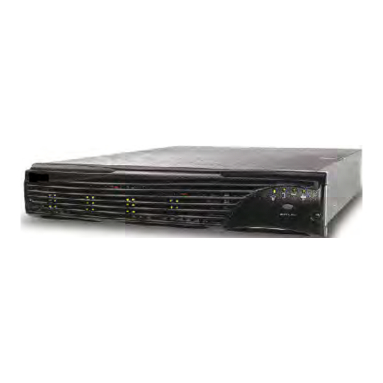
Congratulations on the purchase of your new OmniStor 4000F Series Storage System from Rackable Systems Inc. This OmniStor 4000F Series is a very high-performance fully fault-tolerant 2 Gb Fibre Channel-to-Fibre Channel JBOD storage system. It’s unique 2U design is optimized to fit in the compact space of today’s data centers rack environments and as a deskside tower system. - Page 10 About this Manual The OmniStor 4000F is a 12-Bay 3.5" (2U) rackmount JBOD storage solution. The storage enclosure includes dual Disk IO cards, four optical transceivers, dual power supplies, dual AC power cords, SES Controller card, and a removable cooling fan module. It also includes configuration software, DB-9 null modem cable, and a rackmount rail kit.þ...
-
Page 11: Typographical Conventions
Italic text indicates the item that is selected or chosen. Key strokes are enclosed in brackets, e.g., <Esc>, <K>, or <Enter>. Customer Care You will find warranty, customer service and technical support on the Rackable Systems web site. Refer to http://www.rackable.com. Typographical Conventions... - Page 12 About this Manual Features The OmniStor 4000F Series Storage Systems are designed for mission critical applications that require the highest performance with uncompromised data reliability, while maintaining exceptionally high throughput. The storage system is ideally suited for high bandwidth data intensive applications, such as electronic commerce, digital video, CAD, seismic research, digital pre-press, 3-D imaging, and SAN environments.
-
Page 13: Getting Started
Chapter 1 Getting Started This chapter provides a description of the enclosure components and its onboard monitoring systems. The Components section identifies and gives a complete description of each major component. The Monitoring section describes the enclosure’s LEDs, and the manner in which normal and abnormal conditions are presented. - Page 14 Chapter 1 - Getting Started At a Glance The following illustrations show the featured components of the OmniStor 4000F Series Storage System. Familiarize yourself with its components prior to installing and using the storage system. 350-watt hot-pluggable independent power supplies...
-
Page 15: Components
Chapter 1 - Getting Started Components This section provides a description of each of the major components that comprise the OmniStor 4000F Series Storage System. Front Bezel The front bezel houses the Status LEDs, Drive LEDs, and alarm reset button. When removed, the user has access to the disk drives. -
Page 16: Power System
Chapter 1 - Getting Started Power System Standard AC Hot Swappable Power Supplies The AC power system consists of two 350-watt hot-pluggable power supplies, each with independent AC power cords and cooling fans. This power system provides the enclosure with “N+1” redundant power. Each power supply has auto-switching circuitry for use with either 100V or 240V AC systems. -
Page 17: Optional Dc Hot Swappable Power Supplies
Chapter 1 - Getting Started Optional DC Hot Swappable Power Supplies The DC power system is designed to allow the storage system to be installed with Telco system hardware installations. It consists of two 350-watt hot-pluggable power supplies, each with independent DC power cables and cooling fans. It provides the enclosure with “N+1” redundant power with Telco hardware. -
Page 18: Cooling Fan Module
Chapter 1 - Getting Started The power feed must be electrically isolated from any AC power source, provide a reliable connection to earth (battery room positive bus is connected to the grounding electrode), and capable of providing up to 600 watts of continuous power per feed pair. Overcurrent Protection Requirements Overcurrent protection devices must be provided as part of each equipment rack. -
Page 19: Cooling Fan Module
Chapter 1 - Getting Started If any one fan should fail, cooling redundancy and efficiency are degraded. The cooling fans and enclosure temperature are constantly monitored by the SES processor for fault conditions. In the event of a fault condition the front panel Fan Status LED will change from a green state to a solid amber state in the case of a fan failure, or to a blinking amber green state in the case of an over-temperature condition. - Page 20 Chapter 1 - Getting Started The SES Controller card has a firmware-based VT-100 interface which provides an option to manage fan speed. This option provides a whisper mode fan operation for noise sensitive environments. When enabled (default), and based on a set of conditions, the software will manage the cooling fans RPM speed to maintain the enclosure temperature while minimizing noise levels.
-
Page 21: Ses Controller Card
Chapter 1 - Getting Started SES Controller Card WARNING: The SES Controller card is NOT HOT SWAPPABLE. You must POWER DOWN the enclosure prior to removing or inserting this card. The SES Controller card provides the built-in environmental and system status monitoring. It also houses the switches for setting the drive spin up options. - Page 22 Chapter 1 - Getting Started Viewed from the front of the enclosure Slot 1 Slot 4 Slot 7 Slot 10 Slot 2 Slot 5 Slot 8 Slot 11 Slot 3 Slot 6 Slot 9 Slot 12 Drive Slot Location Drive Device ID Settings Located on the SES Controller card face plate are a set of switches.
- Page 23 Chapter 1 - Getting Started NOTE: If a hard address ID conflict occurs during Fibre Channel loop initialization, the Fibre Channel protocol will dynamically set the drive IDs. This could cause problems with some software products. Switches 4, 5, and 6 are not used. Spin-Up Settings Switches 7 and 8 control the drive spin-up functions.
-
Page 24: Disk I/O Card
Chapter 1 - Getting Started Disk I/O Card The Disk I/O card provides the Fibre Channel connectivity from the host computer(s) to the disk drives, and provides drive channel expansion through daisy chaining when in Single Bus mode. This card’s design incorporates an active hub, and provides automatic loop regeneration (LRC) and port bypass. - Page 25 Chapter 1 - Getting Started Also located on the Disk I/O card is a jumper, (JP3), which allows the enclosure’s internal hubs to be configured for split-bus operations. When the enclosure is setup for a split-bus configuration, daisy chaining enclosures is not supported. When configured for split-bus operations, the drives are configured as two independent buses, the left six drives (slots 7 - 12) are seen through the P1 connectors and the right six drives (slots 1 - 6) are seen through the P2 connectors.
- Page 26 Chapter 1 - Getting Started NOTE: Refer to the Installation chapter for transceiver installation procedures. Dust covers are provided to protect the transceivers’ optics. It is highly recommend that the dust covers be installed when a connector is not in place. Install the Dust Covers when the optical transceiver port is not in use.
-
Page 27: Control And Monitoring
Chapter 1 - Getting Started Control and Monitoring An integral part of the OmniStor 4000F Series Storage System is its control and monitor capabilities. The SES processors provide monitoring data for the enclosure environmental conditions such as enclosure temperature, cooling fans, power supplies, and FC Loop status. This data is reported to the monitoring system to provide LED and audible alarm notifications. -
Page 28: Status Indicator Leds
Chapter 1 - Getting Started Status Indicator LEDs The Status Indicator LEDs comprise the Power-On LED, Channel Status LED, Power Supply Status LED, and Fan Status LED. These series of LEDs are grouped on the right side of the front bezel directly above the Alarm Reset button. The following is a description of each of these LEDs. -
Page 29: Audible Alarm
Chapter 1 - Getting Started Audible Alarm An audible alarm will sound when any of the enclosure’s component status changes to an abnormal state. To silence the alarm, press the Alarm Reset button located on the front bezel. The corresponding alarm’s LED will remain illuminated until the condition returns to a normal state. - Page 30 Chapter 1 - Getting Started Audible Alarm...
-
Page 31: Topologies And Operating Modes
Chapter 2 Topologies and Operating Modes This chapter provides an overview of the supported operating modes and topologies. This information should provide you with an understanding to make the best choices for the optimum configuration that compliments your storage system solution. Essentially there are two operating modes available with the JBOD (Just a Bunch of Drives) topology. -
Page 32: Jbod Topology
Chapter 2 - Topologies and Operating Modes JBOD Topology Split Bus Dual-Loop Mode The Split Bus Dual-Loop mode provides a basic single enclosure where the drive plane is split into two independent six drive dual-loop FC-AL JBOD configurations. A jumper, (JP3), located on the Disk I/O card will enabled the split bus mode. - Page 33 Chapter 2 - Topologies and Operating Modes Single Bus Dual-Loop Mode The Single Bus Dual-Loop mode provides a basic single enclosure where the drive plane is configured as a continuous twelve drive single bus dual-loop FC-AL JBOD configuration. You also have the ability to add additional drives through daisy-chain enclosures, to a maximum of 96 disk drives in a dual-loop FC-AL configuration.
-
Page 34: Fibre Channel Media Types
Chapter 2 - Topologies and Operating Modes Fibre Channel Media Types Optical transceivers are provided with the enclosure. However, both copper and optical media types are supported. Copper provides a lower cost solution, although it is not as reliable as Fibre optic cable. It serves distances up to 10 meters between nodes. Fibre optical is a higher cost solution, however, it provides a more reliable media and supports distances up to 300 meters between nodes. -
Page 35: Setup And Installation
Chapter 3 Setup and Installation Overview This chapter describes the procedures to install and setup the OmniStor 4000F Storage System. Each section will step you through the hardware installation, cabling and topology configurations. It is important to thoroughly review this information and perform the steps of procedures in each applicable section in the order in which they are presented. -
Page 36: Storage System Detailed Installation
Chapter 3 - Setup and Installation Storage System Detailed Installation This section describes preparing and installing the OmniStor 4000F Storage System enclosure(s) into the rack cabinet or the enclosure into its tower stand (refer to “Installing the Storage System into the Tower Stand” on page 27). After installing the hardware components, go to the “Operating Mode Configuration and Cabling”... - Page 37 Chapter 3 - Setup and Installation Locate the mounting rails and mounting hardware in the accessory kit (some installations require cage nuts and others use standard nuts). NOTE: It will be helpful to have an assistant available during the installation. Install the rear mounting rails.
- Page 38 Chapter 3 - Setup and Installation Front Rack Vertical Member Mounting Screw Mounting Chassis Ear Screw Attaching the Chassis Ears Re-install the power supplies. Slide each power supply into its empty bay and ensure it seats completely, and that the release latch resets.
-
Page 39: Installing The Storage System Into The Tower Stand
Chapter 3 - Setup and Installation Installing the Storage System into the Tower Stand Remove the storage system from its shipping carton and inspect for obvious damage. Remove and open the accessory kit. Inside you will find the power cable(s), serial communication cable, and the documentation/software CD. - Page 40 Chapter 3 - Setup and Installation Mounting Screw Mounting Screws Mounting Screws Inserting and Securing the Chassis 11 Re-install the cooling fan module. Slide it into its open bay and ensure it seats Installing the Storage System into the Tower Stand...
-
Page 41: Completing The Installation
Chapter 3 - Setup and Installation completely, and the release latch resets. 12 Re-install the power supplies. Slide each power supply into its open bay and ensure it seats completely, and the release latch resets. 13 Continue now with “Completing the Installation” on page 29. Completing the Installation Install the disk drives. - Page 42 Chapter 3 - Setup and Installation Attaching the Front Bezel (Rack and Tower Models) Secure the front bezel using a Phillips screwdriver by rotating the fasteners clockwise one-quarter turn. Install the SFP Transceivers. Insert the transceiver(s) into each of the SFP cages on the Disk I/O cards. The transceiver can only be installed one way.
- Page 43 Chapter 3 - Setup and Installation Installing Transceivers (AC Power Supplies Only) Install the power cords and secure them using the power cord bales. NOTE: For DC Power Supplies, skip to “Cabling the DC Power Supplies” on page 32. Ensure that the orientation is such that when the power cord is inserted, the bale will be on top of the cord and will fit over and onto the cord.
-
Page 44: Cabling The Dc Power Supplies
Chapter 3 - Setup and Installation Repeat steps 3(a) and 3(b) for the other power cord. Repeat the above steps for each additional storage system enclosure you will be installing with AC power supplies. This completes the physical hardware installation. Cabling the DC Power Supplies NOTE: Refer to “DC Power Supply Connector Pinout”... -
Page 45: Before You Continue
Chapter 3 - Setup and Installation Before You Continue... The the next section, Operating Mode Configuration and Cabling, includes steps and diagrams for setting the SES Controller card switches and attaching the required Fibre Channel data cables for configuration. Locate the applicable operating mode topology and follow the steps and diagrams provided. -
Page 46: Operating Mode Configuration And Cabling
Chapter 3 - Setup and Installation Operating Mode Configuration and Cabling In this first section you will find the instructions for setting the SES Controller card switches. Following that you will find illustrated instructions to setup and cabling the specific operating mode topology. SES Controller Card Switch Settings A word about Fibre Channel device IDs. - Page 47 Chapter 3 - Setup and Installation Refer to the sample illustration to see how an ID range is assigned. Switch Ranges Down Down Down IDs 0-11 IDs 16-27 Down Down IDs 32-43 Down Down Down IDs 48-59 Down Down IDs 64-75 Down IDs 80-91 Down...
- Page 48 Chapter 3 - Setup and Installation “DL” Switch 7 “RM” Switch 8 Drive Spin-up Mode Down Drive motor spins up after a delay of 12 (may vary depending on drive type) seconds times the numeric device ID setting of the associated drive. Drive motor will not spin-up.
- Page 49 Chapter 3 - Setup and Installation Omni JBOD ( Stor 4000F) Split Bus Dual-Loop Mode The Split Bus Dual-Loop mode provides a basic single enclosure where the drive plane is divided into two six drive dual-loop configurations. It’s important to note that this mode is only a single enclosure solution and cannot be expanded.
- Page 50 Locate the JP4 jumper and position the jumper for the desired speed setting. Install the jumper on one pin only for 2 Gb mode or install it on both pins for 1 Gb mode. Disk I/O Card Jumper Settings for the OmniStor 4000F Series JUMPER...
- Page 51 Chapter 3 - Setup and Installation JBOD – Split Bus Dual-Loop Cabling Diagram Set the Host HBA ID. Choose a hard ID address for the host HBA(s) that will not conflict with any of the drive ID ranges. NOTE: If soft addressing is used on the host HBA, most likely there will be a conflict.
- Page 52 Locate the JP4 jumper and position the jumper for the desired speed setting. Install the jumper on one pin only for 2 Gb mode or install it on both pins for 1 Gb mode. Disk I/O Card Jumper Settings for the OmniStor 4000F Series JUMPER...
- Page 53 Chapter 3 - Setup and Installation CAUTION: The bus speed must be set to the same setting between the disk drives and the Disk I/O card(s). For example, if you have an expansion enclosure and you are using 2 Gb drives in both enclosures, the Disk I/O cards must be set to 2 Gb mode.
- Page 54 Chapter 3 - Setup and Installation JBOD – Split Bus Dual-Loop Cabling Diagram Using Multiple Hosts Set the Host HBA ID. Choose a hard ID for the host HBA(s) that will not conflict with any of the drive ID ranges. NOTE: If soft addressing is used on the host HBA, most likely there will be a conflict.
- Page 55 Chapter 3 - Setup and Installation You can also use dual ported HBA’s in your host systems, or a hub/switch. For custom cabling configurations, remember that the upper Disk I/O card communicates on Loop A and the lower Disk IO card on Loop B. The “D1” connection provides access to the left six drive slots (7-12) and the “D2”...
- Page 56 Chapter 3 - Setup and Installation Single Bus Dual-Loop Mode This operating mode provides the capabilities for multiple JBOD enclosures using daisy-chain configurations in a dual loop topology. Single Host and HBA Verify the jumper (JP3) setting on the Disk I/O card is set for single bus operations. Loosen the two captive fastener screws for the Disk I/O card and remove it from the enclosure.
- Page 57 Chapter 3 - Setup and Installation Omni Disk I/O Card Jumper Settings for the Stor 4000F Series JUMPER INSTALLED BOTH PINS INSTALLED ONE PIN (OFFSET) Wahoo Controllers Only * Non-Wahoo Controllers Wahoo Controllers Only * Non-Wahoo Controllers Split Bus Mode * Single Bus Mode JBOD Enclosures Only JBOD Enclosures...
- Page 58 Chapter 3 - Setup and Installation Choose a hard ID address for the host HBA(s) that will not conflict with any of the drive ID ranges. NOTE: If soft addressing is used on the host HBA, most likely there will be a conflict.
- Page 59 Chapter 3 - Setup and Installation Multiple Enclosures with one or more Host(s) and HBA(s) Verify the jumper (JP3) setting on the Disk IO card is set for single bus operations. Loosen the two captive fastener screws for the Disk I/O card and remove it from the enclosure.
- Page 60 Chapter 3 - Setup and Installation Omni Disk I/O Card Jumper Settings for the Stor 4000F Series JUMPER INSTALLED BOTH PINS INSTALLED ONE PIN (OFFSET) Wahoo Controllers Only * Non-Wahoo Controllers Split Bus Mode * Single Bus Mode JBOD Enclosures Only JBOD Enclosures 1 Gb/sec Bus Speed Mode * 2 Gb/sec Bus Speed Mode...
- Page 61 Chapter 3 - Setup and Installation Omni Disk I/O Card Jumper Settings for the Stor 4000F Series JUMPER INSTALLED BOTH PINS INSTALLED ONE PIN (OFFSET) 1 Gb/sec Bus Speed Mode * 2 Gb/sec Bus Speed Mode * indicates default setting Re-install the Disk I/O card.
- Page 62 Chapter 3 - Setup and Installation 10 Connect a Fibre Channel data cable from the host HBA port to the “D1” connector on the upper Disk I/O card. This provides access to Loop A. To access Loop B: connect another Fibre Channel data cable to a second Host HBA or a second port on the first HBA, then to the “D1”...
- Page 63 Chapter 3 - Setup and Installation To access Loop B: connect another Fibre Channel data cable from “D2” on the first enclosure lower Disk I/O card to the daisy-chain enclosure lower Disk I/O card “D1” connector. NOTE: For additional daisy-chain enclosures, continue connecting the Disk I/O cards’...
-
Page 64: Upgrades
At some point you may have a need to upgrade your storage system to increase the storage capacities and/or the RAID capabilities. The OmniStor 4000F Series Storage System provides you with this ability to meet your expanding data storage requirements. -
Page 65: Powering On The Storage System
Chapter 3 - Setup and Installation Powering On the Storage System After you have the system setup and installed, you are ready to power on the storage system enclosure(s). NOTE: Ensure that the data cables, power cables, or other objects are not obstructing the air flow exiting the cooling fan module. - Page 66 Chapter 3 - Setup and Installation Powering Off the Storage System...
-
Page 67: Managing And Monitoring
Chapter 4 Managing and Monitoring In this chapter you will find information about using the enclosure’s onboard monitoring systems. It also contains the procedures to update the enclosure’s SES Controller card firmware. Using a VT-100 terminal (or emulation) connected to the SES RS-232 Service port provides an interface to the enclosure’s monitoring system and firmware. -
Page 68: Status Indicator Leds
Chapter 4 - Managing and Monitoring Status Indicator LEDs The Status Indicator LEDs located above the Alarm Reset button, comprise the Power-On LED, Channel Status LED, Power Supply Status LED, and Fan Status LED. The following are descriptions of each of the LEDs. Power-On LED The Power-On LED signifies that the enclosure is powered on and will be illuminated green when power has been applied. -
Page 69: Drive Status Leds
Chapter 4 - Managing and Monitoring The Drive Status LEDs are also used for the “One-Touch Annunciation” Configuration Display system. Pressing and holding the Alarm Reset button indicates the SES Controller card switches 1-3 settings, Disk I/O card speed setting, and the presence of IO cards and controller cards. -
Page 70: Audible Alarm
Chapter 4 - Managing and Monitoring Drive Carrier LitePipes On each disk drive carrier are “LitePipes.” They are located on the lower right side of each drive carrier. The LitePipes present some of the information provided by the front bezel Drive LEDs, that is, drive activity information and drive fault (failure) notifications when the front bezel is removed. -
Page 71: One-Touch Annunciation Configuration Display
Chapter 4 - Managing and Monitoring One-Touch Annunciation Configuration Display The “One-Touch Annunciation” Configuration Display system is an easily accessible press-to-touch display of the SES Controller card swtiches 1 through 3 settings, fan control setting, Host IO card and Disk I/O card speed mode, presence of Disk I/O cards, presence of Host I/O cards, and presence of RAID Controllers. -
Page 72: Vt-100 Interface Enclosure Monitoring
Chapter 4 - Managing and Monitoring VT-100 Interface Enclosure Monitoring Another feature of the OmniStor 4000F Series Storage System is the ability to modify the system through a VT-100 terminal interface. The user can interact with the system through a VT-100 terminal interface. The firmware based monitoring program allows users to view component status and firmware specific information. - Page 73 Chapter 4 - Managing and Monitoring At the screen cursor, type <Control-E>. The Enclosure Terminal Utility menu will appear. Enclosure Terminal Utility Screen To monitor the enclosure components, select option “1” Show Enclosure Environment Status by pressing the <1> key. The screen provides a status list of the internal components such as disk drives in a specific slot, temperature of the thermal sensors, cooling fan status, power supply status, and statistics on enclosure “up time.”...
-
Page 74: Ses Commands Debug
Chapter 4 - Managing and Monitoring SES Commands Debug This feature (Option 2) provides manufacturers and developers the ability to monitor “read and write” command buffers for both SES processors. This option allows the user to scroll back through the buffer data, or select the “Transfer>Capture Text” to save the buffer captures to a text file. -
Page 75: Uploading Ses Controller Card Firmware
Chapter 4 - Managing and Monitoring Uploading SES Controller Card Firmware The following information describes the procedures to upload new firmware to the SES Controller card. The preferred method is to take the enclosure off-line first, then perform the upgrade. This prevents bus reset errors. Connect one end of the null-modem RS-232 cable to the RS-232 Service port located on the SES Controller card. - Page 76 Chapter 4 - Managing and Monitoring The Enclosure Terminal Utility menu will appear. Enclosure Terminal Utility Screen Select option “5” Firmware Upload by pressing the <5> key. Upload Firmware Screen Press the <u> key (lower case) to start the upload. Using the mouse, click on the pull-down menu Transfers and select “Send.”...
- Page 77 Chapter 4 - Managing and Monitoring NOTE: Ensure that the protocol “Xmodem” is selected. From the Xmodem send screen you can monitor the progress of the upload. You can safely stop the transfer without affecting your existing firmware any time during the transfer until it has been completed.
-
Page 78: Enclosure Fan Speed Control
Chapter 4 - Managing and Monitoring Enclosure Fan Speed Control The SES Controller card has a firmware-based VT-100 interface which provides an option for fan speed control. This allows the user with the choice to enable or disable the automatic control feature. - Page 79 Chapter 4 - Managing and Monitoring When this option is enabled, the software will control the RPM of the cooling fans based on enclosure temperature parameters and its installed component. For example, if any one or a combination of the following occurs, the cooling fan RPMs will be set to the maximum software controlled RPM: a disk drive is removed from any of the drive slots 4 through 9, a power supply is removed, one of the cooling fans in the cooling fan module fails, a temperature sensor fails, or a SES processor fails.
- Page 80 Chapter 4 - Managing and Monitoring The jumpers JP1 and JP2 are by default are offset which enables the use of the automatic fan speed control. The jumper JP1 controls Fan 0 and JP2 controls Fan 1. Placing the included jumper on both pins of each jumper will override the automatic setting and set the fans to maximum power.
-
Page 81: Troubleshooting
Chapter 5 Troubleshooting This chapter provides typical solutions for problems you may encounter while using the OmniStor 4000F Series Storage System. General Enclosure Problems Symptom Reason Solution Fails to power on. Power cord(s) not connected Verify that the power cord is properly properly. -
Page 82: Common Fibre Loop/Bus Problems
Chapter 5 - Troubleshooting Common Fibre Loop/Bus Problems Fibre loop or bus problems can usually be attributed to cabling issues, transceivers, speed mode setting or possibly a faulty Disk I/O card. Refer to the chart below to review troubleshooting and fault isolation procedures to assist you in identifying the suspect component or problem, and the possible solutions. -
Page 83: Common Problems And Interpreting The Leds
Chapter 5 - Troubleshooting Symptom Reason Solution Host HBA failed to boot. Ensure that the Host Fibre Channel HBA booted and the driver was properly loaded during the host system boot process. Refer to your Fibre Channel HBA user’s guide for more information. -
Page 84: Terminal And Com Port Problems
Chapter 5 - Troubleshooting Terminal and COM Port Problems Symptom Reason Solution Screen continuously puts The likely cause of this problem 1 Shut down the controller. out garbage characters. is a baud rate mismatch between Refer to the software user’s guide. the terminal emulator and the enclosure. -
Page 85: Maintenance
Chapter 6 Maintenance In this chapter you will find the maintenance procedures to replace individual components, as well as the entire storage system enclosure. Removing the Front Bezel Using a Phillips screwdriver, unlock the two front bezel fasteners. Unlocking the Front Bezel Rotate the fasteners counterclockwise one-quarter turn to unlock. - Page 86 Chapter 6 - Maintenance Grasp and pull the front bezel from the enclosure. Refer to the illustration below. Removing the Front Bezel Removing the Front Bezel...
-
Page 87: Replacing The Cooling Fans
Chapter 6 - Maintenance Replacing the Cooling Fans NOTE: The cooling fan module is hot-swappable. WARNING: Do not operate the enclosure for extended periods of time, greater than five (5) minutes, with the cooling fan module removed. No cooling is available while the fan module is removed. - Page 88 Chapter 6 - Maintenance Remove the replacement cooling fan module from the shipping container and inspect for obvious damage. Save the packaging material. Align the cooling fan module with the opening fan bay and push the module into the enclosure until it completely seats. The latch will reset when the module is completely seated.
-
Page 89: Replacing An Ac Power Supply
Chapter 6 - Maintenance Replacing an AC Power Supply NOTE: The AC power supply is hot-swappable. The storage system will continue to function normally with one power supply during replacement. Turn the On/Off switch to the “Off ” position on the affected power supply. Disconnect the AC power cord. - Page 90 Chapter 6 - Maintenance Using your thumb and fore finger, squeeze the power supply release latch while pulling the power supply from the enclosure. Remove the replacement power supply from the shipping container and inspect for obvious damage. Save the packaging material. Install the new power supply by sliding it into its open bay and ensuring it seats completely and the release latch resets.
-
Page 91: Replacing A Dc Power Supply
Chapter 6 - Maintenance Replacing a DC Power Supply NOTE: The DC power supply is hot-swappable. The storage system will continue to function normally with one power supply during replacement. Turn the On/Off switch to the “Off ” position on the affected power supply. Disconnect the DC power cable. - Page 92 Chapter 6 - Maintenance Using your thumb and fore finger, slide the power supply release latch to the right while pulling the power supply from the enclosure. Remove the replacement power supply from the shipping container and inspect for obvious damage. Save the packaging material. Install the new power supply by sliding it into its open bay and ensuring it seats completely and the release latch resets.
-
Page 93: Replacing A Disk Drive
Chapter 6 - Maintenance Replacing a Disk Drive WARNING: Drives and printed circuit board components are sensitive to electrostatic discharge. To prevent operating failure or damage, observe the following: Establish a ground for yourself by using the wrist grounding strap, or by touching the metal chassis prior to handling or installing the drives or printed circuit board components. - Page 94 Chapter 6 - Maintenance The drive carrier has tension clips which ensures that the drive fits very tight. It requires some force to remove or install the drive. Remove the replacement disk drive from its shipping container and remove the anti-static protection packaging.
-
Page 95: Replacing The Disk I/O Card
Chapter 6 - Maintenance Replacing the Disk I/O Card NOTE: The Disk I/O Card is hot-swappable. Locate and verify which is the faulty Disk I/O card. Remove the Fibre Channel data cables from the transceiver(s) that are to be removed. Insert the dust covers on the data cable connector(s). - Page 96 Chapter 6 - Maintenance protect the optics. Using a flat-blade screwdriver, loosen the two captive fastener screws that secure the card. Removing the Disk I/O Card Using the captive fastener screws, gently pull the card from the enclosure. Note the position of the jumpers on the faulty card. Remove the new replacement card from the shipping container and inspect for obvious damage.
- Page 97 Chapter 6 - Maintenance The transceiver can only be installed one way. Note the orientation and ensure you are inserting it correctly. Push the transceiver fully into the SFP cage so that it completely seats. The transceiver protrudes approximately 1/2-inch from the Disk I/O card face plate when it’s completely seated.
-
Page 98: Replacing The Ses Controller Card
Chapter 6 - Maintenance Replacing the SES Controller Card WARNING: The SES Controller Card is NOT HOT-SWAPPABLE. You must POWER DOWN the storage enclosure to remove or install this card. Power down the storage enclosure, refer to “Powering Off the Storage System” on page 53. -
Page 99: Replacing The Enclosure
Chapter 6 - Maintenance Replacing the Enclosure WARNING: Printed circuit board components are sensitive to electrostatic discharge. To prevent operating failure or damage, observe the following: Establish a ground for yourself by using a wrist grounding strap, or by touching the metal chassis prior to handling or installing a printed circuit board component. - Page 100 Chapter 6 - Maintenance Install the replacement storage enclosure. For Rack Installations. Follow the installation procedures in Chapter 3, “Installing the Storage System Enclosure into the Rack Cabinet” on page 24. For Deskside Tower Installations. Follow the installation procedures in Chapter 3, “Installing the Storage System into the Tower Stand”...
-
Page 101: Technical Information
Appendix A Technical Information Specifications Omni Technical Specifications for the Stor 4000F Storage System Operating Environment Operating +40°F to +95°F (+5°C to +35°C) Non-Operating -4°F to +158°F (-20°C to +70°C) Relative Humidity Operating/Non-Operating 5% - 98% (non-condensing) Power Requirements 85 - 264 VAC (Input AC voltage) 4.5 - 1.0 Amperes (Input Current) 47-63 Hz (Input Frequency) Dimensions Rack Mount Unit (HxWxD) - Page 102 Appendix A - Technical Information Omni Technical Specifications for the Stor 4000F Storage System Safety Requirements CAN/CSA C22.2 #60950-00 (in compliance with) UL 60950 3rd Edition CB IEC 60950 Edition 3 CE Compliance (EMC) 89/336/EEC EMC Directive EN55024 Shock Operating 1.0 G, 2 - 50 ms Non-Operating 20.0 G, 2 - 20ms...
-
Page 103: Port Information
Appendix B Port Information This appendix contains pin signal information for the SES Controller Service Port, and the SPF Transceivers installed in the Disk I/O cards. SES Controller Card Service Port Service port is provided to access the SES Controller using a standard null-modem cable. Through this RS-232 service port you can use a VT-100 terminal or emulation such as HyperTerminal, to access the onboard firmware for monitoring and maintenance, and firmware update operations. -
Page 104: Null-Modem Cable
Appendix B - Port Information Null-Modem Cable This cable is a DB-9 (female) to DB-9 (female) null-modem type, and is used to connect a VT-100 terminal (or emulation terminal) to the SES Controller Card Service port. DB-9 to DB-9 Null-Modem Cable Pin Signals Null-Modem Cable... -
Page 105: Optical Sfp Transceiver
Appendix B - Port Information Optical SFP Transceiver The Disk I/O cards use a hot-swappable Small Form-Factor Pluggable (SFP) transceiver. The SFP optical transceiver provides operations up to 2.5 Gb/sec. The transceiver includes a lost signal detect circuit which provides TTL logic high output when an unusable input signal is detected. -
Page 106: Dc Power Supply Connector Pinout
Appendix B - Port Information DC Power Supply Connector Pinout CAUTION: If the enclosure is connected to a DC power feed source that is not within the designated -48VDC range, damage might occur to the unit. A DC power cable is included with the 48VDC Power Supplies and is used to connect to a DC power feed system. -
Page 107: Regulatory Information
Appendix C Regulatory Information Compliance Information Statement Rackable Systems, Inc. 1933 Milmont Ave. Milpitas, California 95035 (408) 240-8000 declare under our sole responsibility that the product, Type of Equipment: Storage System Enclosure Model Number: OmniStor 4000S to which this declaration relates is in conformity with the Title 47 of the US Code of Federal Regulations, Part 15 covering Class A personal computers and peripherals. -
Page 108: Fcc Class A Radio Frequency Interference Statement
Rackable Systems is not responsible for any interference caused by unauthorized modifications to this equipment. It is the user’s responsibility to correct such interference. -
Page 109: Class A Taiwanese Statement
Marking by the “CE” symbol indicates compliance of the device to directives of the European Community. A “Declaration of Conformity” in accordance with the above standards has been made and is available from Rackable Systems upon request. Class A Taiwanese Statement... -
Page 110: Power Cord Selection
Appendix C - Regulatory Information Power Cord Selection This enclosure is intended for indoor use only. This enclosure is intended to be plugged into a 6A branch circuit in Europe. To select the proper power cord: For 110 Volt Operation – Use a UL Listed/CSA Labeled cord set consisting of a minimum 18 AWG, type SVT or SJT three conductor cord, terminating in a molded connector body having an IEC CEE-22 female configuration on one end and a molded-on parallel blade grounding type attachment plug rated 15A, 125V... -
Page 111: Index
Index Device ID Device ID Ranges 17, 58 Alarm Speaker Dimensions Attaching the Chassis Ears Disk I/O Card Rack mount Replacing Tower Disk I/O Link LED is not illuminated Attaching the Front Bezel Drive Activity LEDs Attaching the Power Cord Bales Drive ID Settings Attaching the Rails 16, 56... - Page 112 16, 56 Interpreting the LEDs Power-On LED Japanese Statement Rack Cabinet Installation Class A RAID Controller Enclosure JBOD General Problems Single Bus Dual-Loop Relative Humidity Split Bus Dual-Loop Removing the Front Bezel Replacing Enclosure Replacing a DC Power Supply Replacing a Disk Drive Replacing an AC Power Supply Channel Status 16, 56...
Need help?
Do you have a question about the OMNISTOR 4000f SERIES and is the answer not in the manual?
Questions and answers