Table of Contents
Advertisement
Installation and Operation Instructions
FOR YOUR SAFETY: This product must be installed and serviced by a professional service technician,
qualified in hot water boiler and heater installation and maintenance. Improper installation and/or operation
could create carbon monoxide gas in flue gases which could cause serious injury, property damage, or
death. Improper installation and/or operation will void the warranty.
WARNING
If the information in this manual is not
followed exactly, a fire or explosion may
result causing property damage, personal
injury or loss of life.
Do not store or use gasoline or other
flammable vapors and liquids in the vicinity of
this or any other appliance.
WHAT TO DO IF YOU SMELL GAS
• Do not try to light any appliance.
• Do not touch any electrical switch; do not
use any phone in your building.
• Immediately call your gas supplier from a
nearby phone. Follow the gas supplier's
instructions.
• If you cannot reach your gas supplier, call
the fire department.
Installation and service must be performed
by a qualified installer, service agency, or gas
supplier.
Installation and Operation
Instructions for
M
ASCOT
Floor-Standing, Modulating
Gas, Condensing, Combination Boiler
Model MFTCF
140,000 BTU/hr
199,000 BTU/hr
Natural Gas (NG) - Factory Configuration
•
•
Propane Gas (LP) - Field-Convertible
Assurez-vous de bien suivres les instructions
données dans cette notice pour réduire au
minimum le risque d'incendie ou d'explosion
ou pour éviter tout dommage matériel, toute
blessure ou la mort.
Ne pas entreposer ni utiliser d'essence ou ni
d'autres vapeurs ou liquides inflammables dans
le à proximité de cet appareil ou de tout autre
appareil.
QUE FAIRE SI VOUS SENTEZ UNE ODEUR DE
• Ne pas tenter d'allumer d'appareils.
• Ne touchez à aucun interrupteur. Ne pas vous servir
des téléphones dans le bâtiment où vous vous
trovez.
• Appelez immédiatement votre fournisseur de
gaz depuis un voisin. Suivez les instructions
du fournisseur.
• Si vous ne pouvez rejoindre le fournisseur de
gaz, appelez le sservice des incendies.
L'installation et l'entretien doivent être assurés par
un installateur ou un service d'entretien qualifié
ou par le fournisseur de gaz.
FT
®
AVERTISSEMENT
GAZ:
Document 1320B
Advertisement
Table of Contents

Related Manuals for Laars MFTCF140


Summary of Contents for Laars MFTCF140
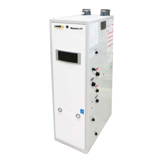
- Page 1 Installation and Operation Instructions Document 1320B Installation and Operation Instructions for ASCOT ® Floor-Standing, Modulating Gas, Condensing, Combination Boiler Model MFTCF 140,000 BTU/hr 199,000 BTU/hr Natural Gas (NG) - Factory Configuration • • Propane Gas (LP) - Field-Convertible FOR YOUR SAFETY: This product must be installed and serviced by a professional service technician, qualified in hot water boiler and heater installation and maintenance.
-
Page 2: Table Of Contents
LAARS Heating Systems TABLE OF CONTENTS SECTION 1 Product Accessories 1.1 Introduction ............1 4.16 Disposal of Condensate ........43 4.17 Electrical Wiring Connections ......44 1.2 Included with the Appliance ........ 1-2 4.18 DIP Switches ............ 45 4.19 Control Board, Electrical Diagram ..... 47 SECTION 2 4.20 Ladder Diagram .......... -
Page 3: Product Accessories
Kit # R20771 H2373900A Top Access Panel Top Access Panel The Laars Mascot FT condensing gas boiler is confi gured for Front Panel Knob The Laars Mascot FT condensing gas boiler is confi gured for Front Panel Knob Natural Gas (NG) from the factory. If your gas supply is Propane Natural Gas (NG) from the factory. - Page 4 LAARS Heating Systems Page 2 1.2 Included with the Appliance (continued) Items Descriptions Mesh screen (3" mesh) Outdoor Sensor with Screws and Anchors Pressure Relief Valve (CH LINE 3/4″ 30psi) Model : CASH ACME F-82...
-
Page 5: Product Characteristics
Mascot FT Floor Standing Combination Boiler Page 3 SECTION 2. Product Characteristics Model Nomenclature The Model Nomenclature is shown on your Rating Plate and consists of a series of letters and numbers ( Nomenclature ) that further identifies the characteristics of your Mascot FT. FUEL SERIES SIZE... -
Page 6: Specifications
Table D pg 3 o 1869 Sismet Road, Mississauga, Ontario, Canada L4W 1W8 • 905.238.0100 • Fax 905.366.0130 www.Laars.com Litho in U.S.A. © Laars Heating Systems 1607 Document 4290A Ignition System Direct Electronic Ignition / Automatic Flame Sensing www.Laars.com Burner System... - Page 7 Detector, Exhaust Temperature High Limit Switch, Water Temperature High Limit Switch Note; The greatest installation difference between the MFTCF140 and MFTCF199, other than general output capability (BTU’s), is that the air inlet and exhaust vents are opposite. See Section 2.4...
-
Page 8: Dimensions
LAARS Heating Systems Page 6 2.3 Dimensions 3.0" 7.6 cm MFTCF140 3.3" 8 cm 15.7" 40 cm 9.2" 23 cm 3” O EXHAUST VENT 68 cm 26.7" 3” O AIR INLET 20.5" GAS CONNECTION 9.3" 39.3" HYDRONIC SUPPLY 2.7" 52.4" 133 cm HYDRONIC RETURN 4.3"... - Page 9 4.0" 10.4 cm Note; The greatest installation difference between the 6.6" 16.9 cm 15.7" 40 cm MFTCF140 and MFTCF199, other than general output capability (BTU’s), is that the air inlet and exhaust vent are opposite. See Section 2.4 3” O AIR INLET 68 cm 26.7"...
-
Page 10: Names Of Components
LAARS Heating Systems Page 8 2.4 Names of Components MFTCF140 Name of Component Name of Component Condensate Drain Hose Exhaust Vent DHW Inlet Adapter Air Pressure Sensor Condensate Trap Blower DHW Outlet Adapter PCB Bracket Condensate Heat Exchanger Hose Flame Detection Sensor... - Page 11 Mascot FT Floor Standing Combination Boiler Page 9 MFTCF199 Note; The greatest installation difference between the MFTCF140 and MFTCF199, other than general output capability (BTU’s), is that the air inlet and exhaust vent are opposite. Name of Component Name of Component...
-
Page 12: Product Flow And Characteristics
LAARS Heating Systems Page 10 2.5 Product Flow Paths and Characteristics 2.5.1 Central Heating flow. Combination Boiler Heating Mode. Water in the heating pipe is used for space heating. acteristics Operating Mode Space Heating ng mode. (Central Heating = CH mode) Water Supply d for space heating. -
Page 13: Domestic Hot Water Flow
Mascot FT Floor Standing Combination Boiler Page 11 2.5 Product Flow Paths and Characteristics uct Characteristics Operating Mode 2.5.2 Domestic Hot Water flow. Combination Boiler Domestic Hot Water Mode. Cold water passes through the exchanger and is heated via a mini indirect tank. The domestic hot water (DHW) is provided on demand. -
Page 14: Safety Regulations
Boiler. fire or explosion could result causing property damage, personal injury or loss of life. Laars cannot anticipate every circumstance A. This appliance does not have a pilot. It that might involve a potential hazard. Therefore, is equipped with an ignition device which all possible incidents are not included in our automatically lights the burner. - Page 15 - Make sure that there is no foreign object in the vent understand the Operating Information in this manual passage or rodent screen. before operating the Laars Boiler. - If you do not find any problem, do the following. Be aware of the location of the gas shut-off valve - Turn off the error state by pressing the power button and operation method.
-
Page 16: Safety Precautions And Proper Use
LAARS Heating Systems Page 14 SECTION 3 Safety Regulations 3.2 Safety Precautions and Proper Use When in Operation CAUTION Before Operation 1. Caution for Gas leak 1. Check the Gas Type (NG/LP) Frequently check for a gas leak at the gas connection When using or moving the unit for the first time, check portion with soapy water. - Page 17 Mascot FT Floor Standing Combination Boiler Page 15 WARNING Do not use the appliance for any other purpose than for heating and hot water. Do not store combustibles or flammable material such as gasoline near the appliance. Do not store other items on or near this boiler. Do not store combustible (flammable) materials such as papers.
-
Page 18: Location And Clearances
LAARS Heating Systems Page 16 SECTION 4. Installation 4.1 Location and Clearances The appliance should be located to provide clearances on all sides for maintenance and inspection. It should protected from water (dripping, spraying, rain, etc.) not be located in an area where leakage of any... -
Page 19: Wall Mount Bracket
Mascot FT Floor Standing Combination Boiler Page 17 WARNING Installations must comply with • All the local, state, provincial, and national codes, laws, regulations and ordinances. • National Fuel Gas Code, ANSI Z223.1 – The latest version. • National Electrical Code. •... -
Page 20: Combustion Air
When taken from the wall, it must they connect. be taken from out-of-doors by means of the LAARS Two permanent openings, one commencing Method 1: horizontal wall terminal. When taken from the roof, a within 12”... - Page 21 Mascot FT Floor Standing Combination Boiler Page 19 NOTICE AVIS The instructions for the installation of the venting Les instructions d'installation du système system shall specify that the horizontal portions of d'évacuation doivent préciser que les sections the venting system shall be supported to prevent horizontales doivent être supportées pour prévenir sagging;...
-
Page 22: Venting (Exhaust)
LAARS Heating Systems Page 20 SECTION 4. Installation 4.4 Venting (Exhaust) AVIS NOTICE NE PAS ÉVENT COMMUNE MASCOTTE FT UNITÉS. Mascotte FT unités ne sont jamais autorisés à DO NOT COMMON VENT MASCOT FT UNITS. partager un évent Catégorie I avec les appareils. -
Page 23: General Location Guidelines
Mascot FT Floor Standing Combination Boiler Page 21 WARNING with alternate manufacturers certified Failure to vent this Boiler in accordance with components and/or unlisted components. these instructions could cause a fire, resulting 5 . The venting must be installed according in severe property damage, personal injury or to the vent manufacturers installation death. -
Page 24: Locations For Vent Pipe Terminator
LAARS Heating Systems Page 22 SECTION 4. Installation 4.6 Locations for Vent Pipe Terminator * For clearances not specified in ANSI Z224.1 / NFPA 54 or CAN/CSA-B 149.1, please use clearances in accordance with local installation codes and the requirement of the gas supplier. -
Page 25: Direct Venting Clearances
Mascot FT Floor Standing Combination Boiler Page 23 4.6.2 Non-Direct Venting (Single Pipe) Clearances Description US Non-Direct Canadian Non-Direct Clearance above grade, veranda, porch, deck, or balcony 12 in (30 cm) 12 in (30 cm) 48 in (120 cm) below or to side of opening;... -
Page 26: Commonwealth Of Massachusetts
LAARS Heating Systems Page 24 SECTION 4. Installation 4.6.3 Venting Requirements in the Commonwealth of Massachusetts b. In the event that the requirements of the In Massachusetts the following items are required if subdivision cannot be met at the time of completion... -
Page 27: Venting Requirements In Massachusetts
Mascot FT Floor Standing Combination Boiler Page 25 NOTICE AVIS NE PAS ÉVENT COMMUNE MASCOTTE FT UNITÉS. DO NOT COMMON VENT MASCOT FT UNITS. Mascotte FT unités ne sont jamais autorisés à Mascot FT units are never permitted to share a partager un évent Catégorie I avec les appareils. -
Page 28: Air Supply And Vent Connections At The Appliance
Vent Pipe & Inlet Pipe - Clean and dry your selected PVC, CPVC vent pipe and Laars Boiler collar (socket). - You can select to the size of vent pipe(2˝ & 3˝), according to the installation conditions. - Push the pipe into the collar (socket) until it touches the bottom of the socket fitting. -
Page 29: Indoor Combustion Air
MFTCF 2. Provide two openings to allow for circulation of combustion air as specified by ANSI Z224.1/NFPA 54. In Canada refer to CAN/CSA B-149.1 Model MFTCF140 MFTCF140 Maximum Input (BTU/H) 140,000 199,000 Indoor make up air is provided, a 140 in 13 1/4"... - Page 30 LAARS Heating Systems Page 28 SECTION 4. Installation 4.8 Vent Pipe Termination (cont) Horizontal Vent Termination (cont) • Direct Vent - Optional Sidewall Snorkel Terminations Vertical Vent Termination • Direct Vent - Vertical Terminations with Sloped Roof Concentric Vent Termination •...
-
Page 31: Gas Supply And Piping
Mascot FT Floor Standing Combination Boiler Page 29 Gas Supply and Piping WARNING: Gas piping should be supported by suitable hangers or Open flame can cause gas to ignite and result in floor stands, not the appliance. property damage, severe injury, or loss of life. Review the following instructions before proceeding with the installation. - Page 32 To facilitate any future maintenance, it is also The gas connection fitting on the unit is recommended that an approved gas union fitting 1/2”(MFTCF140) or 3/4”(MFTCF199) female NPT. be installed in the supply line between the shut-off valve and the 3/4” female NPT connection on the The supply line must be sized for the maximum Combination boiler.
- Page 33 4.9 Gas Supply and Piping Combination boiler must be installed downstream of the gas meter for adequate gas supply. Combination boiler gas connection pipe not less than a 1/2” (MFTCF140) or 3/4” (MFTCF199). Suggested Natural Gas (NG) Layout Capacity : Not less than 'total capacity of connected appliances'...
-
Page 34: Gas Supply Pressure
LAARS Heating Systems Page 32 SECTION 4. Installation 4.10 Gas Supply Pressure The minimum and maximum inlet gas line pressures must be LP Gas Natural Gas Maximum Pressure 13.0" WC Maximum Pressure 10.5" WC Minimum Pressure 8.0" WC Minimum Pressure 3.5"... -
Page 35: High Altitude Installations And Orifices
See Section 4.13 for instructions to change out the to get the contact info for your nearest Laars Sales Gas Line Nozzle/Orifice in the Mascot FT. Representative. The Mascot FT does have some settings within the Control Display that can be adjusted to suit your installation altitude. -
Page 36: Natural Gas To Propane Conversion
H2373900A Top Access Panel Front Panel Knob The Laars Mascot FT condensing gas boiler is confi gured for Natural Gas (NG) from the factory. If your gas supply is Propane Front Panel Gas (LP), your boiler can be converted to burn propane gas. Also, if your boiler is already converted to burn propane, it can be modifi ed back to burning Natural Gas, using these instructions. - Page 37 20 Industrial Way, Rochester, NH 03867 • 603.335.6300 • Fax 603.335.3355 (Applications Engineering) pg 2 of 4 1869 Sismet Road, Mississauga, Ontario, Canada L4W 1W8 • 905.238.0100 • Fax 905.366.0130 www.Laars.com Litho in U.S.A. © Laars Heating Systems 1607 Document 4290A www.Laars.com...
- Page 38 20 Industrial Way, Rochester, NH 03867 • 603.335.6300 • Fax 603.335.3355 (Applications Engineering) Table D pg 3 of 4 1869 Sismet Road, Mississauga, Ontario, Canada L4W 1W8 • 905.238.0100 • Fax 905.366.0130 www.Laars.com Litho in U.S.A. © Laars Heating Systems 1607 Document 4290A www.Laars.com...
- Page 39 20 Industrial Way, Rochester, NH 03867 • 603.335.6300 • Fax 603.335.3355 (Applications Engineering) pg 4 of 4 1869 Sismet Road, Mississauga, Ontario, Canada L4W 1W8 • 905.238.0100 • Fax 905.366.0130 www.Laars.com Litho in U.S.A. © Laars Heating Systems 1607 Document 4290A www.Laars.com...
-
Page 40: Plumbing Guideline
LAARS Heating Systems Page 38 SECTION 4. Installation 4.14 Plumbing Guidelines External Plumbing and Water Connection CAUTION Guidelines Use at least the MINIMUM pipe size for the entire - Ensure pipe material meets local codes and boiler loop piping (connecting boiler to and from industry standards. - Page 41 Mascot FT Floor Standing Combination Boiler Page 39 SECTION 4. Installation 4.14 Plumbing Guidelines Diaphragm Type Expansion Tank - The air in a diaphragm-type expansion tank is separated from the water by a flexible rubber membrane. When the tank is installed in and connected to the piping of the system, water enters the other side of the tank chamber and presses down on the diaphragm.
- Page 42 LAARS Heating Systems Page 40 SECTION 4. Installation 4.14 Plumbing Guidelines Zoning with Circulation Pump - Each heating zone of a pump based system has its own circulator pump which runs when the zone needs it. - Each zone thermostat goes to a controller which controls the pumps.
- Page 43 Mascot FT Floor Standing Combination Boiler Page 41 SECTION 4. Installation 4.14 Plumbing Guidelines Zoning with Zone Valve - In a valve based system, there is one circulator pump at the boiler and each heating zone has a zone valve which opens when the zone. - Each thermostat is wired directly to the corresponding zone valve.
-
Page 44: Pressure Relief Valves
LAARS Heating Systems Page 42 SECTION 4. Installation 4.15 Pressure Relief Valves External pressure relief valves must be installed. Observe the following. Failure to comply with the guidelines on installing the pressure relief valve and discharge piping can result in personal injury, death or substantial property damage. -
Page 45: Disposal Of Condensate
Damage caused by failure to install a neutralizer kit or to adequately treat condensate will not be the manufacturer’s responsibility. Contact Laars to order Neutralizer Kit# A2123601 _________________________________________... -
Page 46: Electrical Wiring Connections
LAARS Heating Systems Page 44 SECTION 4. Installation 4.17 Electrical Wiring Connections WARNING Install wiring and electrically ground boiler in accordance with authority having jurisdiction or, in the absence of such requirements, follow the National Electrical Code, NFPA 70, and/or CSA C22.1 Electrical Code-Part 1 in Canada. -
Page 47: Dip Switches
20 Industrial Way, Rochester, NH 03867 • 603.335.6300 • Fax 603.335.3355 (Applications Engineering) Table D pg 3 of 4 1869 Sismet Road, Mississauga, Ontario, Canada L4W 1W8 • 905.238.0100 • Fax 905.366.0130 www.Laars.com Litho in U.S.A. © Laars Heating Systems 1607 Document 4290A... - Page 48 LAARS Heating Systems Page 46 SECTION 4. Installation 4.19 Control Board, Electrical Diagram...
-
Page 49: Control Board, Electrical Diagram
Mascot FT Floor Standing Combination Boiler Page 47 SECTION 4. Installation NEUTRAL 4.20 Ladder Diagram Pump1 Relay 1 Pump2 Relay 2 Pump3 Relay 6 Gas Valve Relay 4 Relay Relay Ignitor FILTER Power Detector Primary SMPS Secondary DC 30V Speed Control DC 14 V DC 5V Water... -
Page 50: Electrical Connections
LAARS Heating Systems Page 48 SECTION 4. Installation 4.21 Electrical Connections Connector Description SELV #, Location, Type Label GROUND Power Supply Line HT (120VAC) Mixing Pump HT (120V~) Igniter HT (120V~) HEAT/CP2 Central Heating Pump HT (120V~) 65001WS-12 Gas Valve... -
Page 51: Electrical Connections
Mascot FT Floor Standing Combination Boiler Page 49 SECTION 4. Installation 4.21 Electrical Connections Connector Description SELV #, Location, Type Label Flame Detect Sensor SELV (5VDC) OP.S Operation water temperature sensor SELV (5VDC) DH.S DHW temperature sensor SELV (5VDC) CH Return sensor SELV (5VDC) LWD1140-14 BG.S... -
Page 52: Control Display And Operation
LAARS Heating Systems Page 50 SECTION 5. Control Display and Operation 5.1 Control Dial and Buttons The Control Display Status Light (constant green when operating normally) The Control Display has a Control Dial (E), 4 buttons (A, B, C, D), and a Liquid Crystal Display (with 72 back-lit segments). -
Page 53: Lcd Overview
Mascot FT Floor Standing Combination Boiler Page 51 SECTION 5. Control Display and Operation 5.2 LCD Overview Anti-Freeze Lock Communicating Storage Central Mode Heating Heat Status and Installer Modes Summer Mode (warm weather Flame shutdown) Signal Outside Temp Mode or 0-10V Pump Domestic Hot Water Mode Numeric Display... -
Page 54: Operating Mode
LAARS Heating Systems Page 52 SECTION 5. Control Display and Operation 5.3 Operating Mode Operating Mode After the Power is turned on, and/or the Control Display is turned on , the Control Display will go through a ‘Start Up’ checklist and briefly show a sequence of diagnostic codes before entering into the ‘Operating Mode. -
Page 55: Status Display Mode
Mascot FT Floor Standing Combination Boiler Page 53 SECTION 5. Control Display and Operation 5.4 Status Display Mode Digital Display Status Display Parameter Description O:ot Outdoor temperature Current Outdoor temperature A: Li or A: GA Flow unit Current flow value(Li: L/m, GA: GPM) b: It CH Return Water Temperature Current Return Water Sensor Temperature C: Fr... -
Page 56: Dhw Set Point Change Mode
LAARS Heating Systems Page 54 SECTION 5. Control Display and Operation 5.5 DHW Set Point Change Mode DHW Set Point Change Modes The display shows the following information when changing water heating temperature set points. Changing between Celsius and Fahrenheit... -
Page 57: Ch Set Point Change Mode
Mascot FT Floor Standing Combination Boiler Page 55 SECTION 5. Control Display and Operation 5.6 CH Set Point Change Mode Changing between Celsius and Fahrenheit When the button D is pressed (for more than 5 seconds), temperature unit will toggle between °C and °F. -
Page 58: Installer Mode
LAARS Heating Systems Page 56 SECTION 5. Control Display and Operation 5.8 Installer Mode These changes are to be made only by a qualified technician. To c hange any of the Installer Parameters, Start by turning OFF the Power to the Display Control. - Page 59 Mascot FT Floor Standing Combination Boiler Page 57 SECTION 5. Control Display and Operation 5.8 Installer Mode Index Parameter Description 1: EH History entry History fault code (E0~E9) 2: cE Clear Error History Clearing of error History buffer 3: In System initialize System initialize to default 4: Fu...
-
Page 60: Outside Temperature (Option)
LAARS Heating Systems Page 58 SECTION 5. Control Display and Operation 5.9 Outdoor Reset Adjustment Outdoor Reset varies the control setpoint based on the outdoor temperature. The reset function works as shown in Figure ‘CH Outdoor Reset’. When the outdoor air temperature reaches 6:OH “high outdoor temperature setpoint”, the control point setting is... -
Page 61: Error Mode
Mascot FT Floor Standing Combination Boiler Page 59 5.11 Error Mode Flashing Indicate Example Error ‘ Er : ’ will flash Er:11 Error Code Er:11 Display and Controller are communicating NOTE: When communication between the Control Display and the main controller is lost, the will not be displayed. -
Page 62: Error Codes
LAARS Heating Systems Page 60 SECTION 6. Error Codes Error Error Code Recover Possible Remedies Code Description methods Press the Power button to clear the Error Code. If Error happens again: 1. Monitor the gas pressure to the appliance while in operation. Ensure pressure is between 3.5 and 14”... - Page 63 Mascot FT Floor Standing Combination Boiler Page 61 SECTION 6. Error Codes (continued) Error Recover Error Code Description Possible Remedies Code methods This Error Code will go away when exhaust temperature decreases. If Error happens again: Venting (Exhaust) Sensor 1. Check Venting (exhaust) temperature sensor. Ensure connections are secure. Soft Lock Open or Short 2.
- Page 64 LAARS Heating Systems Page 62 SECTION 6. Error Codes (continued) Error Recover Error Code Description Possible Remedies Code methods This Error Code will go away when the condition is remedied. Mixing Valve Initial Value If Error happens again: Error 1. Turn power OFF and ON at the main power switch internal to the appliance.
-
Page 65: Fault Tree Analysis
Mascot FT Floor Standing Combination Boiler Page 63 6.2 Fault Tree Analysis 1. Flame detection... - Page 66 LAARS Heating Systems Page 64 6.2 Fault Tree Analysis 2. Gas Detection 3. ‘Storage’, ‘DHW’, ‘OP’, ‘CH overheat’, ‘Exhaust heat’ Sensor detects Error code contents DHW Storage Temperature Sensor open or short DHW NTC open or short OP NTC open or short...
-
Page 67: Trouble Shooting
Mascot FT Floor Standing Combination Boiler Page 65 SECTION 7. Trouble Shooting 7.1 Diagnostics Question Answer Make sure that the ON/OFF button on the Control Panel has been turned ON. If the monitor on the Control Panel is blank, make sure the power cord is plugged and 4A fuses on the main controller in the units are good. - Page 68 LAARS Heating Systems Page 66 7.2 Suggested Corrective Actions SECTION 7. Trouble Shooting (continued) This controller is able to record information about the boiler’s condition at the time of the five previous faults or errors. Refer to the Section ‘5.10 Error Mode’ of this manual.
-
Page 69: Suggested Corrective Actions
Mascot FT Floor Standing Combination Boiler Page 67 7.2 Suggested Corrective Actions (continued) Fault Condition Diagnostic Corrective Action(s) Check all the temperature readings of the boiler on the DIAGNOSTICS Occurs when a - TEMPERATURES menu to determine temperature if any sensors are currently displayed sensor has as SHORT or OPEN. -
Page 70: Annual Startup And General Maintenance
LAARS Heating Systems Page 68 SECTION 8. Maintenance 8.1 Annual startup & general maintenance Regular Maintenance - Check the power source. Make sure that the power cord is correctly connected. The main power line is connected to - This Manual should be placed in a safe and dry the manual switch box inside a Combination boiler. - Page 71 Mascot FT Floor Standing Combination Boiler Page 69 SECTION 8. Maintenance 8.1 Annual startup & general maintenance - Check the air vent If the air vent valve seems to work freely without - Check the pressure relief valve leaking, replace cap “A” by twisting all the way on. Loosen cap “A”...
-
Page 72: Flushing Or Draining
LAARS Heating Systems Page 70 8.2 Flushing or Draining Flushing the Heat Exchanger is a complicated procedure that should only be done by an authorized technician or licensed professional. Keep in mind that improper maintenance can void your warranty. 1. Disconnect electric power to the combination boiler. -
Page 73: Installation Check
Mascot FT Floor Standing Combination Boiler Page 71 Section 9 – Installation Check 9.1 Quick View 9.2 Final Check Lists Before Installing Final check : Installation Conditions. - Make sure that there is enough space for • Is the Boiler properly mounted on the wall? installing Water and gas line. -
Page 74: Final Check Lists
LAARS Heating Systems Page 72 9.2 Final Check Lists (continued) Final check : Connecting the power supply • Please check that the power is 120V AC. • Have you checked the polarity of the electrical connection? Final check : Pressure relief valve •... - Page 75 Mascot FT Floor Standing Combination Boiler Page 73...
-
Page 76: Repair Part Diagrams 10.1 Parts List And Illustrations
LAARS Heating Systems Page 74 SECTION 6. Parts List and Illustrations. CASE MFTCF140 16-1 16-2 16-3 15-1 16-4 16-5 15-2 16-6 16-7... - Page 77 Mascot FT Floor Standing Combination Boiler Page 75 1-Jul-15 For IOM Part Description Number O-Ring, P7 FT1601 Air Inlet Duct Assembly FT1002 15-1 Air Inlet Duct FT1611 15-2 Air Inlet Adaptor FT1612 Exhaust Vent Duct Assembly FT1010 16-1 Stainless band FT1603 16-2 Packing...
- Page 78 LAARS Heating Systems Page 76 Heat Exchanger MFTCF140...
- Page 79 Wire adaptor FT1633 CH supply connector FT1634 CH Return sensor FT1635 Mascot FT Floor Standing Combination Boiler Page 77 CH return adaptor FT1636 DHW adaptor FT1637 Outlet sensor FT1638 1-Jul-15 For IOM DHW inlet connector FT1639 Stainless connector FT1640 Part Description Drain Adaptor FT1641...
- Page 80 Air Vent FT1321 Exhaust sensor FT1307 LAARS Heating Systems Page 78 Exhaust sensor bracket FT1652 Bolt FT1653 Domestic Hot Water Exhaust pipe FT1654 Heat Exchanger Assembly FT1655 MFTCF140 68-1 Burner Assembly FT1656 68-2 Overheat sensor FT1310 68-3 Burner upper case...
- Page 81 Mascot FT Floor Standing Combination Boiler Page 79 Blower MFTCF140 1" Packing FT1691 Clip for Cold water inlet 1 FT1692 Clip for Cold water inlet 2 FT1693 DHW Tank FT1694 Temperature sensor FT1695 DHW Tank bracket FT1696 Stainless band FT1697...
- Page 82 LAARS Heating Systems Page 80 CASE Description Part # Q’ty MFTCF199 Exhaust Vent Duct Assembly FT1010 12-1 Stainless band Ø100 (16-1) FT1603 12-2 Duct Packing (larger) FT1604 12-1 12-3 Exhaust Vent Duct FT1605 12-2 12-4 O-Ring P7 FT1601 12-5 Exhaust testing cap(16-4)
- Page 83 Mascot FT Floor Standing Combination Boiler Page 81 Description Part # Q’ty Price Air Inlet Duct Assembly FT1002 $8.50 13-1 Air inlet Duct FT1611 Top access panel FT1613 Air pressure sensor FT1804 Bracket FT1617 Control (PCB) FT1616 $55.0 Terminal blocks FT1827 $2.0 Bracket...
- Page 84 Heat Exchanger & Pump_ LAARS Heating Systems Page 82 Feature&List Heat Exchanger MFTCF199 Description Part # Q’ty Price O-Ring P7 FT1601 O-Ring P16 FT1643 O-Ring P 22 FT1644...
- Page 85 Mascot FT Floor Standing Combination Boiler Page 83 Description Part # Q’ty Price O-Ring P7 FT1601 O-Ring P16 FT1643 O-Ring P22 FT1644 1" Packing FT1691 Clip for flow sensor Description Part # Q’ty Price FT1208 Exhaust sensor $5.0 FT1307 Exhaust sensor bracket FT1306 Exhaust adaptor FT1784...
- Page 86 LAARS Heating Systems Page 84 Domestic Hot Water MFTCF199 DHW Tank _ List Description Part # Q’ty O-Ring P15 FT1685 O-Ring P16 FT1643 DHW Tank _ O-Ring P18 FT1687 List 1/2" packing FT1645 Description Part # Q’ty Price 3/4" packing FT1646 1"...
- Page 87 Mascot FT Floor Standing Combination Boiler Page 85 Blower MFTCF199 Fan & Gas Valve _ List Description Part # Q’ty 1/2" Packing FT1710 Fan Guide FT1769 Flapper Packing FT1770 FT1081 Damper Body Air Blow Rubber Pad FT1082 FT1772 Fan Guide Packing Fan Assembly FT1799 85-1 Fan...
- Page 88 Customer Service and Product Support: Industrial Way, Rochester, NH, USA 03867 • 603.335.6300 • Fax 603.335.3355 Headquarters: 1869 Sismet Road, Mississauga, Ontario, Canada L4W 1W8 • 905.238.0100 • Fax 905.366.0130 www.Laars.com Litho in U.S.A. © Laars Heating Systems 1609 Document 1320B...
Need help?
Do you have a question about the MFTCF140 and is the answer not in the manual?
Questions and answers