Advertisement
Please dispose of packaging for the product in a responsible
manner. It is suitable for recycling.
environment, take the packaging to the local amenity tip
and place into the appropriate recycling bin.
Never dispose of electrical equipment or batteries in with
your domestic waste. If your supplier offers a disposal facil-
ity please use it or alternatively use a recognised re-cycling
agent. This will allow the recycling of raw materials and help
protect the environment.
FOR HELP OR ADVISE ON THIS PRODUCT PLEASE CONTACT YOUR DISTRIBUTOR,
OR SIP DIRECTLY ON:
TEL: 01509500400
EMAIL: sales@sip-group.com or technical@sip-group.com
www.sip-group.com
Ref: 040712
Help to protect the
32
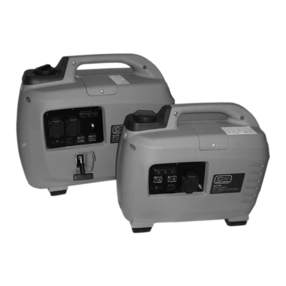
Medusa
Ti-1002 / Ti-2002
Inverter Generator
03951 / 03953
Please read and fully understand the instructions in
this manual before operation. Keep this manual
safe for future reference
1
Advertisement
Table of Contents

Related Manuals for SIP Medusa Ti-1002


Summary of Contents for SIP Medusa Ti-1002
- Page 1 This will allow the recycling of raw materials and help protect the environment. 03951 / 03953 FOR HELP OR ADVISE ON THIS PRODUCT PLEASE CONTACT YOUR DISTRIBUTOR, OR SIP DIRECTLY ON: TEL: 01509500400 EMAIL: sales@sip-group.com or technical@sip-group.com Please read and fully understand the instructions in www.sip-group.com...
-
Page 2: Declaration Of Conformity
2002/95/EC ROHS Directive As Amended By 2005/618/EC, 2005/717/EC, 2005/747/EC, 2006/310/EC, 2006/690/EC, 2008/35/EC, 2008/385/EC And the following harmonised standard(s) EN 12601:2001 EN 55012:2002+A1:2005 EN 61000-6-3:2007 EN 61000-6-1:2007 Signed: …………………………………... Mr P. Ippaso - Director - SIP (Industrial Products) Ltd Date: 20/04/2010. - Page 3 NOTES CONTENTS Page No. Description Contents Safety Instructions Guarantee Technical Specifications Getting To Know Your Generator Operating Instructions Maintenance Exploded Drawing - Ti-1002 Parts List - Ti-1002 Exploded Drawing - Ti-2002 Parts List - Ti-2002 Notes Declaration Of Conformity...
-
Page 4: Safety Instructions
SAFETY INSTRUCTIONS NOTES IMPORTANT: Please read the following instructions carefully, failure to do so could lead to serious personal injury and / or damage to the heater. 1. Before starting or servicing any generator, read and understand all instructions. Fail- ure to follow safety precautions or instructions can cause equipment damage and/or serious personal injury. - Page 5 NOTES SAFETY INSTRUCTIONS….cont 22. If any fuel makes contact with your skin wash with soap and water immediately. 23. If you swallow any fuel, inhale any vapour or allow contact with your eyes, seek medical attention immediately. 24. Be sure to store petrol in clean containers that do not contain water, dirt or rust be- cause this will reduce the life of the engine;...
- Page 6 SAFETY INSTRUCTIONS….cont PARTS LIST….cont Washer M4 PW01-00064 Washer M4 PW01-00064 Flammable: The fuel used to run this generator (unleaded petrol) is highly flammable. Never re-fuel the generator whilst it is still running. Bracket Connector PW01-00177 Bracket Connector PW01-00177 Store un used fuel safely and away from children and in accordance Muffler Shield Left PW01-00178 Muffler Shield Left...
- Page 7 Guarantee: 108-10 Pulse Air Valve Connector PW01-00170 108-12 Pulse Air Valve PW01-00170 These SIP inverter generators are covered by a 12 month parts and labour warranty 108-11 Pulse Air Valve Bracket PW01-00170 108-13 Hex Bolt M6x16 PW01-00170 covering failure due to manufacturers defects. This does not cover failure due to mis-...
-
Page 8: Technical Specifications
TECHNICAL SPECIFICATIONS PARTS LIST….cont 54-13 Filter Tube PW01-00140 66-6 Fuel Pump Cover PW01-00146 Name Medusa Ti-1002 Medusa Ti-2002 54-14 Cross Head Screw M3x8 PW01-00140 66-7 Cross Head Screw M3x12 PW01-00146 Part number 03951 03953 54-15 Filter Case Connector PW01-00140 Clip 7mm... - Page 9 PARTS LIST GETTING TO KNOW YOUR INVERTER GENERATOR Ref. No Description SIP Part No Ref. No. Description SIP Part No. 03951 Ti-1002: Engine PW01-00105 Battery Case PW01-00127 Muffler Seal PW01-00106 Flange Bolt M8x25 PW01-00128 Ignition Coil PW01-00107 Rubber Foot PW01-00129...
-
Page 10: Exploded Drawing
GETTING TO KNOW YOUR INVERTER GENERATOR EXPLODED DRAWING 03953: Ti-2002 12 11 10 Ref. No. Description Ref. No. Description Exhaust Economy Control Switch Choke Recoil Starter Fuel Cap DC Socket Primer Bowl DC Circuit Breaker Fuel Valve AC Socket Maintenance Panel A Low Oil Indicator Engine Switch Pilot / Power Indicator... - Page 11 PARTS LIST OPERATING INSTRUCTIONS Clip 8mm PW01-00022 Exhaust Pipe PW01-00085 Hot Surfaces: Always ensure that the generator is turned off and allowed Fuel Filter PW01-00056 Washer M6 PW01-00086 to fully cool before any refuelling or maintenance procedures are car- Threaded Bolt PW01-00057 Spring Washer M6 PW01-00087...
- Page 12 OPERATING INSTRUCTIONS….cont PARTS LIST Ref. No Description SIP Part No Ref. No. Description SIP Part No. Engine PW01-00001 Fuel Tank Cap PW01-00030 Caution: Be sure oil level is maintained. Failure to do so will invalidate any warranty you may have.
- Page 13 EXPLODED DRAWING OPERATING INSTRUCTIONS….cont Starting the engine: Caution: Never start the engine with any load connected to the gen- erator. Step 1: ⇒ Turn the main engine switch to the on (1) position. Engine Switch 03951 Ti-1002 03953 Ti-2002 Step 2: ⇒...
- Page 14 OPERATING INSTRUCTIONS….cont OPERATING INSTRUCTIONS….cont MAINTENANCE INSTRUCTIONS….cont Step 4 (Ti-1002 only): 1. Remove the fuel tank cap and filter. 2. Clean the filter with solvent, if damaged then replace. ⇒ Open the air vent valve on the fuel cap (Ti-1002 only) 3.
-
Page 15: Maintenance Instructions
MAINTENANCE INSTRUCTIONS OPERATING INSTRUCTIONS….cont Note: When the generator is first started, the overload indicator may light Caution: Always turn off the generator and allow to fully cool before up for a few seconds - This is normal. carrying out any maintenance procedures. Change The Engine Oil (every 30 hours of use). - Page 16 OPERATING INSTRUCTIONS….cont OPERATING INSTRUCTIONS….cont and check that they are functioning correctly. Set the economy switch to off. Check for any blockages restricting airflow, and clear. Start the engine. Restart the engine and reconnect the device once everything is in order. Caution: To reduce the possibility of creating a spark near the battery, Low Oil Indicator: connect the battery charging lead to the battery first and then to the...
Need help?
Do you have a question about the Medusa Ti-1002 and is the answer not in the manual?
Questions and answers