Table of Contents
Advertisement
Quick Links
Advertisement
Table of Contents

Related Manuals for Enpaix EFGS series

Summary of Contents for Enpaix EFGS series
- Page 1 Digital Force Gauge User’s Manual...
-
Page 2: Table Of Contents
Contents 3.4 Printing 1. Introduction 3.5 System Setting 1.1 Overview 4. Communications Ports 1.2 Indicator 4.1 USB/Recharge 1.3 Load Cell 4.2 Multifunction port 1.4 Specifications 5. Maintenance and Calibration 2. Operation 5.1 Charging 2.1 Choose model 5.2 Calibration 2.2 Measuring adapters 6. -
Page 3: Introduction
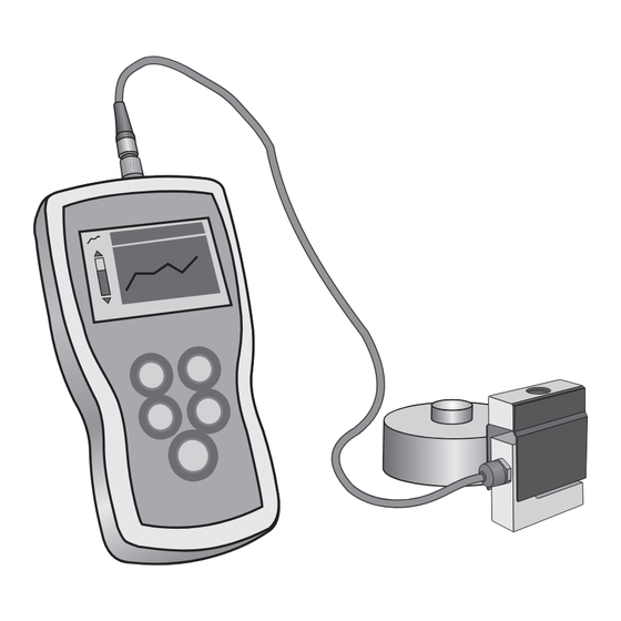
1. Introduction 1.1 Overview The force gauge consists of a force indicator and a load cell. An indicator can be equipped with a few of load cells. Every load cell can be calibrated independently, and indicator can LCD Screen identify them automatically.. Multifunction 1.2 Indicator Port... -
Page 4: Load Cell
1.2.2 LCD Screen ❶ Test mode Track, Peak, Auto Peak, First ❻ ❺ ❷ ❻ Peak ❶ ❶ ❷ Force value ❺ ❸ Analog bar: Indicates current position ❷ in whole capacity. When the bar enters ❸ ❸ the area enclosed by dotted line, means overload. -
Page 5: Specifications
S-beam type Ring type S-beam type Ring type Rated Output(mV / V) 2.0±1 1.5±0.5 Safe Overload(F.S.) 150% 120% Zero Balance(%F.S.) ±2 ±2 Input Impedance(Ω) 410±10 410±10 Non-linearity(%F.S.) Output Impedance(Ω) 0.03 0.05~0.1 350±5 350±5 Hysteresis(%F.S.) 0.03 0.05~0.1 Protection Class IP76 IP76 Temp. -
Page 6: Operation
2. Operation 2.1 Choose model This series has a variety of models can be selected, different models corresponding to different capacity and resolution, as shown in table on back cover of this manual. 2.2 Choose measuring adapters In order to complete the test work convenient, the force gauge equipped with a variety of adapters. Select the appropriate adaptors according to the actual need. -
Page 7: Storage
This series force gauge has 4 kinds of measurement test mode can choose. You can select it by touching under the measure interface, Or can change it in menus (See 3.2.4 Test Mode ). Track: The real time measuring mode, under this mode, press the zero key the force gauge will be cleared (remove tare). -
Page 8: Menus
3 Menus 3.1 Menus Structure The Force Gauge has multi-level menu interface. Table 3-1 Unit Display Mode From Group Display Direction Tolerance Power Off Fig. 3-1 Measurement home Test Mode Backlight screen, Peak Time Key Tone Alarm System Date/Time touch Storage Mode Password “... -
Page 9: Measurement
In number input, touch can increase the number, and touch can change to another digit or item. 3.2 Measurement The Measurement contains six selectable items: Unit, Group,Tolerance, Test mode, Peak Time and Alarm.(Fig, 3-3) 3.2.1 Unit The measuring unit can be selected under this menu. -
Page 10: Memory
The upper limit value must be greater than the lower limit, and both limit value can not be greater than 110% of the rated capacity. See Fig.3-6. 3.2.4 Test Mode Test mode can Fig. 3-9 be selected. There are 4 kinds of mode: Fig. - Page 11 3.3.1 Storage Mode There are two storage mode can be selected, Single and Series. Single: The current value displayed can be saved when touch This mode can be use in all 4 test modes. Series: Continuous storage mode, only Fig. 3-11 in Auto Peak mode is effective.
-
Page 12: Printing
3.3.3 Delete Data Delete selected: Delete data in number range selected. Delete All: Delete all data saved. Before delete data, a warning window will pop up for further confirmation. 3.4 Printing The force gauge can be connected to a printer for printing the report. In Printing menu, you can Print Recent, Print Selected and Print All. -
Page 13: System Setting
3.5 System Setting 3.5.1 Display Mode There are two display modes: Digital and Graphic. The display styles shown as Fig. 1-3 3.5.2 Display Direction LCD display direction can be transformed according to the position of force gauge automatically. Fig. 3-20 You can set it to Obverse or Reverse and not Automatic. - Page 14 mistake or unexpected change. The default System password is“123”. You can change it to your favorite You should enter the old password first, then enter a new one. Fig. 3-24 3.5.8 Key Setting The key is a multifunction key, Fig. 3-27 It can be set as "store the current display value(Storage)"...
-
Page 15: Communications Ports
4 Communications Ports The force gauge have two kinds of port for recharging and communicating with PC and the other equipments. 4.1 USB/Recharge Use this port, you can connect the gauge to the computer for transform data to PC in accordance with USB2.0. Or recharge the internal Ni-MH battery with connecting the recharger. - Page 16 4.2.2 Setpoint Outoput Two setpoint outputs are NPN open collector. The internal circuit of setpoint output is shown as Fig 4-3. Pin7 with Pin6 will be connected when an overload alarm occurs. If Alarm is turned on, Pin7 to Pin6 is connected when the measured value exceed Fig.
-
Page 17: Maintenance And Calibration
5 Maintenance and Calibration 5.1 Charging When the battery are low, the icon “ ” will be displayed. The batteries should be charged immediately. Connect the gauge and the charger use the USB cable, and then connect the charger with AC socket to start charging. It takes about 3~4 hours for fully charging. - Page 18 moment for the force stability. ⑤ Touch to input the stansard force value. ⑥ Touch to enter the next calibration. Touch can interrupt the calibration. When the 5 times calibration had been finished or be interrupted, a confirm ❶ window will pop up to ask for save or not save the calibration. (Fig. 5-3) ❷...
-
Page 19: Connecting Load Cell
6 Connecting Load Cell The force indicator can be connected to the other load cells. Connecting to a plug and setup may be needed when using the load cell not from Capacity Resistance Pin# Description (kN) (kΩ) 6.1 Connection Power + Welding the cable of Output + load cell with the plug. -
Page 20: Appendix
Appendix Packing List Dimension Indicator Load Cell User's Manual Recharge USB Cable Fig. A-2 Fig. A-1... -
Page 21: Warranty Card
Capacity Type 100/0.01 1000/0.1 220/0.05 200/0.05 450/0.1 2000/0.5 500/0.1 1100/0.1 5000/1 10/0.001 10kN 1000/0.1 2250/0.5 10000/1 20kN 20/0.005 4500/1 2000/0.5 10kN 10/0.001 2250/0.5 10000/1 10000/1 20kN 20/0.005 4500/1 2000/0.5 50kN 50/0.01 11k/0.001k 5/0.001 5000/1 100kN 100/0.01 22k/0.005k 10/0.001 200kN 200/0.05 44k/0.01k 20/0.005 DUM413-03-0000EN1507...
Need help?
Do you have a question about the EFGS series and is the answer not in the manual?
Questions and answers