
Related Manuals for Dynamic DX2-REM550

Summary of Contents for Dynamic DX2-REM550
- Page 1 ULTIMATE POWERCHAIR CONTROL SOLUTION DX2-REM550/REM551 INSTALLATION MANUAL From software v2.03 onwards GBK60348: Issue 3...
-
Page 2: About This Manual
Dynamic owns and will retain all trademark rights and Dynamic or its licensors own and will retain all copyright, trade secret and other proprietary rights, in and to the documentation. - Page 3 All materials contained within this manual, in hard-copy or electronic format, are protected by copyright laws and other intellectual property laws. © Copyright 2013 Dynamic Controls. All rights reserved GBK60348: Issue 3...
- Page 4 Acronyms and abbreviations Four Quadrant Advanced Joystick Remote Environmental Control Unit Electromagnetic Compatibility On-Board Programming System Backup Mirror Universal Control Input An industry-standard 3-pin connector; this is used for wheelchair charging. GBK60348: Issue 3...
-
Page 5: Table Of Contents
Contents About this Manual ............2 Introduction to the DX2 AJR ........7 DX2 AJR Operation ..........8 The keypad ................. 8 The Screen ................... 9 2.2.1 Screen Layout ..............9 2.2.2 The Status Bar ..............9 Turning the DX System on and off with the AJR ....11 2.3.1 System Lock .............. - Page 6 4.1.1 System Backup Mirror exceptions ....... 45 4.1.2 SBM Connection Memory ..........46 4.1.3 Remote compatibility list ..........46 4.1.4 Replacing modules other than a DX2 Master Remote or DX2 Power Module.............. 47 Parameter list ................49 4.2.1 AJR User Options (DX Mode) ........55 4.2.2 Added/changed DX System parameters ....
-
Page 7: Introduction To The Dx2 Ajr
The DX2 Advanced Joystick Remote (AJR) is the front-runner in a new generation of DX Modules that sets a new standard for Dynamic and the powerchair industry. The DX2 AJR is a fully DX-compatible Master Remote that offers many new features and enhancements, including: ... -
Page 8: Dx2 Ajr Operation
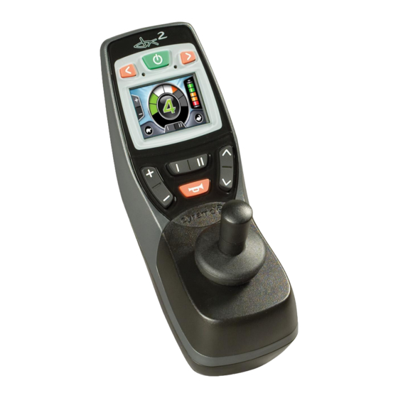
2 DX2 AJR Operation 2.1 The keypad On/Off button Right indicator Left indicator button button (DX2-REM550) (DX2-REM550) Screen Function keys Accessory Mode Drive Profile selection selection Horn Variant Properties DX2-REM550 Colour screen 7 buttons DX2-REM551 Colour screen ... -
Page 9: The Screen
2.2 The Screen 2.2.1 Screen Layout The screen layout varies depending on the selected mode – Drive Mode (left-hand screen above), and Accessory Mode (right-hand screen above). The area at the centre of the screen shows the mode that is currently active. 2.2.2 The Status Bar The status bar is located at the top of the screen. - Page 10 2.2.2.1 The Battery Gauge The Battery Gauge indicates how much battery charge remains. Battery Gauge Meaning Battery full Battery almost full Battery half full, drive towards a charger Battery low, recharge soon Battery almost empty, recharge now Battery empty, recharge immediately The remaining battery capacity does not translate directly to remaining physical range of the powerchair.
-
Page 11: Turning The Dx System On And Off With The Ajr
2.3 Turning the DX System on and off with the AJR To turn on the DX System Press the power button. The AJR will beep twice (if the Mode Change Beep parameter, see 4.2.1.10, is set to ‘Yes’) and the system will start up in Drive Mode (see 2.5.1) with the Drive Profile that has been set with the Power-Up Profile Number parameter (see 4.2.1.13). -
Page 12: Menu Navigation Modes
2.4 Menu Navigation Modes 2.4.1 Standard Mode In Standard Mode the menu navigation is mostly performed with the plus/minus (Drive Profile selection) and up/down (Accessory Mode selection) buttons. Some functions can be accessed directly with other buttons (for example the indicator buttons or the function buttons). -
Page 13: Four-Quadrant (4Q) Mode
2.4.3 Four-Quadrant (4Q) Mode Four-quadrant mode is a joystick-only mode for navigating the menus. All menus are accessible by deflecting the joystick. Each Drive Profile can be set to 4Q Mode or Standard Mode separately. Set the Joystick Only Operation parameter (see 4.2.1.15) to 'Yes' in all Drive Profiles for which 4Q Menu Navigation Mode is desired. -
Page 14: Standard Menu Navigation
2.5 Standard Menu Navigation 2.5.1 Drive Mode - Standard Current Current Maximum Speed Drive Profile Speed Select next Drive Profile Battery Gauge Select previous Drive Profile The operation of the function keys is dependent on the value of the [I II] Function Button parameter (see 4.2.1.3). - Page 15 Button Function Drive Mode Menu Map Left Indicator >2s: Side lights Right Indicator >2s: Hazard lights Function Act.* Speed Pot slower faster Warning + Actuator Side lights Actuator Aux1 Drive Actuator up + down Actuator Aux1 up Actuator Aux1 down Drive Drive Left...
-
Page 16: Accessory Mode - Standard
2.5.2 Accessory Mode – Standard Accessory Modes are available: when the presence of that accessory is detected in the DX System; when the menu of that accessory has been enabled with its corresponding menu enable parameter (see sections 4.2.1.7 to 4.2.1.9). Active Accessory (Actuator Mode shown) Next... -
Page 17: On-Board Programming (Obp) Mode - Standard
2.5.3 On-Board Programming (OBP) Mode – Standard The OBP menu is available when OBP Menu (see 4.2.1.7) has the value 'Yes'. OBP Menu Items Menu Item Icon Screen Brightness Clock adjustment Clock visible (yes/no) The cog, displayed above, indicates the Screen Environment OBP top-level menu item. - Page 18 2.5.3.1 OBP Screen Brightness Exit Exit The function keys change the screen brightness value. Use either the function buttons or joystick left/right to change the screen brightness. Use joystick forward/reverse or the accessory buttons to accept the new setting and return to the main OBP menu.
- Page 19 2.5.3.3 Adjust the clock Active digit Time blinks Exit Cancel Exit Cancel The function keys select an individual digit. Use either the function buttons or joystick left/right to select a different digit. Deflect the joystick forward to increase the value of the digit. ...
-
Page 20: Actuator Mode - Standard
2.5.4 Actuator Mode – Standard Active Actuator Function Next Accessory Mode Previous Accessory Mode The function keys scroll through the available actuator functions. Function Active Function Active Actuator Mode Menu F1 - Tilt F14 - Arm rest Next F2 -Recline F26 - Head Prev . -
Page 21: Lighting Mode - Standard
DX Mode (for the CLAM/TAM) Functions F1 - F5 operate actuators 1 - 5. Function F9 operates actuators 3 + 4 simultaneously. Only the actuators that have been enabled are shown in the menu. If actuator 3 and 4 are both enabled, function 9 is added to the menu automatically. -
Page 22: Ecu1 Mode (Ecu Mouse Control) - Standard
2.5.6 ECU1 Mode (ECU mouse control) – Standard ECU1 Mode gives access to the first 6 channels of an Environmental Control Unit Module (ECU) that has been setup as ECU1. These channels are generally used for mouse or communications control. For access to channels 7 and 8 of ECU1 use the ECU2 menu. -
Page 23: Ecu2 Mode - Standard
2.5.7 ECU2 Mode – Standard ECU2 Mode gives access to channel 7 and 8 of an ECU Module that has been setup as ECU1, and to all 8 channels of an ECU Module that has been setup as ECU2. The 8 channels of ECU2 are numbered 9-16. Selected channel Next Accessory... -
Page 24: Iportal Accessory Mode - Standard
2.5.8 iPortal Accessory Mode – Standard The iPortal accessory screen appears in the menu if "Allow Non-Drive Profile" has been set to YES (Drive Profile 0). This profile uses the input source allocated to Drive Profile 1. The intended use of this mode is for proportional control of iPortal from a joystick source. -
Page 25: Menu Navigation - Home Level
2.6 4Q Menu Navigation - Home Level The menu structure of the 4Q navigation mode starts at the 'Home Level'. The Home Level of the 4Q menu is very similar to the standard Accessory Mode (see 0). the up/down buttons or joystick left/right scrolls through the different accessories; ... -
Page 26: Drive Mode - 4Q
2.6.1 Drive Mode – 4Q Drive Mode starts at the Drive Home Level (see 2.6). Deflect the joystick forward to enter the Drive Profile Selection Mode. In Drive Profile Selection Mode the Drive Profile flashes. Select the desired Drive Profile by deflecting the joystick left/right. ... -
Page 27: Force Sleep Mode - 4Q
2.6.2 Force Sleep Mode – 4Q In addition to the automatic sleep timeout that can be set with the Sleep Mode Enable parameter (see DSM 5.3.9.8), the Force Sleep Mode can put the AJR to sleep immediately. Sleep Mode starts at the Sleep Home Level (see 2.6). ... -
Page 28: On-Board Programming (Obp) Mode - 4Q
2.6.4 On-Board Programming (OBP) Mode – 4Q The OBP menu is available when OBP Menu (see 4.2.1.7) has the value 'Yes'. OBP Menu Items Menu Item Icon Menu Item Icon Screen Brightness Clock adjustment Screen Environment Clock visible (yes/no) (inside/outside) OBP Mode starts at the OBP Home Level (see 2.6). - Page 29 2.6.4.1 OBP Screen Brightness Exit Accept Exit Accept The function key changes the brightness value. 4Q Menu Map Deflect the joystick forward/reverse or use the function More Brightness buttons to change the screen brightness. Exit Exit Deflect the joystick left/right or the accessory buttons Accept Accept to accept the new setting and return to the...
- Page 30 2.6.4.3 Adjust the clock Active digit Time blinks Exit 4Q Mode Cancel Active Select Exit Drive Mode Cancel The function buttons select a different digit. 4Q Menu Map Deflect the joystick right or use the function buttons Change Value to select the active digit.
-
Page 31: Lighting Mode - 4Q
2.6.5 Lighting Mode – 4Q The lighting menu is available when: the CLAM Lighting Enable parameter (see DSM section 6.6.2.1) has the value 'Yes'; a CLAM or lighting module is detected in the system; the Lighting Menu parameter (4.2.1.8) is set to 'Yes'. Lighting Mode starts at the Lighting Home Level (see 2.6). -
Page 32: Actuator Mode - 4Q
2.6.6 Actuator Mode – 4Q The Actuator menu is available when actuators are enabled. Only actuators that have been detected are shown. For a list of possible actuators and their corresponding channels see Actuator Mode – Standard (section 2.5.4). Actuator Mode starts at the Actuator Home Level (see 2.6). ... -
Page 33: Ecu1 Mode (Ecu Mouse Control) - 4Q
2.6.7 ECU1 Mode (ECU mouse control) – 4Q ECU1 Mode gives access to the first 6 channels of an Environmental Control Unit (ECU) Module that has been setup as ECU1. These channels are generally used for mouse or communications control. For access to channels 7 and 8 of ECU1 use the ECU2 menu. -
Page 34: Ecu2 Mode - 4Q
2.6.8 ECU2 Mode – 4Q ECU2 Mode gives access to channel 7 and 8 of an ECU Module that has been setup as ECU1, and to all 8 channels of an ECU Module that has been setup as ECU2. The 8 channels of ECU2 are numbered 9-16. This mode is only available if one of the ECU Menu parameters (see 4.2.1.9) is set to 'Yes' and an ECU Module is detected in the system. -
Page 35: Jack Sockets For External Connections
2.7 Jack sockets for external connections The AJR has three jack sockets for the connection of external switches. UCI 1 On/Off UCI 2 A screw-down cover protects the jack sockets and the DX BUS connectors. When 3 party switches are connected, make sure to route the wiring suitably to exit from the notches in the cover. -
Page 36: Universal Control Inputs (Uci 1/Uci 2)
2.7.2 Universal Control Inputs (UCI 1/UCI 2) The REM55x features two programmable 'UCI' 2-pole jack inputs. Each input can be used to provide access to a single option using a single switch or to provide access to multiple functions by switching different valued resistances across the outputs. There are two modes of operation for each jack input: open circuit and fail-safe. - Page 37 Nominal resistance across UCI input Short Circuit Open Circuit Programmable (Standard 150Ω 300Ω 450 Ω (Switches settings Switch Closed) Open) UCI1 and UCI2: Off No Function No Function No Function No Function No Function UCI1: Drive Up + Drive Down Drive Mode Up Drive Mode Alarm...
- Page 38 2.7.2.1.3 Recommended Switch Configurations The circuits shown below are example open circuit configurations: To access a single function To access multiple functions Note: Multiple single switch and resistor combinations can be used in parallel but the effects of pressing more than one switch at once should be considered. 2.7.2.1.4 Open Circuit Resistance Bands The resistances stated in the...
- Page 39 2.7.2.2 Fail-safe Operation The fail-safe operation option provides additional protection against faults including disconnected jack sockets (open circuit) and damaged switch circuit cables that result in the UCI connections being either open circuit or short-circuit. Failsafe UCI circuits are based on the following circuit. Note that either switch may be omitted if not required.
- Page 40 2.7.2.2.1 Fail-safe settings for Jack Inputs When using any fail-safe UCI option, a Stop function will be activated if the UCI circuit is either open circuit or short circuit. Whenever a UCI Stop function is activated, a warning triangle will be displayed on the LCD in the status bar, as shown left.
-
Page 41: Installation And Testing
3 Installation and testing 3.1 Specifications 3.1.1 Electrical Specifications Parameter Value Operating voltage range 18V – 32V DC (nom. 24V) max 12A RMS continuous, Charger rating limited by DXBUS rating Quiescent current < 0.25mA Off, typically 200mA On 3.1.2 Mechanical Specifications Parameter Value Polycarbonate / PET injection-moulded... -
Page 42: Mounting
3.2 Mounting The mounting of the DX2 AJR is backwards compatible with the SHARK product range. The Remote can be mounted on either side of the wheelchair to accommodate left-handed or right-handed users. Mount the DX2 AJR on a flat plate of 54 mm (2.12") width, or on a tube with an outside diameter between 15 mm (5/8") and 22 mm (7/8”). -
Page 43: Ajr Connection With The Dx System
3.3 AJR connection with the DX System The DX BUS connector sockets are located at the bottom of the AJR. A cover protects the DX BUS sockets and the external switch sockets. After connecting the DX BUS cables, carefully replace the cover and retighten the screw. -
Page 44: Programming The Ajr
4 Programming the AJR Warning: The DX2 AJR is part of the DX System. Read the DX System Manual programming chapter (DSM chapter 7) including all its warnings and notes before reading this chapter. The programming chapter of this AJR manual only describes AJR-specific programming. The XLR programming / charger socket is located at the back of the AJR. -
Page 45: The System Backup Mirror (Sbm)
4.1 The System Backup Mirror (SBM) The DX2 Power Module and the DX2 Master Remote both have a backup copy of all the system parameters. If either the DX2 Master Remote or the DX2 Power Module is replaced, the DX2 Master Remote displays an SBM Selection Sequence to the user to choose which module has the correct backup copy. -
Page 46: Sbm Connection Memory
4.1.3 Remote compatibility list Not all DX2 Remotes accept the programs from other DX2 remotes. Master Remote Compatible Programs DX2-REM550 All REM55x programs*. No REM42x programs. DX2-REM551 All REM55x programs*. No REM42x programs. DX2-REM420 All REM42x programs. No REM55x programs. -
Page 47: Replacing Modules Other Than A Dx2 Master Remote Or Dx2 Power Module
The System Backup Mirror does not look at remote compatibility and will show the SBM Selection Sequence, even if a DX2-REM550 has been replaced with a DX2- REM421, for example. Once an incompatible program has been loaded into the Remote, the system will show Flash Code 12 to indicate that the Remote contains a program that is not compatible. - Page 48 DX-SNP secondary remote Non DX2 Power Modules: Non DX2 Power Modules such as DX-GB will perform an Auto-Download from the Master Remote Non DX2 Master Remotes: If a non-DX2 Master Remote is replaced, the values stored on the NEW Master Remote will overwrite the values stored in other modules. After replacement the chair MUST be re-programmed using the Wizard or HHP.
-
Page 49: Parameter List
4.2 Parameter list Key: Editable at this level (see section 7.1.2.1 of the DX System manual) Viewable at this level Grey Look in the DX System Manual for the description of this parameter Parameter Possible Values Default Lite AJR User Options (DX Mode) ... - Page 50 Parameter Possible Values Default Lite Up + Down (Fail safe) Drive Mode Up + Accessory Mode Accy Up + Accy Down + Alarm + Horn Accy-Drive Up + Accy-Drive Down + Alarm + Horn (Fail safe) Alarm + Emergency Stop Accy Up + Accy Down + ...
- Page 51 Parameter Possible Values Default Lite Lock Enable Yes/No 0 - 10 s Drive Delay at Power-Up (s) Disable OONAPU Faults Yes/No Maximum Profile Number 1 – 5 Allow non-driving profile Yes/No ...
- Page 52 Parameter Possible Values Default Lite Joystick Wake-up from Sleep Yes/No (Enable Joystick Wakeup) Drive Profiles Forward Speed @ Maximum 10 – 100 % Forward Speed @ Minimum 5 –...
- Page 53 Parameter Possible Values Default Lite Neutral to PB Delay 20 – 5000ms 100ms Chair Speed Enable No / Yes Chair Speed 0 - 10 CANH Power Switch No / Yes ...
- Page 54 Parameter Possible Values Default Lite Indicators Enable No / Yes Hazard Lights Enable No / Yes Remember Hazard State No / Yes Remote Control Settings (ARC/RSM) ARC Enable No / Yes ...
-
Page 55: Ajr User Options (Dx Mode)
4.2.1 AJR User Options (DX Mode) 4.2.1.1 Left-Right Mounting Parameter Possible Values Default Lite Drive ^/v Accessory +/- Drive Left-Right Mounting Accessory ^/v Accessory ^/v Drive Defines the function of the plus/minus and up/down buttons. - The plus/minus button selects the Drive Profile; +/- Drive the up/down button selects the accessories. - Page 56 4.2.1.3 [I II] Function Button Parameter Possible Values Default Lite Speed Pot Full Lighting Warning + Hazard Warning + ECU Alarm [I II] Function Button Speed Pot ECU Alarm + Toggle ECU Alarm Warning + Actuator Actuator up+down Two Actuators This parameter assigns the operation of the function button during...
- Page 57 When an actuator function is assigned to one or both of the function keys with one of the parameters: Warning + Actuator, Actuator up + down, or Two Actuators, the user can simultaneously drive the chair and operate the actuator(s). This could be useful, for example, when a user begins a descent on a slope, and without stopping the chair, can recline the back of the chair for balance.
- Page 58 4.2.1.5 Jack Socket Operation Parameter Possible Values Default Lite Drive Up + Drive Down + Alarm + Horn Drive-Accy Up + Drive-Accy Down + Alarm + Horn (Fail safe) Alarm + Drive + Emergency Stop Drive + Alarm + Jack Socket I (UCI-1) ...
- Page 59 This parameter defines the operation of the UCI Jack Socket inputs for the different input resistances. ‘Off’ disables the inputs completely. The Drive-Accy option for UCI 1 will scroll through all available accessories and then return to Drive Mode, with the current Drive Profile selected. See also Universal Control Inputs (UCI 1/UCI 2), section 2.7.2.
- Page 60 4.2.1.8 Lighting Menu Parameter Possible Values Default Lite Lighting Menu Yes/No This parameter can show or hide the Lighting Mode (see section 2.5.5) from the accessory menu list (see section 0). The Lighting menu is present in the accessory list. The Lighting menu is hidden from the accessory list.
- Page 61 4.2.1.11 Reversing Beeper Parameter Possible Values Default Lite Reversing Beeper Yes/No If this parameter has the value 'Yes', the AJR will produce an audible beep once a second while the powerchair drives in reverse. 4.2.1.12 Indicator Auto Cancel Parameter Possible Values Default Lite...
- Page 62 4.2.1.15 Joystick Only Operation Parameter Possible Values Default Lite Joystick Only Operation Yes/No This parameter defines whether the AJR menu is operating in Standard Mode (see 2.4.1) or in Joystick-only Four-Quadrant (4Q) Mode (see 2.4.3). Joystick Only Operation can be set for every Drive Profile separately, including attendant mode.
-
Page 63: Added/Changed Dx System Parameters
4.2.1.18 Mouse Inactivity Timeout Parameter Possible Values Default Lite Mouse Inactivity Timeout 5 – 60 min This parameter is only used in 4Q menu navigation mode (see section 2.4.3), and only during the following menus: iPortal2, ECU1 (2.6.7) and ECU2 (2.6.8). If the user has not moved the joystick out of the neutral location during the time that is set with the Mouse Inactivity Timeout parameter, the menu will exit the current mode and return to the 4Q Home Level. - Page 64 4.2.2.2 Joystick Swap Forward/Reverse Parameter Possible Values Default Lite Joystick Swap Forward/Reverse Yes/No If this parameter is set to 'Yes', the forward and reverse operation of the joystick is swapped. Forward Reverse Left Right Left Right Reverse Forward Set Joystick Swap Forward/Reverse to 'Yes' if a remote is mounted in a reverse orientation.
- Page 65 4.2.2.4 Rotate Joystick 90˚ Parameter Possible Values Default Lite Rotate Joystick 90˚ Yes/No If this parameter is set to 'Yes', the operation of the joystick is rotated by 90°. Forward Right Left Right Forward Reverse Reverse Left Rotate Joystick 90˚...
- Page 66 Profiles as well as smooth Drive Profiles in one wheelchair program. For example a responsive sports profile and a smooth cruising profile. Load Compensation Response LC Response Default (if LC Response Profiled is set to ‘Yes’) (if LC Response Profiled is set to ‘No’) Location: DX2 Master Remote (profiles) Location: DX2-PMA Power Module Set for each Drive Profile separately...
- Page 67 Yes – The DX System slows down or stops the powerchair (depending on the value of Actuator System Missing) if: the DX System cannot detect the actuator system that has been set by Actuator System Type , or the communication with the actuator system is lost.
-
Page 68: Appendices
5 Appendices 5.1 Programming Accessories Dynamic DX Programming Accessories Part Description DC Part # Qty/Unit Wizard Kit – Programming Kit Contains DWIZ-KIT software, cables and DWIZ-ADAPT adapter (no dongle) Wizard – Software Only (CD) DWIZ-SW Wizard Dongles – Parallel port... -
Page 69: Full Menu Maps
5.2 Full Menu Maps 5.2.1 Standard menu navigation GBK60348: Issue 3... -
Page 70: Menu Navigation
5.2.3 4Q menu navigation GBK60348: Issue 3... -
Page 71: Intended Use And Regulatory Statement
5.3 Intended Use and Regulatory Statement Intended Use The DX2-REM55x is a component of a DX system intended to allow powered wheelchair users interaction with the DX System. The DX2-REM55x offers flexibility in integrating compatible input and output devices, as configured and connected, and provides extensive adaptability to meet specific user needs through optimal programmability. -
Page 72: Maintenance
5.4 Maintenance 1. All Dynamic electronic components should be kept free of dust, dirt and liquids. For cleaning the product, use a cloth dampened with warm soapy water. Do not use chemicals, solvents or abrasive cleaners, as this may cause damage to the product. -
Page 73: Safety And Misuse Warnings
5.6 Safety and Misuse Warnings The DX2 AJR is part of the DX System and therefore all safety and misuse warnings that appear in the DX System Manual apply to the DX2 AJR as well. See DSM section 10.4. Additional warnings to be included in the User Manual The following warnings must be passed on to the operator of the vehicle before use of the product. -
Page 74: Electromagnetic Compatibility (Emc)
5.7 Electromagnetic Compatibility (EMC) Dynamic Electronic Controllers have been tested on typical vehicles to confirm compliance with the following appropriate EMC standards: USA: ANSI/RESNA WC/Vol:2 - 1998 Sec 21 Europe: EN12184: 1999 Sec 9.8.1-3 National and international directives require confirmation of compliance on particular vehicles. -
Page 75: Index
6 Index [+ -] [^ v] Button mode ......49, 55 Jack sockets ........... 35 [I II] Function button ......49, 56 Joystick angle compensation ....51, 63 4Q (Four Quadrant) ........4 Joystick only operation ......... 62 4Q menu navigation ........70 Joystick swap forward/reverse ....
Need help?
Do you have a question about the DX2-REM550 and is the answer not in the manual?
Questions and answers