
Summary of Contents for samlexsolar SCC-30AB
- Page 1 30 Amp Owner's Please read this manual before Manual Solar Charge operating your charge controller. Controller SCC-30AB...
-
Page 2: Table Of Contents
INDEX 1. Safety Instructions ....................3 2. General Description of PV / Solar System ............5 3. General information - Batteries ..............15 4. Introduction and Features ................24 5. Construction, Layout and Controls ..............30 6. Installation and Operation ................34 7. -
Page 3: Safety Instructions
SAFETY INSTRUCTIONS Please read these instructions before installing or operating the Charge Controller to prevent personal injury or damage to the Charge Controller. General Installation and wiring compliance • Installation and wiring must comply with the local and National Electrical Codes and must be done by a certified electrician. - Page 4 SAFETY INSTRUCTIONS • Use caution to reduce the risk of dropping a metal tool on the battery. It could spark or short circuit the battery or other electrical parts and could cause an explosion. • Remove metal items like rings, bracelets and watches when working with batteries.
-
Page 5: General Description Of Pv / Solar System
GENERAL DESCRIPTION OF PV / SOLAR SYSTEM What is Photovoltaic (PV)? The word ‘photo-voltaic’ is derived from two different words; the word ‘photos’, from the Greek, meaning light and the word ‘voltaic’ developed from the name of the Italian scientist, Volta, who studied electricity. This explains what a PV system does: it converts light energy from the sun into electrical energy. - Page 6 Charge Controller DC-AC Power Inverter To AC Loads GENERAL DESCRIPTION OF PV / SOLAR SYSTEM Grid-tied PV / Solar System PV/Solar Panel (Module) or Array Battery Fig. 2.2 shows a Block Diagram of a typical Grid-tied PV / Solar System. In this system, the Solar Panels (Modules) / Arrays directly feed to an inverter and the inverter is connected to an Electricity Transmission and Distribution System (referred to as the Electricity Grid) such that the system can draw on the Grid’s reserve capacity in times...
- Page 7 GENERAL DESCRIPTION OF PV / SOLAR SYSTEM PV / Solar Cell 12cm Fig. 2.3. PV / Solar Cell The basic element of a PV System is the photovoltaic (PV) cell, also called a Solar Cell. An example of a PV / Solar Cell made of Mono-crystalline Silicon is shown in Fig. 2.3. This single PV / Solar Cell is like a square but with its four corners missing (it is made this way!).
- Page 8 GENERAL DESCRIPTION OF PV / SOLAR SYSTEM When light enters the PV / Solar Cell, some of the “Photons” (packets of electro- magnetic wave energy) from the light energy are absorbed by the semiconductor atoms. The energy of the absorbed light is transferred to the negatively charged electrons in the atoms of the solar cell.
- Page 9 GENERAL DESCRIPTION OF PV / SOLAR SYSTEM The materials used in PV / Solar Cells have different spectral responses to incident light, and exhibit a varying sensitivity with respect to the absorption of photons at given wavelengths. Each semiconductor material will have an incident radiation threshold frequency, below which no electrons will be subjected to the photovoltaic effect. ...
- Page 10 GENERAL DESCRIPTION OF PV / SOLAR SYSTEM PV Cell Types PV cells are most commonly made of Silicon, and come in two varieties, crystalline and thin-film type, as detailed in Table 2.1 Cell types include Mono-crystalline Silicon, Poly-crystalline Silicon, Amorphous Silicon (a-Si), Gallium Arsenide (GaAs), Copper Indium Diselenide (CuInSe2, „CIS“), Cadmium Telluride, or a combination of two materials in a tandem cell.
- Page 11 GENERAL DESCRIPTION OF PV / SOLAR SYSTEM Cell Module Array Figure 2.5. PV cell, Module and Array The cells are very thin and fragile so they are sandwiched between a transparent front sheet, usually glass, and a backing sheet, usually glass or a type of tough plastic. This protects them from breakage and from the weather.
- Page 12 GENERAL DESCRIPTION OF PV / SOLAR SYSTEM Bypass Diodes As mentioned, PV / Solar cells are wired in series and in parallel to form a PV / Solar Panel (Module). The number of series cells indicates the voltage of the Panel (Module), whereas the number of parallel cells indicates the current.
- Page 13 GENERAL DESCRIPTION OF PV/SOLAR SYSTEM A Current (I) versus Voltage (V) Curve of a PV / Solar Module (“I-V” Curve) shows the possible combinations of its current and voltage outputs. A typical I-V curve for a 12 V Module is shown at Fig. 2.8. The power in a DC electrical circuit is the product of the voltage and the current.
- Page 14 GENERAL DESCRIPTION OF PV/SOLAR SYSTEM The rated power of the PV / Solar Module in Watts (Pmax) is derived from the above values of voltage Vmp and current Imp at this Maximum Power Point (MPP): • Rated power in Watts, Pmax = Vmp X Imp Example of I-V Curve and Ratings of a 12 V PV / Solar Panel Fig.
-
Page 15: General Information - Batteries
GENERAL INFORMATION: BATTERIES Types of Batteries There are several different types of battery chemistry including liquid Lead-Acid, Nickel-Iron (NiFe), Nickel-Cadmium (Ni-Cd), alkaline, and gel-cell. Batteries are either sealed or vented. Simply, there are only two principal types of batteries: starting and deep-cycle. - Page 16 GENERAL INFORMATION: BATTERIES temperature and discharge rate for a high capacity Lead Acid cell. Note that the cell voltage diminishes in direct proportion to the remaining capacity. Fig 3.1 SOC versus Open Circuit voltage The Lead-Acid Batteries A basic equivalent circuit of the Lead-Acid battery is modeled by a voltage source with an equilibrium voltage (V ) in series with an internal resistor (R ) (see Fig 3.2).
- Page 17 GENERAL INFORMATION: BATTERIES Furthermore, it is to consider that these parameters depend also on the current direction (charging or discharge). When the battery were at rest or under open-circuit condition V . When current is drawn from the battery, the voltage will be lower than V .
- Page 18 GENERAL INFORMATION: BATTERIES Fig 3.3: Discharge characteristic curves Figure 3.3 shows the discharge profile of a typical battery type at several constant current rates. The typical end-of-discharge voltage at these discharge rates can also be noticed where the voltage starts to drop steeply. Moreover, the end-of- discharge voltage varies between 1.75-1.9 V, depending on the battery type and the discharge current.
- Page 19 GENERAL INFORMATION: BATTERIES After the gassing voltage is exceeded, voltage stays approximately constant. The whole charging current during this period results in H and O , which is defined as loss. Freezing of electrolyte For applications with low ambient temperature, the Lead-Acid battery must also be protected against freezing of electrolyte.
- Page 20 GENERAL INFORMATION: BATTERIES Figure 3-5: Cycle life as a function of deep of discharge Battery capacity Previously, the storage capacity of a battery is expressed in Ah (Ampere-hours) showing how many hours a certain current can be taken from the charged battery until the battery is discharged, i.e.
- Page 21 GENERAL INFORMATION: BATTERIES Besides, battery capacity is also affected by the temperature: it falls by about 1 % per degree below about 20 °C. Moreover, extreme high temperatures accelerate aging, self-discharge and electrolyte usage. Requirements for solar batteries Typical requirements for the battery to be used in long term storage are: •...
- Page 22 GENERAL INFORMATION: BATTERIES The voltage efficiency is determined by the average discharge voltage (V ) and average charging voltage (V ). V is lower than V particularly by internal resistance of the battery. η (3.5) The overall efficiency (η ) should be as high as possible, to be able to pass the biggest proportion of the energy in the battery, which is generated by the PV generator system, further to consumers.
- Page 23 GENERAL INFORMATION: BATTERIES Since many values are dependent on charge and discharge conditions, they have not been standardized for PV applications and for test purposes until now. Therefore, the comparison between batteries and selection of the most suitable one for each application are not easy.
-
Page 24: Introduction And Features
INTRODUCTION & FEATURES The SCC-30AB is a Series Type of PWM (Pulse Width Modulation) Charge Controller. It is based on an advanced design using a microcontroller for digital accuracy and fully automatic operation. It can be used for 12V or 24V systems for solar charging . The PWM battery charging has been optimized for longer battery life. - Page 25 INTRODUCTION & FEATURES The individual or combined effects of sun peak hour changes, poor charge control and the daily load changes can be potentially damaging to the battery. Cheaper charge control strategies such as simple on/off PV array shedding (Non PWM control) will generally provide the battery with sufficient charging current to complete the Bulk Charge Phase which will return the battery to 80% State of Charge.
- Page 26 Selecting the best method for charging your battery together with a good maintenance program will ensure a healthy battery and long service life. Although the SCC-30AB’s battery charging is fully automatic, the following information is important for getting the best performance from your SCC-30AB Charge Controller and battery.
- Page 27 INTRODUCTION & FEATURES Four Stages of Solar Charging Fig. 4.1 represents the 4 stages of charging used in the SCC-30AB EQUALIZE ABSORPTION BULK FLOAT CHARGING NIGHT NIGHT TIME Fig. 4.1 Solar Charging Stages 1. Bulk Charging: In this stage, the battery will accept all the current provided by the solar array.
- Page 28 INTRODUCTION & FEATURES Equalization Routine equalization cycles are often vital to the performance and life of a battery — particularly in a solar system. During battery discharge, sulfuric acid is consumed and soft lead sulfate crystals form on the plates. If the battery remains in a partially discharged condition, the soft crystals will turn into hard crystals over time.
- Page 29 INTRODUCTION & FEATURES When to Equalize The ideal frequency of equalizations depends on the battery type (Lead Calcium, Lead-Antimony, etc.), the depth of discharging, battery age, temperature, and other factors. One very broad guide is to equalize flooded batteries every 1 to 3 months or every 5 to 10 deep discharges.
-
Page 30: Construction, Layout And Controls
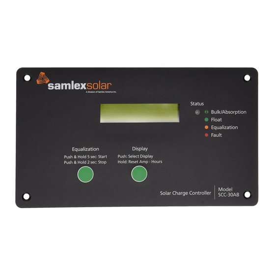
CONSTRUCTION, LAYOUT & CONTROLS General SCC-30AB is designed for flush mounting on a wall / panel. The controls and indications are built on the Front Panel face plate that has 4 countersunk holes for flush mounting (Fig. 5.1). All the electronics, DIP switches for settings, terminal strip... - Page 31 CONSTRUCTION, LAYOUT & CONTROLS Controls & Indications The description and the functions of the controls and indications are given below: Front Panel Charge Status LED Indications LED State Indication Blinking Green Charging is in the state of Bulk or Absorption depending upon the number of blinks as follows: For 12 V Battery For 24 V Battery - 1 Green Blink >...
- Page 32 CONSTRUCTION, LAYOUT & CONTROLS • Display of BULK and FLOAT voltage setting value • Display of Equalization Voltage, Equalization Time and Equalization Interval • Display of heat sink (the front panel metal plate acts as the heat sink) temperature and battery temperature through the optional Battery Temperature Sensor (BTS). * NOTE: As the display is not capable of showing negative values, battery temperature below 0 ºC will not be displayed.
- Page 33 CONSTRUCTION, LAYOUT & CONTROLS Fault Messages The LCD displays might have the following fault messages when SCC-30AB stops operating. Table 5.1. Fault messages Display Description Cause of Fault Alarm: Over Current The current exceeds 45 A Over Current 90 ºC...
-
Page 34: Installation And Operation
/ the panel for flush mounting. The front face plate of the SCC-30AB acts as the heat sink for the heat dissipating components mounted on the PCB at the back of the Front Panel face plate. Hence, please ensure that the Front Panel face plate is not located near a heat generating source and that there is adequate cooling air flow across the face plate to remove the heat dissipated from its surface. - Page 35 2. Make sure the PV currents will not exceed the ratings of the SCC-30AB. 3. The connections to the SCC-30AB terminals are shown in the drawing at Fig. 5.2. A barrier type of Terminal Strip has been provided for connecting the PV array and the battery.
- Page 36 130% of rated current by regulating the current to safe levels. If the current from the solar array exceeds 150%, the controller will interrupt charging. Battery Types: The SCC-30AB’s standard battery charging programs are suitable for a wide range of Lead-Acid battery types. These standard programs are select by DIP...
- Page 37 INSTALLATION & OPERATION Standard Battery Charging Programs The SCC-30AB provides 8 standard battery charging algorithms (programs) that are selected with the DIP Switches. These standard algorithms are suitable for Lead-Acid batteries ranging from sealed (Gel, AGM, maintenance free) to flooded to L-16 cells and Ni-Cd etc.
- Page 38 Manual Equalization The SCC-30AB is shipped with the DIP Switch set for manual equalization only. This is to avoid an unexpected or unwanted automatic equalization. In the Manual Mode, the pushbutton is used to both start and stop a manual equalization. Hold the pushbutton down for 5 seconds to start and 3 seconds to stop an equalization (depending on whether an equalization is in progress or not).
- Page 39 INSTALLATION & OPERATION Temperature Compensated Battery Charging An optional Battery Temperature Sensor (BTS) is available for temperature compensated battery charging. The BTS consists of a temperature sensing probe that is installed on the + battery post. A pair of 10 ft. wires (marked + & -) connect the temperature sensing probe to the 2 terminals marked BTS at the back of the unit.
- Page 40 INSTALLATION & OPERATION Variations in battery temperature can affect charging, battery capacity, and battery life. The greater the range of battery temperatures, the greater the impact on the battery. For example, if the temperature falls to 10°C (50°F) this 15°C (27°F) change in temperature will change the PWM Absorption, equalization and float set points by 0.90V in a 24V system.
-
Page 41: Troubleshooting
If it is unable to maintain its voltage, the battery may be failing. • Measure the PV voltage and the battery voltage at the SCC-30AB terminals. If the voltage at the terminals is the same (within a few tenths of volts) the PV array is charging the battery. - Page 42 TROUBLEShOOTING SYMPTOM 2. BATTERY VOLTAGE IS TOO HIGH • First check the operating conditions to confirm that the voltage is higher than specifications. • Check that the proper battery charging algorithm (program) has been selected by DIP Switches. • Check that all wire connections in the system are correct and tight. •...
-
Page 43: Specifications
SPECIFICATIONS SYSTEM Nominal system voltage 12 VDC or 24 VDC (Selected by DIP Switch) Current rating 30 A Set point accuracy + / - 50 mV Minimum voltage to start the micro- controller, activate protections and guide 9 VDC operation Total self consumption current 50 mA INPUT SIDE (Solar panel / array) -
Page 44: Warranty
5 YEAR Limited Warranty SCC-30AB manufactured by Samlex America, Inc. (the “Warrantor”) is warranted to be free from defects in workmanship and materials under normal use and service. This warranty is in effect for 5 years from the date of purchase by the user (the “Purchaser”). - Page 45 wARRANTY There shall be no responsibility or liability whatsoever on the part of the Warrantor or its employees and representatives for injury to any persons, or damage to person or persons, or damage to property, or loss of income or profit, or any other consequential or resulting damage which may be claimed to have been incurred through the use or sale of the equipment, including any possible failure of malfunction of the equipment, or part thereof.
- Page 46 NOTES...
- Page 47 NOTES...
- Page 48 110-17 Fawcett Rd T: 604 525 3836 e-mail: samlex@samlexamerica.com Coquitlam, B.C. F: 604 525 5221 website: www.samlexamerica.com Canada V3K 6V2 TF: 1 800 561 5885 SCC-30AB_Charge_Controller_Manual_Sep2010...
Need help?
Do you have a question about the SCC-30AB and is the answer not in the manual?
Questions and answers