Table of Contents
Advertisement
Advertisement
Table of Contents

Related Manuals for Marport Catch Sensor


Summary of Contents for Marport Catch Sensor
- Page 1 Catch Sensors Service Manual...
-
Page 3: Table Of Contents
Sensor Configuration............20 Installing Mosa............................20 Connecting the Sensor to Mosa....................21 Calibrating the Catch Sensor......................22 Testing the Catch Sensor on Mosa..................... 24 Catch Explorer Specific Settings....................25 Configuring the Uplink and Down Settings..............25 Configuring the Noise Floor....................27 Calibrating the Sensor for Target Strength Value............. - Page 4 Configuring the Sensor Settings................45 Configuring Data Display on Scala..................... 49 Installation................54 Installing the Sensor on the Trawl..................... 54 Servicing and Maintenance..........57 Interference Check..........................57 Spectrum Analyzer Display....................57 Checking Noise Interference....................57 Charging the Sensor..........................59 Maintenance............................60 Cleaning the Sensor......................60 Maintenance Checklist......................61 Replacing Parts............................
-
Page 5: Legal
Catch Sensors | V1 | Legal Legal Disclaimer Marport endeavour to ensure that all information in this document is correct and fairly stated, but does not accept liability for any errors or omissions. Copyright © 2016-2017 Marport. All Rights reserved. -
Page 6: Introduction And Presentation
There are two types of catch sensors: • Catch sensor: gives you the catch status of the trawl (empty or full), along with depth, water temperature and pitch and roll information. Catch sensors can emit on a single frequency of 40 kHz (Marport, Scanmar) or 70 kHz (Simrad, Wesmar), or on a dual frequency (40 kHz/70 kHz). -
Page 7: Applications
Catch Sensors | V1 | Introduction and Presentation Applications Here are some examples of data received from Catch Explorer and Catch sensors displayed in Scala. Catch Control System Installation You can install several sensors on the codend to better follow the filling processes. It is very useful to determine the amount of fish inside the trawl net: you can prevent damage to fish and increase the security of crew and vessel. - Page 8 Catch Sensors | V1 | Introduction and Presentation Catch Explorer display When the codend is full, you cannot see the sea bottom anymore because fish may block the signal.
- Page 9 Catch Sensors | V1 | Introduction and Presentation Catch sensors display Examples of 3 catch sensors with depth, pitch and roll.
-
Page 10: Safety Guidelines
Install and use this product in accordance with this user manual. Incorrect use of the product may cause damage to the components or void the warranty. Only qualified Marport dealers can do internal sensor maintenance and repairs. Precautions Warning: In case of water ingress in the product, do not charge it: battery may vent or rupture, causing product or physical damage. -
Page 11: Description
Sensors can emit at 2 frequencies: 40kHz (Marport, Scanmar) and 70kHz (Simrad, Wesmar). • Catch hybrid PI firmware is compatible with Simrad PI, Marport and Scanmar systems. Sensors can communicate with Simrad PI and Marport or Scanmar systems at the same time. - Page 12 Product Name Firmware Name Firmware Number Catch hybrid PI FIRM028 Catch hybrid PI with pitch, FIRM029 roll, depth Catch sensor with depth FIRM034 (Simrad PI) Catch compatible Simrad 70 FIRM003 Catch compatible with + Wesmar Simrad and Wesmar only Catch compatible Simrad PI...
-
Page 13: Technical Specifications
Catch Sensors | V1 | Introduction and Presentation Technical Specifications Catch Sensor Uplink frequency 30 to 60 kHz Range to vessel up to 2500 m* Depth range up to 1800 m Pitch angle ±90° Roll angle ±90° (±180° for catch twister) Pitch &... - Page 14 Warranty 2 years (Sensor & Battery) ** *Reference only. Depends on functions enabled. / † Depends on sensor uplink power and options. / ‡ Based on average charging time. / **Marport Standard Marine Limited Warranty Catch Explorer Beamwidths Beamwidths for Uplink pings...
- Page 15 Catch Sensors | V1 | Introduction and Presentation Dimensions | 15...
-
Page 16: Main Parts
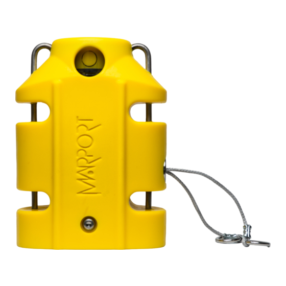
Catch Sensors | V1 | Introduction and Presentation Main Parts External View End cap Side view On the transducer, down sounder is identified with a circle and a A. | 16... - Page 17 Catch Sensors | V1 | Introduction and Presentation Exploded View PCBA Connectors | 17...
-
Page 18: Operational Mode Indicator
Catch Sensors | V1 | Introduction and Presentation Operational Mode Indicator Indicators from the transducer State Situation Operation Charging Charger plug is Batteries are charging. No light. connected. Running Sensor is in water or After an initialization activated with jumper. phase, echo sounder is operating. -
Page 19: Installation Steps
Catch Sensors | V1 | Introduction and Presentation Installation Steps Tip: Click an installation step to jump directly to the corresponding section. Note: You can customize the display of data on Scala at any time. | 19... -
Page 20: Sensor Configuration
Catch Sensors | V1 | Sensor Configuration Sensor Configuration Read this section to learn how to configure catch sensor parameters. Note: This guide refers to the following versions of Mosa: 01.01.01, 01.02.00. If you use another version, the visual interface and options may vary slightly. -
Page 21: Connecting The Sensor To Mosa
Catch Sensors | V1 | Sensor Configuration • Select Terminal from the results. • From the terminal, enter sudo spctl --master-disable. • Press enter. Anywhere option is now displayed in Security & Privacy preferences. Connecting the Sensor to Mosa To configure the sensor, you need to connect it via Bluetooth to Mosa. Procedure 1. -
Page 22: Calibrating The Catch Sensor
What to do next You can now configure the sensor settings. Calibrating the Catch Sensor You need to calibrate the catch sensor to make sure you have correct catch measures. This procedure applies for both Catch Explorer and Catch sensors. Before you begin The sensor is connected to Mosa. - Page 23 Important: For proper operation, do not set the percentage below 65% or above 85%. 4. To calibrate the catch sensor, from the tab Catch, click Catch Calibration. 5. Click Start Calibration. 6. To calibrate the sensor for the empty status: a) Let the cords hang loose.
-
Page 24: Testing The Catch Sensor On Mosa
After a few seconds, the Apply button becomes gray. Measures from Empty Threshold and Full Threshold change. What to do next You can test the catch sensor to check if the empty or full status appear correctly when the cords are pulled. Testing the Catch Sensor on Mosa You need to test the catch sensor to check if the empty/full status works correctly. -
Page 25: Catch Explorer Specific Settings
Catch Sensors | V1 | Sensor Configuration Note: The empty/full status depends on the pull cord triggering offset set in Catch parameters. Catch Explorer Specific Settings You need to set these settings for a Catch Explorer sensor. Configuring the Uplink and Down Settings You can configure different settings for uplink and down soundings. - Page 26 Catch Sensors | V1 | Sensor Configuration • Detection between 20 cm and 2 m, enter 0.1 ms (recommended for Catch Explorer sensors) • Detection above 50 cm, enter 0.4 ms. Note: Ping length is an important setting for the calibration of the sensor.
-
Page 27: Configuring The Noise Floor
Catch Sensors | V1 | Sensor Configuration level when signals travel toward deeper targets. The end result is to compensate sounding attenuation and therefore to show a same target strength for a same target at different depths. For V3 version of sensors: •... -
Page 28: Calibrating The Sensor For Target Strength Value
Catch Sensors | V1 | Sensor Configuration 2. Click the tab Trawl Explorer. 3. From Down Noise Floor Level click Run Measure. The noise floor average, max and min measures are displayed. 4. In Noise floor voltage, enter: • For V2 version, the average measure. •... - Page 29 Catch Sensors | V1 | Sensor Configuration Procedure 1. Set up the following installation. See Appendix B: Examples of Installations for a Target Strength Calibration on page 94. • Water needs to be still. • To hold the ping pong ball, use a very thin fishing line (0.1mm thick). 2.
- Page 30 Catch Sensors | V1 | Sensor Configuration vertical line and drag it to the top of the curve. Press up and down arrows on your keyboard to move it with more precision. 8. From the bottom of the screen, click Calibrate. Note: If the sensor is not correctly placed, you may have an error message asking you to correct the pitch and/or roll angle.
-
Page 31: Canceling The Ringing
Catch Sensors | V1 | Sensor Configuration The sensor sends 1 ping to check if the calibration settings are correct in comparison to the target strength set (e.g. -39 dB). If they are correct, calibration settings are saved. If calibration settings are not correct, check: •... - Page 32 Catch Sensors | V1 | Sensor Configuration Procedure 1. From Mosa, click Menu > Expert Mode and enter the password copernic. 2. From the tab Trawl Explorer, click Ringing Down. 3. Place the sensor in a large tank or in your office and click Emit 10 Ping Down. The sensor emits 10 pings and you can see a curve on the graph.
-
Page 33: Configuring Catch Sensor Telegrams
6. Click Apply. Configuring Catch Sensor Telegrams If you have a Catch sensor (40kHz), you need to configure the telegrams it transmits. This does not apply for Catch Explorer sensors. About this task Telegrams are types of signals sent by the sensor. -
Page 34: Depth
Catch Sensors | V1 | Sensor Configuration Depth Procedure 1. Click the tab Depth. 2. From Depth Boat Code/Channel Code, choose a frequency. 3. From Depth Telegram, choose among the telegrams according to the depth at which you are fishing. They all send data every 3 to 8 sec, but at different depth ranges. Note: The lower the depth range is, the more precise the measures are. -
Page 35: Catch Hybrid Pi
Sensors can communicate with Simrad PI and Marport or Scanmar systems at the same time. Catch data are sent to Simrad PI system and to Marport or Scanmar systems. Depth, temperature, pitch and roll data are sent only to Marport or Scanmar systems. -
Page 36: Configuring The Uplink Power
• High level of 1800 / 43% approx. 30 days interferences • Issues receiving data Catch sensor • Low SNR The more you inrease the uplink Increase if 1800 uplink 3080 / 92% and up power, the shorter power is not enough. -
Page 37: Testing Measures
Catch Sensors | V1 | Sensor Configuration Testing Measures You can test the measures taken by the sensor (e.g. battery level, temperature) to check that there are no faults. Before you begin The sensor is connected to Mosa. Procedure 1. From Mosa, click Menu >... - Page 38 Catch Sensors | V1 | Sensor Configuration 6. Marport offices only: To add the test on the DealerWeb: a) Click Copy to clipboard. b) From the DealerWeb, click Sensors > A1. c) Enter the sensor product serial number in the search box on the right.
-
Page 39: Updating The Sensor
Downloading the Firmware About this task Note: Marport offices only Only Marport offices can download new versions of firmware. Dealerships need to ask their local Marport office to get the firmware. Procedure 1. From a Mozilla Firefox or Google Chrome browser only, go to the DealerWeb page: https://dealerweb.marport.fr/Default.aspx. -
Page 40: Exporting Configuration Settings For Record Keeping
• Or, click Copy to clipboard, then press Cmd + V on a word processor like Microsoft Word to paste the contents. 5. Marport offices only: To add the contents of this file on the DealerWeb: a) Click Copy to clipboard. -
Page 41: Exporting Sensor Configuration For Receiver
Catch Sensors | V1 | Sensor Configuration b) From the DealerWeb, click Sensors > A1. c) Enter the sensor product serial number in the search box on the right. d) From the part Configuration Readings, right-click in the box next to Config Read and select Paste to paste the contents that you copied from Mosa. - Page 42 Catch Sensors | V1 | Sensor Configuration What to do next Adding the Sensor with a Configuration File on page 43 to know how to add the sensor to a receiver with this file. | 42...
-
Page 43: System Configuration And Display
1. Enter your receiver IP address in Firefox web browser to access the system control panel web page. 2. From the left side of the page, click Sensors. 3. Click the tab Add from Marport Sensor Config Utility. 4. Click Browse and select the XML file. | 43... -
Page 44: Adding The Sensor Manually
Catch Sensors | V1 | System Configuration and Display Information about the sensor is displayed. 5. Select a node from the list on the left. Nodes in green are already used. Note: We recommend you to choose nodes between 1 and 6 because they are placed on the codend. -
Page 45: Configuring The Sensor Settings
Note: Sensors with Catch hybrid 70 firmware can be added to Marport, Scanmar, Simrad and Wesmar receivers. They transmit at a frequency around 40kHz for Marport and Scanmar receivers and also at a frequency around 70kHz for Simrad and Wesmar receivers. - Page 46 Catch Sensors | V1 | System Configuration and Display Catch Sensor Note: The options (depth, temperature, etc.) vary according to the firmware installed. Sensor name displayed in Scala and its features. This setting helps detecting the signal of the sensor among other sensor or echosounder signals.
- Page 47 2, 3 or 4 "full" signals from the sensor. PI Catch Sensor Sensor name displayed in Scala and its features. This setting helps detecting the signal of the sensor among other sensor or echosounder signals.
- Page 48 Catch Sensors | V1 | System Configuration and Display Catch Explorer Sensor name displayed in Scala and its features. This setting helps detecting the signal of the sensor among other sensor or echosounder signals. Change only if you have issues receiving data. •...
-
Page 49: Configuring Data Display On Scala
Catch Sensors | V1 | System Configuration and Display Configuring Data Display on Scala You can display on pages in Scala measurements taken by the sensors (e.g. catch status, depth, pitch and roll...). About this task Sensor measurements are displayed in the control panels, under Sensors Data. Data title should be: •... - Page 50 Catch Sensors | V1 | System Configuration and Display 3. To display echogram images of a Catch Explorer: from TE/CATCH in Sensors Data, click + hold Range of Sonar Data and drag it to the page display. Below is an example of an echogram image. When the codend is not totally full, you can see the bottom of the sea.
- Page 51 Catch Sensors | V1 | System Configuration and Display codend and sensor become stable when the trawl begins to fill. The codend can move again when the codend is full. Note: We recommend you to deactivate Draw Bottom Line option. Right-click the echogram to check if it is activated.
- Page 52 Catch Sensors | V1 | System Configuration and Display d) In Alarm Data and Alarm Conditions, enter the following settings: Note: If you have several Catch sensors, you can select other sensors from Sensor/Trawl Part. e) In Alarm Notifications, choose if you want to display a visual notification in the status bar and a sound.
- Page 53 Catch Sensors | V1 | System Configuration and Display 6. To display pitch and roll data, click + hold data for 3 seconds, until a rectangle appears and drag it to a page in the middle of the screen. From Choose new Gauge Type dialog box, select the type of display. You can for example select Dial or Horizon.
-
Page 54: Installation
Sensors can be installed with the pull cords on the side or on the center of the sensor. Pull cords are attached to the net. When the net fills up and the meshes expand, cords are pulled and this triggers the catch sensor. You can install a stabilization board for Catch Explorer sensors. - Page 55 Catch Sensors | V1 | Installation 4. Attach one end of each rubber strap to the pull cords of the sensor, and the other ends to the net. Make sure the pull cords are taut enough to trigger when the net is full, but loose enough not to trigger when the net is empty.
- Page 56 Catch Sensors | V1 | Installation 5. Install several sensors on the codend to better follow the filling processes. The sensors will trigger one by one, according to the amount of fish inside the codend. After a few tows, you can estimate the amount of tonnage of fish that you have depending on whether one, two or three sensors display a full status.
-
Page 57: Servicing And Maintenance
Catch Sensors | V1 | Servicing and Maintenance Servicing and Maintenance Read this section to learn how to maintain catch sensors. Interference Check Spectrum Analyzer Display The following picture explains the main parts of the spectrum analyzer on Scala. Checking Noise Interference You can use the spectrum analyzer to check the noise level of the hydrophones and check if there are no interference. - Page 58 Catch Sensors | V1 | Servicing and Maintenance 3. From the top right corner of the screen, click Spectrum. 4. From the top left corner of the screen, click Start Spectrum. 5. Select the hydrophone you want to test. Only the hydrophones that are switched on are displayed.
-
Page 59: Charging The Sensor
Catch Sensors | V1 | Servicing and Maintenance 12. When you have enough data, click Stop Spectrum. Charging the Sensor Charge the sensor at any battery level with either Marport Basic Sensor Charger or Marport Medusa II Multi-charger. About this task The sensor uses lithium-ion batteries. -
Page 60: Maintenance
(e.g. sounding range, uplink frequency, options). Maintenance Only an approved Marport dealer can access the internal unit. Warranty will become void if anyone other than an approved dealer tries to do internal maintenance duties on the sensor. -
Page 61: Maintenance Checklist
Every 2 years Return the sensor to an approved Marport dealer for inspection and maintenance. Replacing Parts Qualified Marport technicians can remove and replace the following parts if they are damaged. Replacing the Battery Before you begin For this task you need the following tools: •... - Page 62 Catch Sensors | V1 | Servicing and Maintenance Procedure 1. To remove the housing of the sensor: remove the screws on each side of the end cap using a size 6 Allen key, then push the bottle out. 2. Remove the retainer ring around the transducer (yellow part). 3.
- Page 63 Catch Sensors | V1 | Servicing and Maintenance 6. Place the new battery in the internal housing. 7. Connect the new battery to the PCBA. 8. Put tape above both sides of the battery. | 63...
- Page 64 Catch Sensors | V1 | Servicing and Maintenance 9. As a precaution, replace the 2 main o-rings and 2 backup o-rings on the end cap and transducer as illustrated (cross-section). Inspect and fully clean the o-ring grooves. 10. Check that all seals in the bottle are clean and lubricated. Apply lubricant if necessary. 11.
-
Page 65: Replacing The Pull Cords
• 9/64" Allen key • Anti-seize About this task Only qualified Marport technicians can do this task. Procedure 1. Remove the four screws on the pull cord assembly with a 9/64 size Allen key. 2. Remove the cords, spring and magnet from the hole. -
Page 66: Replacing The Catch Magnet
4. Apply anti-seize on the four screw threads, then tighten the screws with the 9/64 size Allen key. What to do next You need to calibrate the new catch sensor. See Calibrating the Catch Sensor on page 22. Replacing the Catch Magnet You can replace the magnet that is part of the pull cord assembly when the magnet is broken. - Page 67 Catch Sensors | V1 | Servicing and Maintenance Procedure 1. Remove the four screws on the pull cord assembly with a 9/64 size Allen key. 2. Remove the cords, spring and magnet from the hole. 3. If the pull-cords are in good condition, only replace the magnet: a) To remove the old magnet, remove the pin between the arms of the magnet using a drift punch or pliers.
-
Page 68: Replacing The Shoulder Bolts
5. Apply anti-seize on the four screw threads, then tighten the screws with the 9/64 size Allen key. What to do next You need to calibrate the new catch sensor. See Calibrating the Catch Sensor on page 22. Replacing the Shoulder Bolts... - Page 69 Catch Sensors | V1 | Servicing and Maintenance 2. Remove the retainer ring around the transducer (yellow part). 3. To remove the black tube around the bottle, place the bottle in a vise or on the ground and pull out the black tube. You have now access to the electronic components.
- Page 70 Catch Sensors | V1 | Servicing and Maintenance 7. Remove the two screws maintaining the end cap with the 1/8" Allen key. 8. Remove the 3 screws maintaining the 3 shoulder bolts with a Philips screwdriver or a 5/64" Allen key (depending on the model of screws that you have). Hold still the outside of the shoulder bolts with a flat head screwdriver while loosening the screws.
- Page 71 Catch Sensors | V1 | Servicing and Maintenance • Red wire: positive charge 15. Put back the end cap and screw with the 1/8" Allen key (torque at 15 in-lbs / 2 N-m). 16. Put back into place the PCBA and secure it with the retainers. 17.
-
Page 72: Replacing The Temperature Sensor
• 1.5 mm Allen key • 1/8" Allen key • 22 mm wrench • Tweezers • Wire stripper • Crimping tool • O-ring lubricant • Loctite 425 About this task Only qualified Marport technicians can do this task. | 72... - Page 73 Catch Sensors | V1 | Servicing and Maintenance Procedure 1. To remove the housing of the sensor: remove the screws on each side of the end cap using a size 6 Allen key, then push the bottle out. 2. Remove the retainer ring around the transducer (yellow part). 3.
- Page 74 Catch Sensors | V1 | Servicing and Maintenance 6. Disconnect the pressure and temperature connector from the PCBA and remove the temperature sensor cables (2 black and 2 white). 7. Remove the PCBA to get access to the back of the end cap: a) Remove the four screws holding the retainers on each side of the PCBA with a 1.5 mm Allen key.
- Page 75 Catch Sensors | V1 | Servicing and Maintenance 9. Using the 22 mm wrench, remove the temperature sensor and its cables. 10. Remove the o-ring seals placed at the temperature sensor location with tweezers. 11. Fully clean the surface and hole of debris (with a swab or Q-tip) and inspect the surface for burrs or pitting.
- Page 76 Catch Sensors | V1 | Servicing and Maintenance 16. Replace the protective tape. 17. As a precaution, replace the 2 main o-rings and 2 backup o-rings on the end cap and transducer as illustrated (cross-section). Inspect and fully clean the o-ring grooves. 18.
-
Page 77: Replacing The Pressure Sensor
• 1.5 mm Allen key • 1/8" Allen key • Flat screwdriver size 8 to 10 • Tweezers • Wire stripper • Crimping tool • O-ring lubricant • Loctite 425 About this task Only qualified Marport technicians can do this task. | 77... - Page 78 Catch Sensors | V1 | Servicing and Maintenance Procedure 1. To remove the housing of the sensor: remove the screws on each side of the end cap using a size 6 Allen key, then push the bottle out. 2. Remove the retainer ring around the transducer (yellow part). 3.
- Page 79 Catch Sensors | V1 | Servicing and Maintenance 6. Disconnect the pressure and temperature connector from the PCBA and remove the pressure sensor cables (1 red, yellow, green and 2 black). 7. Remove the PCBA to get access to the back of the end cap: a) Remove the four screws holding the retainers on each side of the PCBA with a 1.5 mm Allen key.
- Page 80 Catch Sensors | V1 | Servicing and Maintenance 9. With the flat screwdriver, remove the screw above the pressure sensor. 10. Remove the components from the hole of the end cap: a) Remove the spring and washer (if applicable) with tweezers. b) From the inside, push the pressure sensor and its cables out with a small screwdriver or Allen key.
- Page 81 Catch Sensors | V1 | Servicing and Maintenance b) First, install the components in the following order (if no pressure-relief spring, there is no washer): c) Insert the install tool into the hole in the end cap and tighten with the flat screwdriver to set the pressure sensor in place.
- Page 82 Catch Sensors | V1 | Servicing and Maintenance g) Put the pressure sensor cables through the hole in the internal housing and connect them to the white connector in the following order (view of side with clips upward): h) Put back the end cap and screw with the 1/8" Allen key (torque at 15 in-lbs / 2 N- i) Connect the white connector to the PCBA.
-
Page 83: Updating The Depth Coefficients
"UP" writing, and must be aligned to the round opening in the housing. Updating the Depth Coefficients About this task Note: Marport offices only Procedure 1. Go to the DealerWeb page: https://dealerweb.marport.fr/Default.aspx and select Sensors >... -
Page 84: Replacing The Transducer
• Needle nose pliers • O-ring lubricant About this task Only qualified Marport technicians can do this task. Procedure 1. To remove the housing of the sensor: remove the screws on each side of the end cap using a size 6 Allen key, then push the bottle out. - Page 85 Catch Sensors | V1 | Servicing and Maintenance 2. Remove the retainer ring around the transducer (yellow part). 3. To remove the black tube around the bottle, place the bottle in a vise or on the ground and pull out the black tube. You have now access to the electronic components.
- Page 86 Catch Sensors | V1 | Servicing and Maintenance 9. Install the new transducer: the uplink LED, up and uplink cables must go through the hole in the internal housing. 10. With an Allen key, screw back the transducer. 11. Connect the uplink LED cable to the uplink LED connector. 12.
- Page 87 Catch Sensors | V1 | Servicing and Maintenance 15. As a precaution, replace the 2 main o-rings and 2 backup o-rings on the end cap and transducer as illustrated (cross-section). Inspect and fully clean the o-ring grooves. 16. Check that all seals in the bottle are clean and lubricated. Apply lubricant if necessary. 17.
-
Page 88: Troubleshooting
3. Check the noise on the spectrum (see Checking Noise Interference on page 57). If the frequency where the sensor is placed is too noisy, change for a less noisy frequency: a. Catch sensor: see Configuring Catch Sensor Telegrams on page 33 b. Catch Explorer: see... -
Page 89: Echogram Is Fixed And Blue
Catch Sensors | V1 | Servicing and Maintenance e. From NBTE Echograms Filter select Echosounder and Interference Reduction Medium or High. Echogram is fixed and blue The echogram displayed in Scala is completely blue. There is no yellow line moving on top of the echogram, which means that no sonar data is received. -
Page 90: Catch Status Remains Full Or Empty
Catch status remains full or empty Catch status displayed on Scala remains blocked on full or empty status. The catch magnet may be broken. 1. From Mosa, test the catch sensor (see Testing the Catch Sensor on Mosa on page 24). -
Page 91: Support Contact
Catch Sensors | V1 | Servicing and Maintenance Support Contact You can contact your local dealer if you need maintenance on your Marport products. You can also ask us at the following contact details: FRANCE ICELAND Marport France SAS Marport EHF... -
Page 92: Appendix A: Frequency Plan
You can create a table with a list of frequencies and complete it when you add sensors. Type of sensor Interval between frequencies PRP (e.g. Catch sensor, Trawl Speed, Door 100 Hz Spread sensor...) NBTE (e.g. Speed Explorer, Trawl Explorer,... - Page 93 Catch Sensors | V1 | Appendix A: Frequency Plan Boat Codes This list shows the standard frequencies for PRP telegrams. When you configure boat codes, make sure to respect the correct interval between frequencies (see table above). | 93...
-
Page 94: Appendix B: Examples Of Installations For A Target Strength Calibration
Catch Sensors | V1 | Appendix B: Examples of Installations for a Target Strength Calibration Appendix B: Examples of Installations for a Target Strength Calibration Support for sensor Figure 1: Example of support Figure 2: Example of support | 94... - Page 95 Catch Sensors | V1 | Appendix B: Examples of Installations for a Target Strength Calibration Ping pong ball Figure 3: Fishing line passes through the ball and is fixed with glue. Figure 4: Example of installation with counterweights. | 95...
- Page 96 Catch Sensors | V1 | Appendix B: Examples of Installations for a Target Strength Calibration | 96...
-
Page 97: Index
Hybrid 70 Configuration A1 board Firmware Frequency Telegrams Hybrid PI Battery life Configuration Boat code Firmware Frequency Telegrams Calibration Catch sensor Installation examples Indicators Target Strength Installation Catch alert Catch mode Catch status Blocked LEDs Display Threshold Channel code Charger... - Page 98 Index | 98 Pulse length Range Receiver Adding sensor Compatible versions Configuration file Web page Replacing Battery Magnet Pressure sensor Pull cords Shoulder bolts Transducer Ringing cancellation Scala display Sounding Settings Spectrum System requirements Technical specifications Telegram Temperature sensor Trawl Trawl opening TVG (Time Variable Gain) Uplink power...
Need help?
Do you have a question about the Catch Sensor and is the answer not in the manual?
Questions and answers