Table of Contents
Troubleshooting

Summary of Contents for ESA Corona CAD
- Page 1 ® ® Corona Detector ®Plus ® Corona Detector Operating & Maintenance Manual ESA Biosciences, Inc. 22 Alpha Road Chelmsford, MA 01824-4171 U.S.A. Telephone: (978) 250-7000 Fax: (978) 250-7090 www.esainc.com P/N 70-6258 Rev. G...
- Page 2 US: 5,098,657; 5,374,396, 6,544,484 and 6,568,245. © 2004, 2005, 2006, 2007, 2008 ESA Biosciences, Inc. All rights reserved. No part of this manual may be reproduced or transmitted in any form or by any means without the written permission of ESA Biosciences, Inc.
- Page 3 WARRANTY A. ESA Biosciences, Inc. (“Seller”) warrants to Buyer that each product manufactured by Seller will be free from defects in material and workmanship in normal use from the date of delivery to Buyer as the original purchaser, for the following periods: instruments and equipment-one year;...
- Page 4 E. With respect to products sold to Buyer but not manufactured or, in the case of software, not developed by Seller, SELLER MAKES NO WARRANTY OF ANY KIND, EXPRESS OR IMPLIED, INCLUDING, WITHOUT LIMITATION, ANY WARRANTY OF MERCHANTABILITY OR FITNESS FOR A PARTICULAR PURPOSE, but Seller will make available to Buyer, to the extent permitted by law and relevant contracts, the warranties of the manufacturer of the relevant product or the developer of the software.
-
Page 5: Safety/Operating Symbols
SAFETY/OPERATING SYMBOLS The following symbols appearing on the unit or in the manual are defined as follows: This symbol on the instrument indicates that the user should refer to the operating manual before attempting to connect the power/interface cables and operate the system. This symbol on the back of the instrument indicates a functional earth terminal. -
Page 6: Warnings And Safety Precautions
+99% pure nitrogen (60- 125PSI; max flow 4 L/min) (70-6003). All nitrogen gas shall be preconditioned using the ESA Gas Conditioning Module (70-8285). 3) Exhaust gases must be vented to an appropriate hood or gas collection device, and NEVER vented directly into the laboratory. - Page 7 4) The drain tubing must be properly connected to both the detector and the waste bottle. The drain tubing must be straight without kinks, dips or loops (i.e., areas where fluid can accumulate). Any of these may lead to flooding of the detector.
- Page 8 Lower flow rates may lead to aberrant chromatography and noise. If the Corona CAD detector is to be used in a system where flow is split between it and other detectors, make sure that the flow rate to the Corona CAD detector is between 0.2-2.0 mL/min.
- Page 9 5 minutes later. Finally, turn off the detector. DO NOT leave the detector exposed to either acidic or basic mobile phases. If the equipment is used in a manner not specified by ESA Biosciences, the protection provided by the equipment may be impaired.
-
Page 10: Important Operating Considerations
These devices can usually be obtained from sources that carry computer supplies. If you have any questions concerning this, please contact the ESA Service Department or its Representative. NOTE: A larger capacity for the UPS device is needed if the entire HPLC system is to be covered by this UPS device. - Page 11 RFI. However, it is still possible that a strong emitter of RFI could result in interference with the Corona CAD detector. Therefore, the detector should not be placed close to other instruments or machinery that could emit excessive RFI or magnetic fields such as refrigerators, fume hoods, radio transmitter antennae, NMR instruments, etc.
- Page 12 If the (Optional) Thermal Organizer Module is employed to Control the Temperature, Allow Sufficient Time for Thermal Equilibrium The time required to reach thermal equilibrium depends on the selected temperature and the ambient temperature. The user should ensure that thermal equilibrium has occurred before performing analytical separations.
-
Page 13: Do's And Don'ts
• Use mobile phase of pH < 7.5 whenever possible. • Use gas pressure of 35 +/- 1 psi, as provided by the ESA Gas Conditioning Module (70-8285). • Use an in-line filter between the column and detector. •... - Page 14 Formic Acid 3.75 2.8-4.8 Ammonium Formate 3.75 2.8-4.8 Acetic Acid 4.76 3.8-5.8 Ammonium Acetate 4.76 3.8-5.8 *Not all inclusive. Some Corona CAD Detector-Compatible Volatile Mobile Phase Constituents Plus ® ® ® ® Corona and Corona Detectors Operating and Maintenance Manual...
-
Page 15: Table Of Contents
2.4.1.9 Setting up Corona Plus Nebulizer Heater ........2-15 Test Protocol......................2-16 2.5.1 Role of the Test Protocol................2-16 2.5.2 Setup......................2-16 2.5.3 Protocol ...................... 2-17 ESA Biosciences Corona CAD Detector Test Worksheet ........2-20 Plus ® ® ® ® Corona... - Page 16 2.10 Making Electrical Connections................2-24 2.10.1 Description of the Rear Panel of the Detector..........2-24 2.10.2 Interfacing to the ESA Model 584 Solvent Delivery Module....... 2-27 2.10.3 Interfacing to other Solvent Delivery Modules..........2-28 2.11 Mobile Phase Formulation ..................2-29 2.11.1 Supplies .....................
- Page 17 The System Screens....................3-18 3.6.1 Role of the System Screens............... 3-18 3.6.2 RS232 Setup Screen ................. 3-18 3.6.3 Deleting Methods Screen................3-19 3.6.4 Event Marks Screen................... 3-20 3.6.5 Date & Time Setup Screen ................ 3-21 3.6.6 Remote Screen ..................3-21 3.6.7 Inputs Screen .....................
- Page 18 5.3.2 Changing the Line Fuses ................5-7 5.3.3 Replacing the Gas Filters................5-8 Cleaning the Detector ....................5-9 5.4.1 Cleaning the Corona Detector Unit .............. 5-9 5.4.2 Cleaning the Corona Detector Organizer and Thermal Organizer....5-9 Establishing a System Log ..................5-10 General Troubleshooting Approach ...............
- Page 19 Test Standards and Guard Column .................B-2 Nitrogen Gas Supply....................B-2 APPENDIX C: ORGANIZER AND THERMAL ORGANIZER Overview ........................C-1 Unpacking the Organizer ..................C-1 Installing the Corona Organizer Module ..............C-3 C.3.1 General Information ..................C-3 C.3.2 Removing the Organizer Chassis Plate ............C-5 C.3.3 Installing the Pulse Damper .................C-5 C.3.4 Installing a Rheodyne Manual Sample Injector Valve........C-6 C.3.5 Installing the In-line Filter ................C-7 C.3.6 Installing the Column Holder ................C-7...
- Page 20 This page intentionally left blank. Plus ® ® ® ® xviii Corona and Corona Detectors Operating and Maintenance Manual...
-
Page 21: Chapter 1: Introduction
CHAPTER 1 INTRODUCTION Overview of the Corona CAD Detectors Plus ® ® ® ® The ESA Biosciences Corona and Corona Detectors (Figure 1-1), are universal detectors that are designed to measure non-volatile and some semi- volatile analytes in the eluent from a high performance liquid chromatographic Plus (HPLC) system. -
Page 22: Features Of The Corona And Corona Plus Detectors
Chapter 1 Plus Features of the Corona and Corona Detectors • Reliable and simple to operate. • Universal detection of nonvolatile and many semi-volatile analytes. • Four orders of magnitude dynamic range (nonlinear). • Low ng lower limits of detection. •... -
Page 23: The Detector Module Includes
Introduction Description of the Detector Plus The ESA Biosciences Corona and Corona detectors are self-contained units (Figure 1-1), and include the electronics, detector assembly, and all controls. Specifications can be found in Appendix A. 1.4.1 The Detector Module Includes: The User Interface The detector user interface includes a display panel and a keypad (Figure 1-2). -
Page 24: Corona Detector Organizer Modules
Chapter 1 1.4.2 Corona Detector Organizer Modules A Thermal Organizer Assembly (Part Number 70-5499TA) and an unheated Organizer Module (Part Number 70-5499) are available as options to contain the column, manual injector, in-line filters and related fluidics. These modules can be fitted on top of the detector. -
Page 25: Component Location
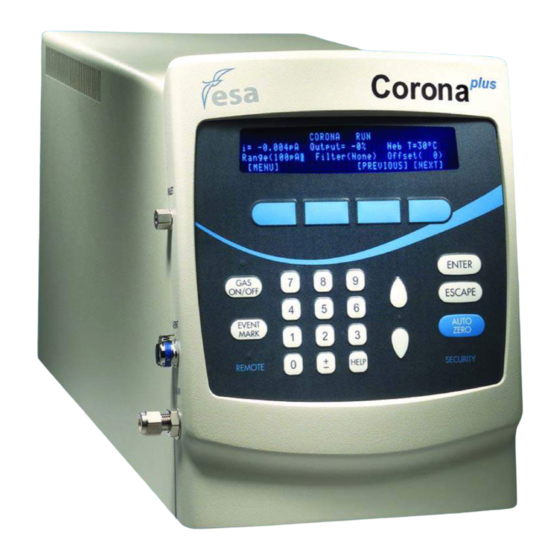
Remote Security “Remote” Indicator “Security” Indicator Numeric Keypad Scroll Up/Down and “Help” Button Keys Active Key Indicator Figure 1-2: Front of the Corona CAD and Plus Corona CAD Detectors Plus ® ® ® ® Corona and Corona Detectors Operating and Maintenance Manual... - Page 26 Chapter 1 HPLC Inlet 11.5“ (28.6 cm) Vent Drain 20.5“ (52.5 cm) 9“ (23 cm) Figure 1-3: Front Left Side of Detector Plus ® ® ® ® Corona and Corona Detectors Operating and Maintenance Manual...
- Page 27 Introduction Logic Module Gas Module Power Module Thermal Organizer Ground Control Thermal RS232 Organizer Power Filter Module Signal Out Brackets Fuse Filter Module Connections Power Line On/Off Switch Gas Inlet Gas Exhaust I/O Connections Figure 1-4: Rear of the Detector Plus ®...
-
Page 28: Mode Of Operation Of The Detector
Chapter 1 Pump Off Gas Off Autozero Strt Figure 1-5: Close-Up of I/O Connections Mode of Operation of the Detector The Corona detector is a mass sensitive detector that can respond to essentially all non-volatile and some semi-volatile compounds in the sample that are eluted from the column. - Page 29 Introduction Evaporation of the Solvent from the Aerosol - the remaining aerosol droplets are directed into the drying tube where the solvent is completely evaporated. Since the droplets are very small, they evaporate very quickly. The remaining analyte particles are then directed into the corona region of the detector. Charging of the Solid Particles - before the particles can be detected they must be electrically charged.
-
Page 30: Additional Information
Chapter 1 Figure 1-7: Schematic Overview of the Detector Additional Information A detailed discussion of the use of aerosol charging detection in HPLC is presented R.W. Dixon and D.S. Peterson, Development and Testing of a Detection Method for Liquid Chromatography Based on Aerosol Charging, Anal. Chem. 2002, 74, 2930-2937. -
Page 31: Support From Esa
ESA also offers instrument qualification services including Installation Qualification (IQ) and Operational Qualification (OQ). Performance Qualification (PQ) is performed by the customer, unless the Corona CAD detector is part of a complete ESA HPLC system. For details, please contact ESA or your local representative. -
Page 32: Frequently Asked Questions
The efficiency of particle charging and detection (i.e. Corona CAD detection) has been shown to be much more uniform with particle size. Also, our results suggest that Corona CAD detector response is not as dependent on the physical (e.g., crystalline) characteristics of the aerosol. - Page 34 Question: Can the Corona CAD detector be used with SFC? Answer: We have not tried CAD with SFC at ESA Biosciences, but we do have customers that use this approach. Question: Does the corona description mean that gas is floating in the form of a ring around the platinum wire? What sort of high mobility particles are removed by the ion trap? Where do the negatively charged particles go? If you create a positive charge don’t you create a negative charge as...
-
Page 35: Chapter 2 Installation
• Installing the Detector (Section 2.4) • Test Protocol (Section 2.5 • ESA Biosciences Corona CAD Detector Test Worksheet (Section 2.6) • General Operations (Section 2.7) • Other Detector Configurations (Section 2.8) • Setting up the Thermal Organizer (Section 2.9) •... - Page 36 Chapter 2 • Nitrogen gas must be available. A supply of nitrogen gas is required for the operation of the detector. The gas must be supplied at 35.0 +/- 0.1 psi (2.4 bar) and must be 99.99% pure. WARNING: The nitrogen gas source must not be oil-pumped as oil in the gas stream can clog the detectors in-line filters and may damage the detector itself.
-
Page 37: Power Requirements
Installation • Only use appropriate mobile phases: o If PEEK components are present in the HPLC system DO NOT use: dichloroacetic acid; acetone; tetrahydrofuran (THF); dichloromethane; chloroform; dimethylsulfoxide (DMSO). Although unlikely to be used with the Corona detector, PEEK is not compatible with strong acids such as concentrated sulfuric acid and concentrated nitric acid. -
Page 38: Space Requirements
The weight of the detector is: 22lbs (10kg) The space requirements for the entire HPLC system depends on the configuration of the system. Figure 2-1 shows the space requirements for a typical ESA HPLC Corona detector system. Figure 2-1: Approximate Dimensions for a Corona Detector System Plus ®... -
Page 39: Nebulization Gas
NOTE: See Appendix B for a list of recommended supplies and spare parts. Carefully inspect the shipping carton(s) and all components. If any parts are missing, call ESA's Customer Service Department and indicate the missing items via the part numbers. Plus ®... -
Page 40: Installing The Detector
WARNING: If there is any evidence that the Corona detector unit has been damaged in shipping, do not install or power on the unit. Immediately contact ESA [(800) 275-0102, (978) 250-7000] or its representative for advice. NOTE: The shipping carton should be retained as it can be used if it becomes necessary to transport the detector. -
Page 41: Power Source
Fuse Power Line On/Off Switch Figure 2-2: Rear Panel - Corona CAD Detector NOTE: The detector must be connected to an electrical outlet that shares a common ground with other components of the chromatographic system (e.g., pump, autosampler computers, etc.). -
Page 42: Gas Source
Chapter 2 2.4.1.3 Gas Source a) Connect the nitrogen source to the gas inlet of the ESA Gas Conditioning Module (P/N 70-8285) using the “quick connection” ¼” ID connection. b) Connect outlet of ESA Gas Conditioning Module to the gas inlet (Figure 2- 3), using a “quick connection”... -
Page 43: Exhaust
Installation 2.4.1.4 Exhaust Connect the gas outlet, located on the back of the detector (Figure 2-3), to a fume hood or other venting device with the vent tube supplied. Connect one end of the larger diameter single tubing to the Exhaust Outlet quick connect fitting on the back panel of the detector and connect the other end to a fume hood or vent. - Page 44 Chapter 2 To attach the Drain/Vent Tubing assembly: a) Connect the Vent tubing to the quick connect fitting located on the bottom front left portion of the detector. This is a quick connect fitting which simply latches when the fitting is pushed in (Figure 2-6). b) Connect the Drain tubing (end with SS fitting) to the compression fitting located on the bottom front left portion of the detector.
- Page 45 Installation c) Using the tubing cutter (Part Number 70-7112) from the Drain/Vent kit, cut both the drain and vent tubing to a length (between the detector and waste bottle) where there are no dips, kinks or loops. Cut the drain tubing 4" longer than the vent tubing.
- Page 46 Chapter 2 f) Place the waste bottle in secondary containment in a secure location below the detector (Figure 2-9). Make sure that the cap is tightened to prevent any gas leaks. The waste bottle is a closed system under a slight pressure and has a pressure relief valve on the cap in the event that the bottle becomes over- pressurized (e.g., if exhaust is blocked).
-
Page 47: Hplc System
Installation Figure 2-9: Correct Setup of Drain Tubing 2.4.1.6 HPLC System NOTE: In order to achieve maximum detector performance, a validated, pre conditioned HPLC system should be used. Put the C18 guard cartridge (P/N 88-12307) in the guard column holder (P/N 88- 12414). - Page 48 Chapter 2 WARNING: Failure to properly condition the guard column can result in varying background, high noise or signal spiking. Connect the outlet of the autosampler to the inlet side of the guard column holder. The autosampler, column holder and detector tubing connections should use 0.005" PEEK tubing (Red) that is as short as possible.
-
Page 49: Usb Connections
CD’s provided. ® Agilent – For use with Agilent ChemStation (Version B.02.01 (SR1) or later) using ESA ChemStation Driver (P/N 70-7102). See driver technical note for Versions B.03 of higher. ® ESA "Elite" – For use with EZChrom™ Elite for ESA Data Systems (Version 3.2 or... -
Page 50: Test Protocol
If problems are observed, contact ESA Biosciences or its representative. To assist the service engineer, please fax the worksheet to ESA Biosciences’ Service Department - Fax (978) 250-7092 or your local representative to describe the problem and assist in the resolution of the problem. -
Page 51: Protocol
Installation Note a typical method has the following characteristics: Mobile Phase Flow Rate – 1.0mL/min Column Temperature – ambient Injection Volume – 10µl Run Time – 2.0 minutes 2.5.3 Protocol CAUTION: Make certain that the waste bottle is emptied on a routine basis. - Page 52 Using the application in preview mode, turn on the detector. f) Confirm the gas pressure is 35.0 psi +/- 0.1 psi. If required, adjust the gas pressure using the adjustment knob on the ESA External Gas Conditioning Module (P/N 8285) so that the pressure reads 35.0 psi +/- 0.1 psi.
- Page 53 NOTE: This is only intended to be a preliminary test that the Corona detector is working properly. A more comprehensive Validation Test is available from ESA, or can be created using the standards included with your instrument. Congratulations, your installation of the Corona Detector is complete! Plus ®...
-
Page 54: Esa Biosciences Corona Cad Detector Test Worksheet
Chapter 2 ESA Biosciences Corona CAD Detector Test Worksheet GENERAL INFORMATION Organization: Operator: Address: Phone Number: Fax Number: Email Address: Detector Unit S/N: Date: Software Version: A) Startup Information If there is an error message on the display when the unit is powered up, please indicate. -
Page 55: General Operations
Installation General Operations 2.7.1 Turning Off The Corona Detector Turn off the pump. Allow the gas to flow for at least 5 minutes. Return to the main menu, if in run mode, then press the “Gas Off” switch on the front panel. -
Page 56: Storing The Corona Detector
Chapter 2 2.7.3 Storing The Corona Detector If the detector is not to be used for a few days it should remain connected to the HPLC system. Keep the gas and mobile phase flows off. Remember to check the level of fluid in the waste bottle and empty if needed. If the detector is not to be used for extended periods, then it is probably best to remove it from the HPLC system. -
Page 57: Setting Up The Thermal Organizer
Installation NOTE: Be sure to remove the extra length of tubing before reconnecting the Corona detector to the splitter output. Setting up the Thermal Organizer If a thermal organizer is to be used, connect it using the Y cable (Part Number 70- 5595). -
Page 58: Making Electrical Connections
Filter Module Signal Out Brackets Fuse Filter Module Connections Power Line On/Off Switch Gas Inlet Gas Exhaust I/O Connections Figure 2-16: Rear Panel - Corona CAD Detector Plus ® ® ® ® 2-24 Corona and Corona Detectors Operating and Maintenance Manual... - Page 59 Installation The terminals on the rear panel of the Corona detector are used as follows: • Thermal Organizer Control - If a Thermal Organizer Module (Part Number 70-5499TA) is installed, the Y cable (Part Number 70-5595) is connected to the Thermal Organizer Control socket on the Logic Module and the Thermal Organizer Power connector on the Power Supply Module of the Corona detector while the single cable end is connected to the Thermal Organizer.
- Page 60 Chapter 2 When the output contact closures are used, there is no polarity (plus “+” or minus “-”). The third wire on the cable (the ground wire on Part Number 70-4850) must be attached to ground (GND) of the Corona detector. The PUMP OFF output contact (CC5) is used to send a signal to the pump (or other external device) to turn the pump off and stop the flow of mobile phase.
-
Page 61: Interfacing To The Esa Model 584 Solvent Delivery Module
Corona detector so that if an error is registered in the pump, the detector can shut off the gas flow to save gas. NOTE: If using a pump other than the ESA model 584 solvent delivery module, check with the vendor that their pump is capable of providing such contact closures. -
Page 62: Interfacing To Other Solvent Delivery Modules
Chapter 2 To set external events on the pump: While the pump is powered on, press the CE key to return to the initial screen. Press FUNC key repeatedly until you come to the following screen: Input “2” and then press ENTER. Press CE to return the initial screen. -
Page 63: Mobile Phase Formulation
Installation 2.11 Mobile Phase Formulation WARNING: Improper or contaminated mobile phase can result in high background readings as well as extraneous noise. Take great care in creating mobile phase and follow the exact steps outilined below. 2.11.1 Supplies • 500mL Glass graduated measuring cylinder. •... -
Page 64: Degassing Mobile Phase
Chapter 2 g) Measure 400mL Ultra pure HPLC grade Methanol using the 500mL cleaned measuring cylinder and add to uncapped, cleaned solvent bottle. Record lot number on label and lab note book. h) Measure 1600mL Type 1 10 Mohm-cm water using the 2000mL graduated measuring cylinder and add to uncapped, cleaned solvent bottle. - Page 65 Installation Water Level Timer Figure 2-19: Water level and timer location e) Place the stopper on top of the mobile phase bottle and hold in place until vacuum seal is made when pump is turned on. f) Turn the vacuum pump on. Make sure the stopper is sealed to the bottle. Keep pump on for the whole of the degassing process at least 10 minutes.
-
Page 66: Wrap Up
>0.150pA, the mobile phase may be contaminated and should be discarded. NOTE: Background current results may vary depending on the state of the HPLC system. The background values provided are used internally by ESA on maintained HPLC Systems. Plus ® ®... -
Page 67: Column Conditioning Procedure
Installation 2.12 Column Conditioning Procedure WARNING: DO NOT use a column in the system unless it has been conditioned using the following procedure. Unconditioned columns will cause erroneous results. 2.12.1 Supplies • HPLC Grade Methanol • SuperQ Water (or equivalent) •... - Page 68 Chapter 2 h) Initiate flow of methanol at 1mL/min through the column for 30 minutes. i) Stop flow of methanol. j) Switch mobile phase to 20% Methanol, 80% H2O Test Mobile Phase, prepared as described in section 0. k) Flow mobile phase through column for 30 minutes. l) Column is ready for use.
-
Page 69: Chapter 3: The Corona Cad Firmware
LED between the ▲ and ▼ buttons is lit when the buttons are active). The detectors can also be controlled by EZChrom Elite for ESA chromatography data systems. A flow chart of the Corona CAD detector firmware is presented in Appendix D. CORONA RUN i = 0.000pA... -
Page 70: Initialization Of The Detector
Chapter 3 The TIMELINE mode feature allows the user to perform the following operations: • Changing the current range and filter settings. • Autozeroing the detector. • Activation (opening, closing, and/or reopening) of up to four contact closures. • Placement of an event mark (event mode) on the detector output. •... - Page 71 The Corona CAD Firmware After several seconds, the instrument will automatically advance to the MAIN CORONA MENU (Figure 3-3). The temperature will only be indicated if the Thermal Organizer is connected to the detector module (Figure 3-4). MAIN CORONA MENU...
-
Page 72: The Keypad
LED adjacent to it is illuminated. The REMOTE LED on the keypad is illuminated when the detector is under the control of an external device. The Corona CAD detector can be controlled by ESA’s EZChrom™ Elite for ESA, or Agilent’s Chemstation software. -
Page 73: Creating/Editing A Corona Cad Detector Method
Creating/Editing a Corona CAD Detector Method 3.4.1 Overview To create (or edit) a Corona CAD detector method, the user should perform the following steps (a-e): Edit the Method Select Screen (Section 3.4.2) Edit the Security Screen (Section 3.4.3) Edit the Parameters Screen (Section 3.4.4) -
Page 74: Edit The Security Screen
Chapter 3 NOTE: When the detector is first received, Method 1 is provided as a default set of conditions that can be used for testing as described in Chapter 2. If desired, it can be modified and used as a user method. If a different method is to be edited, press the ▲... -
Page 75: Edit The Parameters Screen
The Corona CAD Firmware When security is used, the operator must enter the correct code to unlock the keypad before performing any actions and then enter the code once more in order to re-lock the keypad. If the security feature is not to be used or present security code is not to be edited, press [NEXT] as soon as this screen is presented. -
Page 76: Creating/Editing A Cad + Tl Method
Chapter 3 After desired settings are selected, press [NEXT]: • If the fixed parameter operation (Mode = CAD) is selected, skip Section 3.4.5 and save the method as described in Section 3.4.6. • If the Timeline operation (Mode = CAD+TL) is selected, enter the timeline as described in Section 3.4.5. - Page 77 The Corona CAD Firmware Table 3-3: Timeline Event Options Method of Event Data Entry Options Comments Editing Enter time to stop the This is the final time for data Numeric keypad method. collection. ▲ and ▼ keys External signal set on/off.
-
Page 78: End Event Screen
Chapter 3 A timeline can include a large number of events and each event should be performed at a separate time. Once a timeline step is edited or created, press [ADD STEP] to present Figure 3-10. The [DEL STEP] label over the second soft key is presented to confirm that the step has been saved. -
Page 79: Autozero Screen
The Corona CAD Firmware TIMELINE Time: ( 0.00) min. Event: (Set Contact) Contact (C1 set to (Off) [CANCEL] [ADD STEP] [PREVIOUS] [NEXT] Figure 3-12: The Set Contact Screen (for CC1) 3.4.5.4 Autozero Screen The Autozero screen (Figure 3-13) is used to choose the time at which an autozero event is to occur. -
Page 80: Range Screen
Chapter 3 3.4.5.7 Range Screen The Range screen (Figure 3-16) is used to select the range for the signal output at the indicated time. The range can be set from 1 pA to 500 pA via a 1, 2, 5 sequence using the ▲... -
Page 81: Loop Screen
The Corona CAD Firmware 3.4.5.10 Loop Screen The Loop screen (Figure 3-19) is used to indicate that a looping operation is to occur at the indicated time. A detailed discussion of looping is presented in Section 3.7. TIMELINE Time: ( 0.00) min. -
Page 82: Method # Zero
Chapter 3 After the method number has been selected, press ENTER. The cursor will move to the Name field and additional information about the method (i.e., name of the method, your initials, etc.) can be entered using the numerical keypad. Alphabetic characters can be selected by pressing 9 and then using the ▲... -
Page 83: Using A Method To Collect Data
Offset ( [MENU] [PREVIOUS] [NEXT] Figure 3-25: The Corona CAD Run Screen 1 Plus For the Corona detector, the Corona run screen will appear as in Figure 3-26. Neb T = XX, where XX is ON or OFF. Use of the nebulizer heater is discussed in Section 3.6.11. - Page 84 Corona refers to the status of the Corona discharge and should show "normal" if the Corona CAD detector is functioning properly. If showing: “Service” or “Failing”, see Chapter 5. Press the [NEXT] button, and a third screen containing diagnostic data will be presented (Figure 3-28).
- Page 85 Figure 3-29: The Timeline Screen Timeline screens can be scrolled through in the same manner as the data screens. Once in the Corona CAD detector run mode and all parameters have been verified, the Corona CAD detector is now ready to collect data.
-
Page 86: The System Screens
[NEXT] on the SYSTEM SETUP MENU when the Select area field indicates RS232 setup. The values indicated in Figure 3-31 are the default values set by ESA and may need to be changed to conform to the communication requirements of the computer and/or data station. -
Page 87: Deleting Methods Screen
The Corona CAD Firmware RS232 SETUP Baud (38.4k) Parity (None) Stop bits (1) Data bits (8) Handshaking ( None) [CANCEL] [MENU] [SAVE] Figure 3-31: The RS232 Setup Screen When the screen is accessed: The cursor will blink to the right of the Baud entry. Use the ▲ or ▼ keys to select the desired value (the system can transmit data at 9.6K, 19.2K, and 38.4K baud). -
Page 88: Event Marks Screen
Chapter 3 METHODS Delete all user stored methods? [CANCEL] [MENU] [YES] Figure 3-33: The Deletes all user stored methods Screen The [DEL] key deletes all user-entered methods except Method 0. Method 0 contains the parameter values for the last method that was overwritten. See Section 3.4.7 for more information about Method # Zero. -
Page 89: Date & Time Setup Screen
The Corona CAD Firmware 3.6.5 Date & Time Setup Screen The Date & Time Setup screen (Figure 3-36) can be accessed through the SYSTEM SETUP menu, and then by pressing the ▲ or ▼ keys. SYSTEM SETUP MENU Select: (Date & Time) -
Page 90: Inputs Screen
Chapter 3 REMOTE SCREEN MENU will return to Main Menu [MENU] [RUN] Figure 3-39: The Remote Screen The Remote LED on the front panel will illuminate. Press [RUN] to enter the Corona Run screen. The gas valve will open automatically and the corresponding LED will illuminate. -
Page 91: Contacts Screen
The Corona CAD Firmware This screen also allows the user to set the Autozero and GAS Off inputs to an Inactive (off) state. This allows the user to disable either/or both functions, without having to remove the connections from the terminals on the I/O connector block. -
Page 92: Thermal Organizer Setup Screen
Chapter 3 Changing the initial status of the contact closure outputs may become necessary if the Corona detector is connected to other devices that need to be controlled using Timeline. Being able to change them manually within the system menu permits connections to other devices to be tested. -
Page 93: Self Test Screen
The Corona CAD Firmware Table 3-6: Thermal Organizer Error Codes Code Message Thermal Organizer not detected Thermal Organizer malfunction Thermal Organizer malfunction (logic) Temperature out of range (under) Thermal Organizer sensor malfunction Thermal Organizer malfunction (logic) Temp sensor or heater not responding... - Page 94 Chapter 3 SYSTEM SETUP MENU Select: (Nebulizer) Nebulizer Heater [CANCEL] [NEXT] Figure 3-47: The System Setup Screen Select the [NEXT] button and the Nebulizer Heater Setup Screen (Figure 3.48) is presented. NEBULIZER HEATER SETUP Status = Normal Power (OFF) Temperature = xx.xC [CANCEL] [MENU] [SAVE]...
-
Page 95: How To Create A Timeline Method
The Corona CAD Firmware How to Create a Timeline Method The following example instructs the user on how to create a timeline method. It was used to generate data for the Impurity Testing 22 [Application Note (Part Number 70- 6716)] (see Figure 3-49). Here, following an autozero, the gain range is automatically changed from 1pA to 500pA at 1.50 mins before being set back to 1pA... - Page 96 Chapter 3 6. Timeline Parameters: a. Time: (0.00) min Event: (Hold) Input: (Start) Hold for: (ON) Press “Add Step” soft key after each new timeline event. b. Time: (0.10) min Event: (Autozero) Press “Add Step” soft key. c. Time: (1.50) min Event: (Range) Range: (500pA) Press “Add Step”...
-
Page 97: Chapter 4: Using The Detector In A Hplc System
Usually it should take no more than 30 mins. If the Corona CAD detector is turned off and then on again, it will be necessary to wait for the detector to stabilize. - Page 98 Chapter 4 To start the system: a) Ensure that the waste bottle is empty and check that the waste lines are free from bends, kinks or other interferences. Make sure that the bottle cap is on tightly. b) Turn on the detector and allow it to proceed through the Self Test. c) Press the Run soft key to access methods.
-
Page 99: Maintaining The Detector Between Analyses
Using the Detector in a HPLC System 4.2.2 Maintaining the Detector between Analyses The ideal situation to minimize downtime is to maintain the mobile phase flow and gas flow in the Run mode when the detector is not being used. If the detector is kept ready for operation in this manner, it is important to ensure that the mobile phase reservoir(s) contain sufficient solvent for the maintenance period and the gas supply is sufficient for this period. -
Page 100: Mobile Phase Considerations
Chapter 4 Mobile Phase Considerations The detector can be used to measure all non-volatile and many semi-volatile analytes. The basis of the detection is the measurement of the charge on the non- volatile particulates formed following the evaporation of the solvent. Since the detector will produce a response to essentially all particulate matter contained in the mobile phase, care must be taken to ensure that such material does not enter the detector. -
Page 101: Sample Considerations
(e.g., producing ghost peaks). WARNING: A column contaminated with non-volatile salts will cause noise and spiking in the Corona CAD detector. Such issues may continue for several hours after the column is removed. Sample Considerations The detector can be used with many different sample types. -
Page 102: Maximizing The Performance Of The Assay
Chapter 4 Maximizing the Performance of the Assay 4.6.1 Overview Once the appropriate chromatographic conditions for the compound(s) of interest have been determined, a variety of steps can be used to optimize the performance of the assay. • Sample cleanup steps are extremely important. This is important if using the detector for the analysis of complex biological samples (e.g., urine). -
Page 103: An Experiment To Ensure That The Chromatograph And The Detector Are Functioning Properly
Create a method in the Corona detector with the current gain range set to 100 pA full scale, the Filter set to none, and the offset set to 0. NOTE: When the instrument is shipped from ESA, this method is provided as method 1. - Page 104 24.9 Corona Filter Setting = None 24.8 24.7 24.6 24.5 24.4 24.3 24.2 24.1 Figure 4-1: Typical Corona CAD Detector Baseline Noise Trace Minutes Figure 4-2: Typical Chromatogram for Caffeine Standard (5µg on Column) Plus ® ® ® ® Corona...
-
Page 105: Analysis Of Data
Using the Detector in a HPLC System h) A standard curve can be generated from 0-5000ng caffeine using the standards provided. A typical standard curve is presented in Figure 4-3. 3000000 2500000 2000000 1500000 1000000 500000 1000 2000 3000 4000 5000 6000 Mass on Column (ng) - Page 106 Chapter 4 Table 4-2: Response (area) for Different Steroids Mass Steroid 1 Steroid 2 Steroid 3 (ng) 7741.5 8662.5 10209 15361 16932 18731.5 45870 33782.5 41635 108576.5 78820.5 101639 227850 176439 210761 605444.5 473053.5 579961 1196883 981872.5 1170350 1000 2000 2147457 1993206 2148938...
-
Page 107: Effects Of Gradient Elution On Response
Using the Detector in a HPLC System 10000000 1000000 Steroid 1 100000 Steroid 2 Steroid 3 10000 1000 1000 10000 100000 Mass Figure 4-5: Response Curves for different Steroids showing a Log-Log Plot Effects of Gradient Elution on Response Under isocratic conditions, the behavior of the Corona detector is like most other HPLC detectors (i.e., as the elution time increases, the peak height decreases;... - Page 108 Chapter 4 During gradient elution however, the response of the Corona detector increases as the organic % increase. This is purely the consequence of nebulization with an impactor and siphon. There is a greater loss of analyte when eluted in aqueous solvent.
-
Page 109: Chapter 5 Maintenance And Troubleshooting
Logic board and power supply board replacement (Section 5.13) NOTE: When the detector is initially installed, its performance is verified by flow injection analysis (Chapter 2 - Section 2.7 - ESA Biosciences Corona CAD detector Test Worksheet). In Chapter 4 a caffeine chromatogram is generated (using the caffeine standard and guard column (Section 4.7)). -
Page 110: Detector Maintenance
This section reviews the maintenance that should be performed on a daily, weekly, monthly and quarterly basis. 5.2.1 Overview While the ESA Corona CAD detector requires little day-to-day maintenance, it is recommended that: • Samples should be free of particulate matter. Samples should be filtered through a 0.22 µm Nylon or PVDF membrane filter. -
Page 111: Daily Maintenance
Maintenance and Troubleshooting 5.2.2 Daily Maintenance NOTE: The frequency for performing the various activities is dependent on the sample type, mobile phase composition, sample cleanliness and a number of other factors. The frequency indicated below should be considered as a guideline. As the user gains experience with the system and the analytical procedure, it is recommended that the user creates his (or her) own maintenance protocols. -
Page 112: Monthly Maintenance
Chapter 5 5.2.4 Monthly Maintenance On a monthly basis: Replace the filter elements in any in-line filters (see Section 5.3.1). Inspect the PEEK tubing to detect potential problems and replace if necessary. Perform all of the daily and weekly activities. 5.2.5 Quarterly Maintenance On a quarterly basis: Inspect and change seals, check valves, and pistons in the pump (if necessary). -
Page 113: Nitrogen Generator
(the housings are labeled). To ensure consistent product performance and reliability, use only genuine replacement parts and filter cartridges from ESA Biosciences, Inc. The filter cartridges in the filter assemblies are removed by loosening the collar from the filter assembly, lowering the filter bowl away from the filter head, and unscrewing the element retainer from the base of the cartridge. -
Page 114: Checking The Pressure Drop Across The Filter
Chapter 5 5.3.1.2 Checking the Pressure Drop Across the Filter To measure the pressure drop across the filter element: Turn off the mobile phase flow. Allow system pressure to drop to zero before disconnecting any components. CAUTION: Do not remove the system pressure by opening a fitting on the high-pressure side of the column. -
Page 115: Changing The Line Fuses
Maintenance and Troubleshooting Replace one end nut. Insert a new ESA filter element into the filter housing. Ensure that the element is properly centered and seated against the surface of the end nut. CAUTION: Be careful not to scratch the filter. -
Page 116: Replacing The Gas Filters
Close the cover to the power input module. If the fuses blow again, contact ESA or its representative for service. Do NOT continue to replace fuses, as this could cause damage to the detector. Do NOT remove the covers from the instrument as high voltages may be present and injury could occur. -
Page 117: Cleaning The Detector
Maintenance and Troubleshooting Cleaning the Detector 5.4.1 Cleaning the Corona Detector Unit The outside of the detector can be cleaned with a soft towel moistened with a mild detergent. This should be suitable for removing dust and fingerprints. Avoid getting any liquid inside the detector as this could damage the unit. -
Page 118: Establishing A System Log
Chapter 5 Establishing a System Log A log that includes the usage and maintenance as well as any comments about operation of the system should be maintained. This log should include the date, time, technician's name, number of samples, any maintenance activities and any relevant user comments about the performance of the system. - Page 119 Check the fuses on the rear of the instrument. Replace if necessary. Turn on the detector. If the fuse blows again, contact an ESA Service Representative. c. If still unable to turn on the Corona detector, contact your ESA Service Representative.
-
Page 120: Detector Related Issues
NOTE: When the detector is initially installed, its performance is verified (Chapter 2 - ESA Corona CAD detector Test Worksheet) and a caffeine chromatogram is generated (e.g., using the caffeine standard and guard column (Chapter 4 - Section 4.7)). These data serve as a benchmark for detector performance. - Page 121 *Multiple errors can occur at the same time. In this case, the error code presented on the display panel of the Corona CAD detector will be a sum of all failed tests. NOTE: Failed tests can be reviewed by selecting the review soft key and then pressing the Enter button to make the cursor appear in the test field.
-
Page 122: Gas
Pump Off contact sent via I/O terminal. continued for >60 seconds Press any key to continue. Check all Flow/Ratio variables (above). If detector still fails, contact ESA Service Low Total Gas Flow Total gas flow error has Pump Off contact sent via I/O terminal. -
Page 123: Drainage
ESA for service. Damage caused by flooding is not covered by the instrument’s warranty. Make sure that the Corona CAD detector and its waste bottle and vent/drain tubing are installed correctly (see Section 2.5.1 - Basic Installation) and that the vent/drain tubing are free from loops, bends and obstructions (i.e., areas where waste solvent... -
Page 124: Gain Range
Chapter 5 5.7.4 Gain Range A given gain range has a finite mass range. In order to achieve the highest mass sensitivity, the 100pA gain range is typically chosen. However, although this works well for many applications, the measurement of very large masses may overwhelm this gain range and produce aberrant data (e.g., Figure 5-3). -
Page 125: Grounding Issues
Maintenance and Troubleshooting Figure 5-4: Two Examples of Grounding Issues 5.7.5 Grounding Issues Inappropriate grounding of the detector can result in excessive noise and spikes in the baseline. Random baseline perturbations (Figure 5-4) can also be caused by poor grounding. Always make sure that the Corona detector is plugged into the same power strip (or the same common outlet) as the other components of the HPLC system. -
Page 126: Hplc Related Issues
Chapter 5 HPLC-Related Issues 5.8.1 Pump Noise This common problem is seen as rhythmicity in the baseline (Figure 5-5). The frequency is dependent upon on the piston stroke volume (i.e., the mobile phase flow rate). The magnitude of the response is typically dependent upon the severity of the issue with the pump. -
Page 127: Mobile Phase Flow
Maintenance and Troubleshooting 5.8.2 Mobile Phase Flow Like any other HPLC detector, the flow of mobile phase to the Corona detector must be maintained. Interruption of mobile phase to the detector (e.g., due to pump issues, leaks in the system, etc.) will have adverse effects on performance. The flow of mobile phase to the detector must also be within the recommended limits (i.e., >0.2 but <2.0 mL/min). -
Page 128: Column
The column (and related chemistry – see Section 5.8.4 Mobile Phase) can have a major impact on the routine performance of the Corona CAD detector. Often, a problem perceived as being an issue with the Corona CAD detector is, in actuality, the result of a failing column (or chemistry). -
Page 129: Mobile Phase
Maintenance and Troubleshooting • Not all columns in a particular format are equal. For example, a diol column from one manufacturer may prove to be unusable (e.g., due to column bleed) while one from a different manufacturer may work perfectly well. •... -
Page 130: Standard And Sample Related Issues
Chapter 5 Figure 5-8: Aqueous THF Gradients will cause the Nebulizer to Freeze and cause Excessive Noise Plus (Only use the Corona CAD detector for this and related mobile phases) Standard and Sample-Related Issues The Corona detector has a dynamic range of four orders of magnitude and can be used to measure trace impurities at the <0.1% level. -
Page 131: Thermal Organizer Issues
Maintenance and Troubleshooting Figure 5-9: Analysis of Different Fatty Acids and Fatty Acid Ethyl Esters *Diminished Response due to Semi-Volatility Samples must be processed appropriately and filtered (e.g., through a 0.2 µm nylon membrane) prior to analysis. The analyst must ensure that the final sample extract is soluble not only in the sample diluent but also in the mobile phase being used, in order to avoid precipitation. -
Page 132: Noise Review
HPLC and drain assembly • detector are setup • Trouble- Check total flow, Remove column plugged into • or flow ratio shooting Contact ESA • HPLC common power errors Service maintenance source • Check source of • Use new HPLC •... -
Page 133: General Troubleshooting Guidelines
To isolate the source of the problem, it may be valuable to perform independent checks of each of the components in the HPLC system. These tests should be found in the operator’s manual for the individual components (see Section 2.5 for testing the Corona CAD detector). Plus ®... - Page 134 Turn off the power to the unit. Wait a minute and then turn the power back on. NOTE: If the unit does not go through the normal power up procedure, contact ESA Biosciences or your ESA Biosciences representative for assistance. Plus ®...
-
Page 135: Erratic/Noisy Baseline
Maintenance and Troubleshooting 5.12.1 Erratic/Noisy Baseline Possible Cause Comments Recommended Solution Pump problem Check pump seals/check Replace seals if worn. valves for wear or leaks. Replace check valves if necessary. Leaks in the system Check for leaks in system. Tighten all fittings. Detector output voltage not Review installation Set voltages correctly. -
Page 136: High Background Currents
(pump off) and with gas flowing for several hours. The ion trap may be off or Will be indicated as a Contact your ESA service have a fault power on test failure. representative. If possible, avoid using triethylamine and other organic amines as chromatographic modifiers since organic amines tend to contain impurities. -
Page 137: Increase In Back Pressure
Maintenance and Troubleshooting 5.12.3 Increase in Back Pressure Possible Cause Comments Recommended Solution Accumulation of particulates Start at the pump and Replace in-line filter elements from the mobile phase or check pressures at each (Section 5.3). injected samples component between Ensure that the mobile phase pump and CAD detector. -
Page 138: Loss Of Response
Chapter 5 5.12.4 Loss of Response This section describes the abrupt loss of a peak or peaks from the chromatogram when using a set of analytical conditions which is known to provide a useful chromatogram. Possible Cause Comments Recommended Solution Accidental change of a Check settings and verify that the Gas On/Off indicator is lit [On]. -
Page 139: Inability To Autozero The Signal
A worksheet is provided with the test procedure that should be completed and sent to the ESA Service Department or your local distributor to assist in diagnosing and solving any problem in the detector unit. -
Page 140: Power Supply Board And Logic Board Replacement
Chapter 5 5.13 Power Supply Board and Logic Board Replacement 5.13.1 Replacing the Power Supply Board (Part Number 70-5436TB) If the AC Power fuses repeatedly blow, or if the above procedures indicate that it is necessary, change the power supply module as follows: •... -
Page 141: General Operating Specifications
PLUS APPENDIX A CORONA AND CORONA DETECTOR SPECIFICATIONS A.1 General Operating Specifications Operating Mode: Charged Aerosol Detector Mobile Phase Flow Rate: Up to 2 mL/min Wettable Surfaces: 316 stainless steel Full Scale Output Range: 1 pA to 500 pA in 1-2-5 sequence Filter Time Constants: None, Low, Medium, High Noise Specification:... -
Page 142: Timeline Specifications
Appendix A A.2 Timeline Specifications Programmable Changes: Selectable at times from 0 to 9999.99 minutes in 0.01 minute increments Programmable Events: Gas (on/off), Set Output Contact Closures (4), Autozero, Filter, Marker, Current Range, Hold, Loop, Reset Parameters Program Repeats: 1 to 9999 using Loop command Program Start: Via front panel keypad or rear panel contact closure External Device Control:... -
Page 143: Environmental
Plus Corona and Corona Detector Specifications A.5 Environmental Operating Temperature: 10-35°C Humidity: Maximum 80% RH (35°C), non-condensing Storage Temperature: -10 to 60°C Specifications are subject to change without notice. A.6 Certifications The Corona Detector has the following Laboratory Equipment certifications: USA: UL 61010A-1 1 Edition... - Page 144 Appendix A This page intentionally left blank. Plus ® ® ® ® Corona and Corona Detectors Operating and Maintenance Manual...
-
Page 145: Appendix Brecommended Supplies And Spare Parts
APPENDIX B RECOMMENDED SUPPLIES AND SPARE PARTS B.1 Corona Accessories Corona Accessories Part Number Corona Accessory Kit (Table 2-1) 70-6225A Thermal Organizer Module 70-5499TA Organizer Module 70-5499 Nitrogen Generator 70-6003 B.2 Corona Replacement Parts Corona Replacement Parts Part Number Gas Filter Assembly, HEPA/Carbon, Corona 70-6224 Corona Waste Bottle Cap Assembly, Solvent Compatible 70-7117... -
Page 146: Manuals
Appendix B B.4 Manuals Manuals Part Number Operating and Maintenance Manual 70-6258 B.5 Fuses Fuses Part Number Fuse, 1.0 amp (for 100/240 V operation), (2 fuses required) 70-0751 B.6 Organizer Module Spare Parts Organizer Module Spare Parts Part Number Corona Organizer Accessory Kit (Table C-1) 70-5651 B.7 Thermal Organizer Module Spare Parts Thermal Organizer Module Spare Parts... -
Page 147: Appendix C: Organizer And Thermal Organizer
Table C-1. Carefully inspect the shipping carton and all components. If there is any damage to the carton or to any components, contact both the shipping agent and ESA Biosciences (or its representative) immediately. If any parts are missing, call ESA's customer service department and indicate the missing items via the part numbers. - Page 148 Appendix C The Corona Organizer Module and Thermal Organizer Module are identical to the Coulochem III Organizer Module Thermal Organizer Module. When the modules are employed with electrochemical cells, cell brackets are provided to mount the cells to the housing. While these brackets are not required with the Corona Detector, they are provided as a convenience to the user in the event that the organizer is used for electrochemical detection with the Coulochem III detector.
-
Page 149: Installing The Corona Organizer Module
Organizer and Thermal Organizer C.3 Installing the Corona Organizer Module NOTE: Refer to Section C.4 to install the Corona Thermal Organizer Module. C.3.1 General Information Cut the tubing for each connection and prepare the appropriate fittings before installing the various components into the organizer. The tubing length should be long enough to allow for a bit of play, but excessive tubing length post injector should be avoided. - Page 150 Appendix C Figure C-1: Exploded View of Corona Organizer Module Plus ® ® ® ® Corona and Corona Detectors Operating and Maintenance Manual...
-
Page 151: Removing The Organizer Chassis Plate
Organizer and Thermal Organizer C.3.2 Removing the Organizer Chassis Plate All components are mounted on the Organizer Chassis Plate (Part Number 70-5231; Figure C-2), which is, in turn, attached to the Organizer Tray. It is necessary to remove the chassis plate from the organizer tray to attach the various components. Knurled nuts for attaching plate to tray Figure C-2: Organizer Chassis Plate... -
Page 152: Installing A Rheodyne Manual Sample Injector Valve
Appendix C C.3.4 Installing a Rheodyne Manual Sample Injector Valve NOTE: It may be easier to connect the appropriate tubing to the manual sample injector valve before installing it into the organizer. To install the Manual Sample Injector: Place the Organizer Injector Panel with the hole (Part Number 70-5229) onto the organizer chassis plate (Figure C-4). -
Page 153: Installing The In-Line Filter
Organizer and Thermal Organizer The cabling for the position sensing switch can be directed outside of the organizer at the back of the organizer along with the cell cables. If an autosampler is to be used: Place the Organizer Injector Panel without the hole (Part Number 70-5418) onto the organizer chassis plate. -
Page 154: Manual Sample Injector Overflow Line Bracket
Appendix C One holder should be used for short columns, and two holders can be used for longer columns. Figure C-6: Mounting the Column Holder Assembly Connect the brackets to the left side of the chassis by the lip that fits into the horizontal slit and the knurled screw that fits into the right side of the chassis (Figure C-6). -
Page 155: Final Assembly
Connect the loose end of the Ground Strap Assembly to the ground screw on the back of the Corona CAD detector. It is located in the upper right hand corner (when facing the back of the detector) of the power supply module next to the ground symbol (see page vii and Figure 2-1 in this manual). -
Page 156: Installing The Corona Thermal Organizer Module
Appendix C C.4 Installing the Corona Thermal Organizer Module NOTE: Refer to Section C.3 to install the Corona Organizer Module. C.4.1 General Information An exploded view of the entire Corona Thermal Organizer Module is shown in Figure C-8. Please refer to this figure as the Organizer Module is assembled. Figure C-8: Exploded View of Corona Thermal Organizer Module Plus ®... -
Page 157: Removing The Organizer Chassis Plate
Organizer and Thermal Organizer C.4.2 Removing the Organizer Chassis Plate All components are mounted on the Organizer Chassis Plate (Part Number 70-5231; Figure C-9), which is attached to the Organizer Tray. It is necessary to remove the chassis plate from the organizer tray to attach the various components. Figure C-9: Organizer Chassis Plate To remove the Organizer Chassis Plate: Remove the Organizer Cover by lifting it off. -
Page 158: Installing A Rheodyne Manual Sample Injector Valve
Appendix C C.4.4 Installing a Rheodyne Manual Sample Injector Valve NOTE: It is recommended that you connect the appropriate tubing to the manual sample injector valve before installing it into the organizer. To install the Manual Sample Injector: Place the Organizer Injector Panel with the hole (Part Number 70-5229) onto the organizer chassis plate (Figure C-11). -
Page 159: Installing The In-Line Filter
Organizer and Thermal Organizer The cabling for the position sensing switch can be directed outside of the organizer at the back of the organizer along with the cell cables. If an autosampler is to be used: Place the Organizer Injector Panel without the hole (Part Number 70-5418) onto the organizer chassis plate. - Page 160 Appendix C The lower half of the column holder is mounted on the two short standoffs on the Organizer Chassis Plate. If it is necessary to remove the holder (e.g., to replace it or clean the organizer) remove the screws that attach the holder to the standoffs. When replacing the column holder, check that the holder sits flush to the chassis and that nothing is caught underneath, so that maximum contact is made.
-
Page 161: Manual Sample Injector Overflow Line Bracket
Organizer and Thermal Organizer C.4.8 Manual Sample Injector Overflow Line Bracket The Manual Injector Overflow Line Bracket is an L-shaped piece with small holes for tubing (Part Number 70-5678). It should be mounted to the underneath side of one of the cell brackets. The overflow lines (vent tubes) from the injector valve should be positioned through the small holes so that any overflow can drip into a Weigh Boat (Part Number 40-0172) that is placed on the organizer chassis plate. - Page 162 Connect cell cables to the proper connectors on the rear panel of the Corona Detector. Replace the cover. Make all the necessary connections to your HPLC system. Now the Corona CAD detector and its thermal organizer are ready to be used. Plus ® ®...
-
Page 163: Troubleshooting
REMOVE POWER, UNPLUG ORGANIZER Excess heating detected and CALL ESA For assistance in troubleshooting and replacing components, please call ESA Biosciences Technical Service or its authorized distributor. C.6 Maintenance and Cleaning The Corona Organizer Modules are designed to give years of trouble free use;... -
Page 164: Maintenance On A Daily Basis
Appendix C C.6.1 Maintenance on a Daily Basis Check all fluid connections for leaks and fix as required. Clean up any spills immediately. C.6.2 Maintenance on a Monthly Basis Check all cable connections including the ground strap cable. Tighten/secure as needed. -
Page 165: Appendix D: Firmware Flow Chart
APPENDIX D FIRMWARE FLOW CHART Main Menu System Edit RS 232 Del Methods Select Method Select Method Event Marks Security select screen Current, Output, Nebulizer views Range, Filter, Offset view/modify Date & Time Range, Filter, Offset Remote Pressure, Corona status view Select Screen Total Flow, Ratio Warning System... - Page 166 Appendix D This page intentionally left blank. Plus ® ® ® ® Corona and Corona Detectors Operating and Maintenance Manual...
-
Page 167: Appendix Edrain/Vent Assembly - Old Styles
Table E-1 shows the list of items and their part numbers of the components contained in the accessory kit. Table E-1 Components Recorded on the Customer Inventory Checklist Description ESA Part Number Corona Detector or Corona Plus Detector 70-6186A or 70-6967 Power Cord 70-1164... -
Page 168: Installing The Drain/Vent Assembly
Appendix E Carefully inspect the shipping carton(s) and all components. If there is any damage to the carton(s) or to any components, contact both the shipping agent and ESA (or its representative) immediately. If any parts are missing, call ESA's Customer Service Department and indicate the missing items via the part numbers. - Page 169 Drain/Vent Assembly - Old Styles Figure E-2: Correct Orientation of Nuts and Ferrules Figure E-3: Location of Fluidics Connections c) Using the tubing cutter (Part Number 70-7112) from the Drain/Vent kit, cut both the drain and vent tubing to a length (between the detector and waste bottle) where there are no dips, kinks or loops.
- Page 170 Appendix E d) Attach the other end of the vent tubing to the barbed fitting on the cap of the Waste Bottle. The vent tubing will be attached to the smaller barbed fitting and the drain tubing will be attached to the compression fitting (Figure E-4). Carefully place the tubing over the barb ensuring that the inner lining is completely over the barb.
- Page 171 Drain/Vent Assembly - Old Styles Figure E-5: Correct Setup of Drain Tubing Bottle Cap with Teflon Gasket Teflon Gasket Figure E-6: Bottle Cap and Gasket This section covers the installation of the old style drain/vent assembly and bottle cap. Plus ®...
- Page 172 Table E-2 shows the list of items and their part numbers of the components contained in the accessory kit. Table E-2 Components Recorded on the Customer Inventory Checklist Description ESA Part Number Corona Detector Including: 70-6225 Limited Warranty Registration Card 10-0181...
-
Page 173: Installing The Drain/Vent Assembly
Drain/Vent Assembly - Old Styles E.2.1 Installing the Drain/Vent Assembly Drain and Vent Installation: The Drain/Vent tubing assembly (Part Number 70-6266A) consists of two pieces of Teflon lined Tygon that must be carefully assembled to promote proper drainage. The assembly includes the Drain Tubing (Part Number 70-6299; 1/4” ID x 3/8” OD x 4’... - Page 174 Appendix E Figure E-8: Correct Orientation of Nuts and Ferrules Figure E-9: Location of Fluidics Connections c) Using a straight blade or a sharp pair of scissors, cut both the Drain and Vent tubing to a length (between detector and waste bottle) where there are no dips, kinks or loops.
- Page 175 Drain/Vent Assembly - Old Styles CAUTION: Because the tubing consists of two layers, it may be necessary to flare the tubing by inserting the uncapped end of a ball point pen into the tubing. This will slightly widen the opening. Take care not to damage the Teflon lining during attachment.
- Page 176 Appendix E Figure E-11: Correct Setup of Drain Tubing (Note Secondary Containment) Bottle Cap with Teflon Gasket Teflon Gasket Figure E-12: Bottle Cap and Gasket Plus ® ® ® ® E-10 Corona and Corona Detectors Operating and Maintenance Manual...
-
Page 177: Glossary
GLOSSARY This glossary provides definitions of a broad variety of terms that are commonly used in HPLC. For further information, the reader is referred to a standard text in HPLC such as: L.R. Snyder and J.J. Kirkland, “Introduction to Modern Liquid Chromatography”, second edition, Wiley Interscience, John Wiley and Sons, Inc., New York, 1979. - Page 178 Glossary Baud Rate: The rate of transmission of data through the RS232 communications interface from the detector to the computer (and vice versa). Bed: A collection of a chromatographic media (usually silica) that is used to separate a mixture. In HPLC this is usually termed the stationary phase. Bonded Phase: A stationary phase in which a functional group is chemically bound to the stationary phase (e.g., 5µm silica).
- Page 179 Glossary Current: A flow of electric charge, usually measured in amperes or amps (A, mA, µA, nA, pA, etc.). Current Range: A setting on the Corona that relates to the current scale used for the signal output. For example a Current Range of 100 pA indicates that a signal from -100 pA to 100 pA can be presented as a signal on the output of the detector for display and/or quantification.
- Page 180 Glossary Eluent: The liquid used as a mobile phase in high performance liquid chromatography. Eluate: The mobile phase as it leaves the column. Elute: To remove a band from an LC column through continuous flow of the mobile phase. Elution Volume: The volume (time x flow rate) of solvent that is required to elute a given component of the sample using a given HPLC system.
- Page 181 Glossary Height Equivalent to a Theoretical Plate (H): A measure of the efficiency of a chromatographic column. H = L/N where: L is the length of the column N is the number of theoretical plates i: Abbreviation for electrical current (in A, mA, uA, nA, etc.). Injector: A device that is used to introduce a specified amount of sample into a LC system.
- Page 182 Glossary Microampere: A unit of current equal to 10 - amps (abbreviated µA). Microgram: A unit of mass equal to 10 - gram (abbreviated µg). Micromole: Amount of material equal to 10 - mole (abbreviated µmole). Milliampere: A unit of current equal to 10 - amps (abbreviated mA).
- Page 183 Glossary Organizer: A module that is designed to house the column, pulse damper, filters and related fluidics. The thermal organizer module can be thermostated to maintain the separation at a user-selected temperature. Output: The signal that the detector provides to the recorder or other device (e.g., a data station).
- Page 184 Glossary R: Abbreviation for current range (in A, mA, µA, nA, etc.). Remote Communication: The mode of operation in which the control of the detector is via an external device (e.g., a personal computer). Resistance: Opposition offered by a component to the flow of current in an electrical circuit. Resolution: The separation of two peaks in a chromatogram.
- Page 185 Glossary Solvation: The process of dissolving a material by a solvent. Solute: The substance that is dissolved in a solvent. Solvent: A liquid that is used as the mobile phase in HPLC or the liquid that dissolves the solute. Sparge: The process of bubbling He or N through a filtered solvent.
- Page 186 Glossary Void Volume: The available volume of an LC system between the injector and the detector. The void volume is the total volume of the system, less the volume occupied by the column packing. This term is approximated by the peak in the chromatogram that corresponds to the unretained analytes.
-
Page 187: Index
Ensure functioning properly organizer modules Environmental replacement parts conditions Creating a Erratic/noisy baseline 5-27 CAD + TL method ESA Corona Test Worksheet 2-20 Corona method Establishing Customer a system log 5-10 service of the detector Evaporation solvent aerosol Event marks screen... - Page 188 Index Introduction Installing the Detector Installing the Features of the Corona column holder C-7, C-13 Filter screen 3-11 corona organizer module Final assembly C-9, C-15 corona thermal organizer C-10 Firmware flow chart detector 2-11 Flow rate for columns table drain/vent assembly E-2, E-7 Frequently in-line filter...
- Page 189 Corona Stages in detection specifications Standard and sample issues 5-22 Power Storing the Corona 2-22 requirements Supplies 2-29, 2-33 source Support from ESA 1-11 supply board replacement 5-32 System procedure 2-29, 2-33 screens 3-18 Proper output range Protocol 2-17...
- Page 190 Index Test protocol 2-16 standards Thermal organizer error codes 3-25 issues 5-23 setup screen 3-24 spare parts Time & date setup screen 3-21 Timeline based operation event options screen specifications timer location figure 2-31 Troubleshooting C-17 Turning off the Corona 2-21 on the Corona USB Connections...
Need help?
Do you have a question about the Corona CAD and is the answer not in the manual?
Questions and answers