Advertisement
Wingspan:
Length:
Také off weight:
The kit of this model is mostly maid of extruded polypropylen (EPP). This material ensures extreme robustness and
durability. Thanks to its handling and manoeuvreing abilities, it is capable of relaxing flight as well as of more
complicated aerobatic manoevres, eventualy air combat.
Thanks to the material used for construction, model will withstand many accidents without any demage. Even if any
occures, the repair is usualy possible immediately at the airfield.
Prefabrication of all parts ensures minimum time needed for assembly. This model is not designated as a beginner
model, therefore there is not every operation depicted and described in this instruction manual. Construction and
finalisation of the model must be adapted to powreplant which is intended to be used as well as to your own habits
and practices.
List of parts:
EPP fuselage
Transparent cabin
EPP wing parts
EPP control surfaces
Elevator joint
Plywood parts
Contol cranks
Control rods
Plastic screw + female screw
Instruction manual CD
Other instruments and tools needed:
Cyanoacrylate glue with activator,polyurethane glue (Purex), epoxy glue, sharp knife
Recommended propulsion:
Engine
Mega Acn 16/15/6-8
MPJ AC 25/25-26 Mk.2
Mega RC 400/15/6
AXI 2208/26
Speed 300
Acummulator: 2s (3s) Li-pol 1200 mAh
Model assembly:
We will start by cutting servo hats in the outer wing sections. Make these compartments a bit tighter, so that the
servo would go fast in. In the inner parts, make shallow cuts for servo cables.
Start the wing assembly by cutting slots for plywood wing joints. Cut the same slot into both inner parts. Insert the
joint and glue the center and inner sections together.
Cut slots for carbon reinforcement into outer and inner wing sections. Use a sharp knife, cutting vertically to the
wing surface. Insert the carbon-fiber stripe into the slot and glue it by sparse cyanoacrylate glue. Let the stripe
overtop approxymately 10mm over the wing edge. Glue the wing sections together now. Use polyurethane glue
(inside) and cyanoacrylate glue (periphery zone). Cut slots into ailerons and glue the control cranks into them. Use
cyanoacrylate glue. Use the iron wire for aileron pushrods.
Make the cut for a bowden in the rear part of the fuselage. Glue the elevator bowden into it. Glue together the
cross cutted lower part of fuselage. Do not glue the rear lower part yet, it will be glued later on, after settleing and
glueing the wing.
If necessary, cut a removeable cover in the front upper part of the fuselage. Lock it by plastic screw with female.
Carefully glue rear and center fuselage parts together. Use cyanoacrylate in combination with polyurethane glue.
Adapt the engine mounting according to the used engine. Glue it to the front part of the fuselage using epoxy glue.
Do not forget to make some bleeder holes for engine, batteries and regulator cooling. Glue this unit to the center
part of the fuselage.
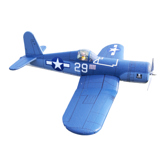
F-4U Corsair
Electric powered RC model kit
850 mm
740 mm
350-450 g
3 pcs
1 piece
5 pcs
2 pcs
1 piece
1 piece
3 pcs
1 + 2 pcs
1 + 1 piece
1 piece
gear
-
MPJ 5:1
-
-
MPJ 5:1
regulator
TMM 1210-3
TMM 1210-3
TMM 1210-3
TMM 1210-3
TMM 0810
propeller
APC 9x6
APC 9x6
APC 9x6
APC 9x6
APC 9x6
Advertisement
Table of Contents

Related Manuals for LM model F-4U Corsair

Summary of Contents for LM model F-4U Corsair
- Page 1 F-4U Corsair Electric powered RC model kit Wingspan: 850 mm Length: 740 mm Také off weight: 350-450 g The kit of this model is mostly maid of extruded polypropylen (EPP). This material ensures extreme robustness and durability. Thanks to its handling and manoeuvreing abilities, it is capable of relaxing flight as well as of more complicated aerobatic manoevres, eventualy air combat.
- Page 2 Now, glue the completed wing to the slot in the fuselage. Work carefully, using polyurethane glue. In the center part of horizontal stabilizer, cut a slot for carbon stripe. Glue it by cyanoacrylate glue in here. Now, make up the elevator joint, using iron wire. Glue it in. Now, glue the Horizontal and vertical stabilizers to the fuselage.
- Page 3 1) Cut the servo compartment 2) Insert the aileron servo 3) Make cut for wing plywood joint 4) Glue the plywood wing joints to the center part 5) Glue center and inner wing sections together 6) Make a cut for carbon stripe using sharp knife...
- Page 4 7) Insert and glue carbon stripe 8) Glue the wing sections together 9) Cut the removeable cover, lower fuselage part 10) Glue the cross-cutted lower fuselage part Make the cut for bowden, rear fuselage part 12) Glue both fuselage sections together...
- Page 5 13) Glue parts of engine cowling 14) Drill engine mounting holes and glue the engine bulkhead 15) Try the engine placing before glueing 16) Glue whole unit to the front fuselage section 17) Make a cut ang glue the carbon stripe 18) Join the elevator using U-shaped iron wire.
- Page 6 19) Plue the wing into the fuselage 20) Glue the empennage 21) Push rods made up from iron wire 22) After the paint, glue the cabin 23) Place the RC equipement as necessary to get the C.G. position. Place the accumulator as far in the front as possible...
- Page 7 Detachable wing variation Cut the lower fuselage part Glue the cutted part to the lower wing surface Glue the front plywood part Glue the rear plywood part for plastic female screw placement Make a shallow cut in the rear part and glue the plywood reinforcement Drill a hole and glue the stick...
- Page 8 Finaly, check the centre of gravity position. In case of using the haevier power unit, put necessary balance in the rear part. For beginning, set the control surfaces angle to app. 30°. Choose calm wind weather for first flights. Always fly in safe manner, so that no one including yourself could not get hurt or endangered!! Many happy moments with your new model! Libor Mašík Kobeřice...
Need help?
Do you have a question about the F-4U Corsair and is the answer not in the manual?
Questions and answers