Table of Contents
Advertisement
Instruction Manual
Form 2007
October 1996
Type 304 and 304L Electrical
Position Switch
Contents
. . . . . . . . . . . . . . . . . . . . . . . . . . . . . . .
. . . . . . . . . . . . . . . . . . . . . . . . . . . .
. . . . . . . . . . . . . . . . . . . . . . . . . . . . . . . . .
. . . . . . . . . . . . . . . . . . . . . . . . . . . . . .
. . . . . . . . . . . . . . . . . . . . . . . . . . . . . . . .
. . . . . . . . . . . . . . . . . . . . . . . . . . . . . .
. . . . . . . . . . . . . . . . . . . . . . . . . . . . . . .
. . . . . . . . . . . . . . . . . . . . . . . . . . . . . .
. . . . . . . . . . . . . . . . . . . . . . . . . . . .
. . . . . . . . . . . . . . . . . . . . . . . . . . . . . . . . .
Introduction
Scope of Manual
This instruction manual provides installation, adjust-
ment, maintenance, and parts ordering information for
the Type 304 and 304L electrical position switches.
This manual also provides ordering information for the
hardware used to mount the switches on Fisher actua-
tors.
Fisher, Fisher-Rosemount, and Managing The Process Better are marks owned
by Fisher Controls International, Inc. or Fisher-Rosemount Systems, Inc.
All other marks are the property of their respective owners.
Fisher Controls International, Inc. 1987, 1996; All Rights Reserved
. . .
. . . . . . . . . . . . . . . . . . . . . . .
. . . . . . . . . . . . . . . . . . .
. . . . . . . . . . . . . . .
. . . . . . . . . . . . . . . . . . . . .
. . . . . . . . . . . . . . .
. .
22
Type 304 & 304L
1
1
1
1
3
3
4
W5939 / IL
5
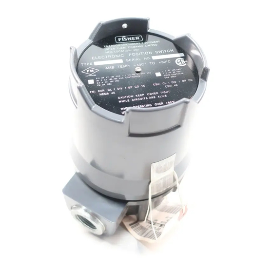
Figure 1. Type 304 Electrical Position Switch with
6
Cover Removed
6
Only personnel qualified through training or experience
should install, operate, and maintain these position
7
switches. If you have any questions concerning these
instructions, contact your Fisher Controls sales office
8
or sales representative before proceeding.
8
Description
8
The Type 304 and 304L switches are normally
8
mounted on a control valve actuator to operate
8
alarms, signal lights, relays, solenoid valves, or other
equipment when valve travel reaches predetermined
points.
The Type 304 position switch (see figure 1) is for ap-
plications that require only one or two switches. The
Type 304L position switch is for applications that re-
quire three or more switches with a maximum of six
switches (see figure 3). The individual switches can be
adjusted to operate at any point of travel within the 90
degrees of cam rod rotation.
Specifications
Specifications for the Type 304 and 304L electrical
position switches are listed in table 1.
Advertisement
Table of Contents

Related Manuals for Fisher 304


Summary of Contents for Fisher 304
-
Page 1: Table Of Contents
Additional Actuator Parts for Field Mounting equipment when valve travel reaches predetermined points. The Type 304 position switch (see figure 1) is for ap- plications that require only one or two switches. The Introduction Type 304L position switch is for applications that re- quire three or more switches with a maximum of six switches (see figure 3). - Page 2 Service Ratings (when wired at the factory): See tables 2 and 3 Approximate Weight Maximum Continuous Current: 20 amperes Type 304 (with 2 switches and cover): 5 pounds (2.3 kg) Maximum Inrush Current: 30 amperes with normal- Type 304L (with 6 switches and long cover): 10 ly-closed contacts;...
-
Page 3: Installation
225, 450, and 675 Additional field mounting parts – – – 1. Contact your Fisher Controls sales office or sales representative for information for mounting on actuator types and sizes not listed. WARNING Avoid personal injury from sudden re- lease of process pressure. Before disas-... -
Page 4: Mounting The Position Switch On Other Devices
Type 304 & 304L GROUND TERMINAL CAM EAR GEARED ROLLER ROLLER ADJUSTMENT SWITCH BASE W5940 / IL Figure 3. Location of Parts for T ype 304L Position Switch tion must be with an approved meter for operating information sections to place the position switch in operation. -
Page 5: Electrical Connections
Type 304 & 304L Maximum Intermediate Maximum Clockwise Shaft Position Counterclockwise Shaft Rotation Shaft Rotation MARKED COM MARKED NC NO COM NO COM NO COM Switch Set to change State at maximum counter- clockwise shaft rotation MARKED NO TYPICAL SWITCH HOUSING... -
Page 6: Adjustment
Type 304 & 304L OPTIONAL SWITCHES SWITCH 1 ACTUATES AT VALVE ACTUATOR STEM ARE SET AS REQUIRED CLOSED POSITION CAM ROD ROLLER ADJUSTMENT SCREW SMALL RADIUS CAM HEEL GEARED NUT 1/16 INCH CAM EAR (1.6 mm) 3/8–INCH (9.5 mm) RADIUS... -
Page 7: Maintenance
WARNING as calibration) or replace components in an instrument that carries a third-party approval. When you replace compo- For 304 switches in intrinsically safe nents, use only components specified areas, current monitoring during must by the factory. Substitution with other... -
Page 8: Parts Ordering
Type 304 & 304L Description Part Number Parts Ordering Terminal Strip Assembly (figure 6) Whenever corresponding with the Fisher sales office Screw, pl steel or sales representative about this equipment, always 2 switch unit mention the position switch serial number. When or- 1 switch (4 req’d) - Page 9 Type 304 & 304L APPLY LUB/ADHESIVE NOTES: WIRE ASSEMBLIES REQUIRED ON SWITCHES WITH TERMINAL STRIP ONLY RED WIRE ASSEMBLY (KEY 35) CONNECTS SWITCH NORMALLY CLOSED (NC) CONNECTION TO NC ON TERMINAL STRIP BLUE WIRE ASSEMBLY (KEY 36) CONNECTS SWITCH COMMON (C) CONNECTION TO C ON TERMINAL STRIP BLACK WIRE ASSEMBLY (KEY 37) CONNECTS SWITCH NORMALLY OPEN (NO) CONNECTION TO NO ON TERMINAL STRIP 30A8003–L / IL...
- Page 10 REFER TO THE PARTS LIST FOR KEY NUMBERS DESCRIPTION AND ORDERING INFORMATION. REFER TO THE ADDITION PARTS FOR FIELD MOUNTING SECTION FOR ACTUA TOR PARTS REQUIRED FOR MOUNTING THE TYPE 304 AND 304L SWITCHES. 42A2088–D / IL Figure 7. Typical Switch Mounting for 350 Series Actuators; T ype 470 and 478 Actuators, Size 40 through 68; and T ype 657 and 667...
- Page 11 REFER TO THE PARTS LIST FOR KEY NUMBER DESCRIPTION AND ORDERING INFORMATION. REFER TO THE ADDITIONAL PARTS FOR FIELD MOUNTING SECTION FOR ACTUA TOR PARTS REQUIRED FOR MOUNTING THE TYPE 304 AND 304L SWITCHES. 30A7539–E / IL Figure 8. Typical Switch Mounting for T ype 470 Actuator, Size 30 and Type 470 Actuator , Size 80 with Covered Y oke...
- Page 12 REFER TO THE PARTS LIST FOR KEY NUMBER DESCRIPTION AND MOUNTING SECTION FOR ACTUATOR PARTS REQUIRED FOR MOUNTING ORDERING INFORMATION. REFER TO THE ADDITIONAL PARTS FOR FIELD THE TYPE 304 AND 304L SWITCHES. MOUNTING SECTION FOR ACTUATOR PARTS REQUIRED FOR MOUNTING 32A2267–B / IL THE TYPE 304 AND 304L SWITCHES.
- Page 13 Type 304 & 304L HOLE 2 ACTUATOR STEM HOLE 1 37A9020–B B1819–1 / IL TRAVEL HOLE Inches 29.6 or less 1–1/8 or less 38.1 to 50.4 1–1/2 to 2 63.5 to 229 2–1/2 to 3 88.9 to 102 3–1/2 to 4...
- Page 14 ORDERING INFORMATION. REFER TO THE ADDITIONAL PARTS FOR FIELD MOUNTING SECTION FOR ACTUATOR PARTS REQUIRED FOR MOUNTING Sizes 40MO and 45MO 2N253628992 THE TYPE 304 AND 304L SWITCHES. Sizes 50 and 60 w/covered yoke 2N253728992 30A7540–F Size 70 w/covered yoke 3N879925022 Figure 13.
- Page 15 MOUNTING SECTION FOR ACTUATOR PARTS REQUIRED FOR MOUNTING Sizes 40, 45, 46, 50, and 60 1U9987000A2 THE TYPE 304 AND 304L SWITCHES. Sizes 40, 45, 46, 50, and 60 w/covered yoke 1U9987000A2 STEM CONNECTION FOR LESS THAN 8–1/8 INCHES (207 mm) TRAVEL...
- Page 16 ORDERING INFORMATION. REFER TO THE ADDITIONAL PARTS FOR FIELD MOUNTING SECTION FOR ACTUATOR PARTS REQUIRED FOR MOUNTING THE TYPE 304 AND 304L SWITCHES. 42A1841–C / IL Figure 15. T ypical Switch Mounting for All Sizes of T ype 657 and 667 Actuators with...
- Page 17 Type 304 & 304L Description Part Number Description Part Number Cap screw, pl steel (cont) Hex Nut, pl steel (2 req’d) (2 req’d) Sizes 40, 45, 46, 50, 60, and 70 1A342124122 Sizes 40, 45, 46, 50, 60, 70, and 70MO...
- Page 18 ORDERING INFORMATION. REFER TO THE ADDITIONAL PARTS FOR FIELD MOUNTING SECTION FOR ACTUATOR PARTS REQUIRED FOR MOUNTING THE TYPE 304 AND 304L SWITCHES. 52A9379–F / IL Figure 16. T ypical Switch Mounting for T ype 1051, 1052, and 1061 Actuators, Sizes 30, 40, 60, 68, and 70...
- Page 19 REFER TO THE PARTS LIST FOR KEY NUMBER DESCRIPTION AND ORDERING INFORMATION. REFER TO THE ADDITIONAL PARTS FOR FIELD MOUNTING SECTION FOR ACTUATOR PARTS REQUIRED FOR MOUNTING THE TYPE 304 AND 304L SWITCHES. 39A2422–A A3203–1 / IL Figure 19. T ypical Switch Mounting for T ype 1052...
- Page 20 REFER TO THE PARTS LIST FOR KEY NUMBER DESCRIPTION AND ORDERING INFORMATION. REFER TO THE ADDITIONAL PARTS FOR FIELD MOUNTING SECTION FOR ACTUATOR PARTS REQUIRED FOR MOUNTING THE TYPE 304 AND 304L SWITCHES. Figure 21. T ypical Switch Mounting for T ype 1076 Actuator...
- Page 21 Type 304 & 304L 30B0652–A / IL NOTE: REFER TO THE PARTS LIST FOR KEY NUMBER DESCRIPTION AND ORDERING INFORMATION. 40B0653–A / IL Figure 22. T ypical Switch Mounting for T ype 1077 Actuator Description Part Number Description Part Number...
-
Page 22: Additional Actuator Parts For Field Mounting
REFER TO THE PARTS LIST FOR KEY NUMBER DESCRIPTION AND ORDERING INFORMATION. REFER TO THE ADDITIONAL PARTS FOR FIELD MOUNTING SECTION FOR ACTUATOR PARTS REQUIRED FOR MOUNTING THE TYPE 304 AND 304L SWITCHES. 31B6967–A / IL Figure 23. T ypical Switch Mounting for T ype 1078 Actuator... - Page 23 Type 304 & 304L NOTE: REFER TO THE PARTS LIST FOR KEY NUMBER DESCRIPTION AND ORDERING INFORMATION. 40B7395–A / IL Figure 24. T ypical Switch Mounting for T ype 1250 and 1250R Actuators Description Part Number - - - Washer, steel (figure 24) Type 513, 513R/32 (2 req’d)
- Page 24 Type 304 & 304L Description Part Number Description Part Number - - - Travel Indicator, stainless steel (not shown) - - - Travel Indicator Scale, stainless steel (not shown) 1 in. (25.4mm) stem 1051/33; 1052/33 20B1542X012 470/80, 80 w/covered yoke, 86, 100;...
Need help?
Do you have a question about the 304 and is the answer not in the manual?
Questions and answers