Table of Contents
Advertisement
Instruction Manual
D200119X012
Fisher
2100 Pneumatic and 2100E Electric
™
Liquid Level Switches
Contents
. . . . . . . . . . . . . . . . . . . . . . . . . . . . . . . . .
. . . . . . . . . . . . . . . . . . . . . . . . . . . . .
. . . . . . . . . . . . . . . . . . . . . . . . . . . . . . . . .
. . . . . . . . . . . . . . . . . . . . . . . . . . . . . . .
. . . . . . . . . . . . . . . . . . . . . . . . . . . . . . . . . .
. . . . . . . . . . . . . . . . . . . . . . . . . . . .
. . . . . . . . . . . . . . . . . . . . . . . . . . . . . . . .
. . . . . . . . . . . . . . . . . . . . . . . . . . . .
. . . . . . . . . . . . . . . . . . . . . . . . . . . . . . .
. . . . . . . . . . . . . . . . . . . . . . . . . . . . . . . . . . .
. . . . . . . . . . . . . . . . . . . . . . . . . . . . . . . . . . .
Introduction
Scope of Manual
This instruction manual includes installation, maintenance, and parts information for the 2100 pneumatic and 2100E
electric liquid level switches. Refer to separate instruction manuals when you require information regarding related
valves, actuators, positioners, and accessories.
Do not install, operate or maintain a 2100 pneumatic or a 2100E electric liquid level switch without being fully trained
and qualified in valve, actuator and accessory installation, operation and maintenance. To avoid personal injury or
property damage it is important to carefully read, understand, and follow all of the contents of this manual, including
all safety cautions and warnings. If you have any questions about these instructions, contact your
or Local Business Partner before proceeding.
www.Fisher.com
. . . . . . . . . . . . . . . . . . . . . . . . .
. . . . . . . . . . . . . . . . . . .
. . . . . . . . . . . . . . . . . . . . . . .
. . . . . . .
. . . . . .
. . . . . . . . . . . . . . . . . . . . . . . . .
. . . . . . . . . .
. . . . . . . . .
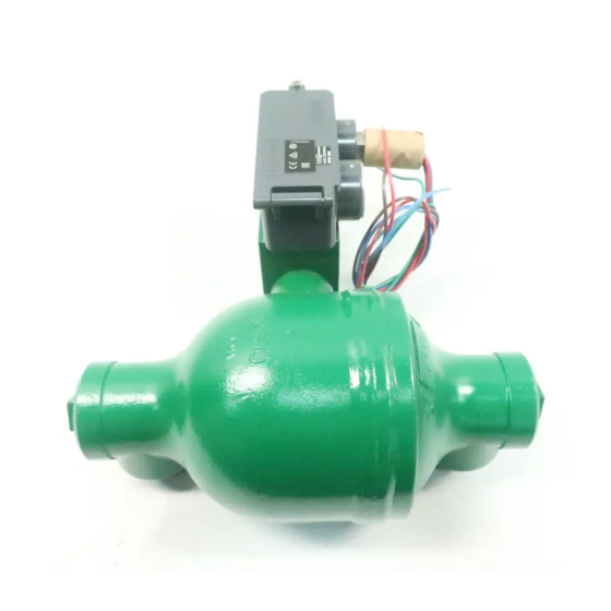
Figure 1. Fisher 2100 Pneumatic Liquid Level Switch
1
1
2
2
4
4
4
6
6
6
. . . . .
7
8
9
10
10
12
13
14
14
15
2100 and 2100E Liquid Level Switches
APPROXIMATE
SWITCHING POINT
Emerson sales office
June 2017
Advertisement
Table of Contents

Subscribe to Our Youtube Channel
Related Manuals for Fisher 2100


Summary of Contents for Fisher 2100
-
Page 1: Table Of Contents
Do not install, operate or maintain a 2100 pneumatic or a 2100E electric liquid level switch without being fully trained and qualified in valve, actuator and accessory installation, operation and maintenance. To avoid personal injury or property damage it is important to carefully read, understand, and follow all of the contents of this manual, including all safety cautions and warnings. -
Page 2: Description
D200119X012 Description The on‐off 2100 pneumatic switch (figure 1) and the 2100E electric switch (figure 2) operate shutdown valves or alarm systems when liquid in a vessel reaches a predetermined level. The 2100 switch uses an externally mounted displacer that operates a nozzle‐flapper to vent the supply pressure when the switch is activated. The nozzle‐flapper has a soft seat for tight shutoff when the switch is in its normal position (flapper against the nozzle). - Page 3 The 2100 pneumatic switch complies with the requirements of ATEX Group II Category 2 Gas and 2100 Switch: J 2.1 to 4.1 bar (30 to 60 psig), J 4.1 Dust to 6.9 bar (60 to 100 psig), or J 6.9 to 10.3 bar (100...
-
Page 4: Educational Services
2100 and 2100E Liquid Level Switches June 2017 D200119X012 Educational Services For information on available courses for 2100 pneumatic and 2100E electric liquid level switches, as well as a variety of other products, contact: Emerson Automation Solutions Educational Services - Registration Phone: 1-641-754-3771 or 1-800-338-8158 E-mail: education@emerson.com... - Page 5 Instruction Manual 2100 and 2100E Liquid Level Switches D200119X012 June 2017 ATEX— II 2 G D IECEx— Ex d IIC T4/T5/T6 Gb ; Ex tb IIIC Txx_C Db Model 057-0770: Gas Ex d IIC T6 (Ta = -40_C to +70_C) (5 A Max) ; Ex d IIC T5 (Ta = -40_C to +75_C) (11 A Max) Dust Ex tb IIIC T85_C Db IP6X (Ta = -40_C to +70_C) (5 A Max) ;...
-
Page 6: Installation Procedures
The horizontal line forged on the displacer cage indicates the approximate switching point (figures 1 and 2). When you mount the 2100 or 2100E switch, position it so that the horizontal line corresponds to the horizontal level at which switching is desired. -
Page 7: Additional Procedures For 2100E Switch
To change switch action from low‐level to high‐level switching or vice versa, reverse the positions of the nozzle, flapper, and magnet according to steps 1 through 7 and 10 through 18 of the 2100 switch maintenance procedure. To change switch mounting from right‐hand to left‐hand or vice versa, perform steps 1 through 7 and 9 through 18 of the 2100 switch maintenance procedure. -
Page 8: Calibration Check
To reverse action of the 2100E switch, refer to table 2 and reinstall wiring for normally open (NO) switches to normally closed (NC) and vice versa. To change switch mounting from right‐hand to left‐hand or vice versa, perform steps found in the 2100 switch maintenance procedure. -
Page 9: Principle Of Operation
Principle of Operation The 2100 switch (figure 4) is an external, cage‐mounted, pneumatic liquid level switch. When the switch is in the normal position with the flapper against the nozzle, output pressure cannot bleed off and remains the same as full supply pressure. -
Page 10: Maintenance
Inspect the vent or vent screen (key 23) or vent line periodically to ensure that the vent or vent line is not plugged. Table 3 lists various 2100 switch problems and possible solutions for them. The table is valid for either high‐level or low‐level switching action and for any supply pressure range. - Page 11 This test should be conducted with no process fluid in the cage using the following procedures: 1. Make sure the 2100 switch flapper and clamp assembly (key 12, figure 5) or the 2100E switch arm (key 40, figure 6) is tight on the shaft of the torque tube assembly (key 7).
-
Page 12: 2100 Switch Maintenance Procedure
Instruction Manual 2100 and 2100E Liquid Level Switches June 2017 D200119X012 2100 Switch Maintenance Procedure WARNING When disconnecting any of the pneumatic connections, natural gas, if used as the supply medium, will seep from the unit and any connected equipment into the surrounding atmosphere. Personal injury or property damage may result from fire or explosion if preventative measures are not taken, such as adequate ventilation and the removal of any ignition sources. -
Page 13: 2100E Switch Maintenance Procedure
Instruction Manual 2100 and 2100E Liquid Level Switches D200119X012 June 2017 13. Install the pipe plug (key 2), or the bushing and sight window assembly (keys 4 and 5), into the body block (key 3). Torque the pipe plug, or the bushing and sight window assembly, to between 68 and 136 NSm (50 and 100 lbfSft). -
Page 14: Parts Ordering
Use only genuine Fisher replacement parts. Components that are not supplied by Emerson Automation Solutions should not, under any circumstances be used in any Fisher instrument. The use of components not manufactured by Emerson Automation Solutions may void your warranty, might adversely affect the performance of the instrument, and could result in personal injury and property damage. -
Page 15: Parts List
Instruction Manual 2100 and 2100E Liquid Level Switches D200119X012 June 2017 Parts List Description Flapper Seat, fluorocarbon Flapper and Clamp Assembly, stainless steel Magnet Bracket, stainless steel Note Magnet, sintered Alnico Cover, plastic Contact your Emerson sales office or your Local Business Partner for Part Cover Gasket, chloroprene Ordering information. - Page 16 Instruction Manual 2100 and 2100E Liquid Level Switches D200119X012 June 2017 Figure 5. Fisher 2100 Switch Assembly Drawing SECTION C‐C DETAIL OF RIGHT HAND MOUNTING WITH NOZZLE AND FLAPPER POSITIONED FOR LOW LEVEL SWITCHING (ALSO TYPICAL OF HIGH LEVEL SWITCHING...
-
Page 17: D200119X012 June
Instruction Manual 2100 and 2100E Liquid Level Switches D200119X012 June 2017 Figure 6. Fisher 2100E Switch Assembly Drawing SECTION A‐A VIEW B OPTIONAL SIGHT WINDOW 40B6593‐G... - Page 18 Instruction Manual 2100 and 2100E Liquid Level Switches D200119X012 June 2017 Description Description Electric Switch Assembly, stainless steel O‐Ring, fluorocarbon Single pole double throw (SPDT) Cap Screw, stainless steel (2 req'd) Double pole double throw (DPDT) Machine Screw, stainless steel Plug, anodized aluminum Bearing, glass‐filled PTFE...
- Page 19 Instruction Manual 2100 and 2100E Liquid Level Switches D200119X012 June 2017...
- Page 20 Responsibility for proper selection, use, and maintenance of any product remains solely with the purchaser and end user. Fisher is a mark owned by one of the companies in the Emerson Automation Solutions business unit of Emerson Electric Co. Emerson Automation Solutions, Emerson, and the Emerson logo are trademarks and service marks of Emerson Electric Co.
Need help?
Do you have a question about the 2100 and is the answer not in the manual?
Questions and answers