Table of Contents
Advertisement
Quick Links
Download this manual
See also:
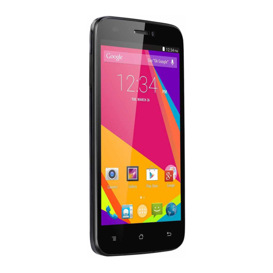
User Manual
Advertisement
Table of Contents
Troubleshooting

Related Manuals for Blu STUDIO 5.0 HD


Summary of Contents for Blu STUDIO 5.0 HD
- Page 1 BLU STUDIO 5.0 HD Service Manual 1 / 43...
-
Page 2: Trouble Shooting Guide
CAUTIONS Please refer to the phone’s user’s guide for instructions relating to operation, care, and maintenance, which include important safety information. Servicing and alignment must be undertaken by qualified personnel only. Ensure all work is carried out at an anti-static workstation and that an anti-static wrist strap is worn. Use only approved components as specified in the parts list. -
Page 3: Chapter 1 Introduction
CHAPTER 1 INTRODUCTION S5501 Main Function Full Touch Smartphone Android 4.2 CPU MT 6582 1.3G Quad core 5“HD 1280*720 Camera: 8 AF Mega , Front camera: 2 Mega BT 4.0 , WIFI : 802.11b, 802.11g, 802.11n Flash Memory:8GB+1GB Dual SIM SPEC:... -
Page 4: Chapter 2 Service Tools
CHAPTER 2 SERVICE TOOLS Iron Hot air gun Voltage regulator Multimeter Solder wire, soldering paste Tweezers Driver upDownlo Wrist groun ding Pick Antistatic Computer and software download cable Metal tweezers, Screw driver etc 4 / 43... -
Page 5: Chapter 3 Disassembly And Assembly
CHAPTER 3 DISASSEMBLY AND ASSEMBLY DISASSEMBLY Remove the battery cover……... 1 Unfasten the 10 screws………………… Prize up the back cover…….………..………..3 Remove the TP connector……….4 ………4 Take out the camera…………...………..5 Remove the FPC connector………..…...………….……... 6 5 / 43... - Page 6 Unfasten the screws..…………...……7 Remove the FR coaxial line connector……...……..8 Remove the antenna PCBA……………..……….9 Remove the FPC connector………10 Remove the speaker……………..12 Remove the LED FPC……...…11 6 / 43...
- Page 7 Remove the speaker PCBA…………………..13 Remove the vibrator…………………..14 Use haet gun to heat aound the TP 200°C……..15 Remove the TP………..16 stick the protection film onto LCD…………..17 Stick the protection film onto TP……..18 7 / 43...
- Page 8 Remove the LCD…………..19 Finished。 。 。 。 。 。 。 8 / 43...
- Page 9 ASSEMBLY Remove the protection film………….2 Install the LCD……….…..………..…1 Install the TP………………………..4 Remove the protection film……….3 Solder the LED FPC…………..6 Install the speaker PCBA…….………..5 9 / 43...
- Page 10 Install the FPC………………7 Install the vibrator…………..8 Install the antenna PCBA……..…………9 Install the RF coaxial line……………………….…10 Fasten the screws………….…..…12 Install the PCBA…..…………………11 10 / 43...
- Page 11 Install the TP connector…..……13 Install the camera……..……14 Install the FPC connector..……15 Install the RF coaxial line.……16 Finished……… Install the speaker ……..……17 Solder the back cover…..……18 11 / 43...
- Page 12 Fasten the 10 screws………...……19 Install the battery cover……………..…20 Finished 12 / 43...
- Page 13 CHAPTER 4 SYSTEM BLOCK DIAGRAM 5.1 PCBA A-Side U701 BT/WIFI/FM/GPS IC. J1003 Earphone connector. J1203 I/O connector. bug Buy by damaged. bug by damaged. by damaged. BT/WIFI/FM/GPS Not work Earphone no sound No charge. Can’t software. U101 CPU Bug by damaged Cannot power on.
- Page 14 PCBA B-Side J901 Camera connector U901 Flashlight driver IC Bug by damaged. Bug by damaged. Can’t take photos. Flashlight don’t light. J802 TP Connector J903 Camera connector Bug by damaged. Bug by damaged. TP not work. Can’t take photos. J1201 T-Flash Connector J801 LCD Connector Bug by damaged Bug by damaged.
- Page 15 Side A layout Side B layout 15 / 43...
- Page 16 CHAPTER 5 UNIT CIRCUIT PRINCIPLE INTRODUCTION 5.1 MT6582 INTRODUCTION System Overview Media Tek MT6582 is a highly integrated 3G System-on-chip(SoC) which incorporates advanced features e.g. HSPA R8 modem, Quad-core ARM Cortex-A7 MPCore operating at 1.2 GHz, 3D graphics (Open GLJES 2.O),8M camera ISP , LPDDR2/3 533 MHz and high-Definition 1080p video decoder. MT6582 helps phone manufacturers build high-performance 3G smart phones with PC-like browser, 3D gaming and cinema class home entertainment experiences.
- Page 17 5.2 Baseband CPU circuit introduction for power supply power supply part 17 / 43...
- Page 18 5.3 Introduction for baseband chip CPU signal output part circuit 18 / 43...
- Page 19 Four in one MT6627 MT6627 is a 4-in-1 wireless communication device which includes . WLAN . Bluetooth . GPS . FM Transmitter and receiver With four advanced radio technologies integrated into a single chip, MT6627 provides the best and most convenient Connectivity functions.
-
Page 20: General Descriptions
Power management IC MT6323 General Descriptions MT6323 is a fully integrated PMIC target for smart phone power provider. See Figure 3-1 the block diagram for the whole picture of MT6323 PMIC 20 / 43... - Page 21 5.6 WCDMA PA IC Description The SKY7776XX Power Amplifier Module (PAM) is a fully matched 10-pad surface mount module developed for Wideband Code Division Multiple Access (WCDMA) applications, This small and efficient module packs full 1920-1980 MHz bandwidth coverage into a single compact package. Because of high efficiencies stained throughout the entire power range, the SKY7776X delivers unsurpassed talk-time advantages.
- Page 22 SKY7775XX POWER AMPLIFIER MODULE FOR CDMA/WCDMA/HSDPA/HSUPA/HSPA+/LTE- DAND 22 / 43...
-
Page 23: Chapter 6 Troubleshooting
CHAPTER 6 TROUBLESHOOTING CANNOT POWER ON-CURRENT SWING INSTABILITY Cannot power on Upgrade the software Check the power manage supply output: Replace or VIO 18 Check and re-weld DVDD 2.8V replace the I/O power VIO 28 connector manage IC VTCXO 2.8V VEMC 3.3V VRTC 1.2V 26MHZ&32.768KHZ... - Page 24 MT6323 power manage supply output: 24 / 43...
- Page 25 CANNOT POWER ON-LARGE CURRENT Make the phone connect the power supply and then press power key find large current make the phone heat Check if the phone leakage (current 0mA is normal) Use the touch method to check and replace the heat spare parts Check and Check and replace...
- Page 26 REPAIR FLOW FOR PHONE DEAD Phone dead Upgrade the software can settle the defect issue? Check battery connector and battery touch point if is dropped or dirty? Clean or replace the battery or battery connector. Check the keypad if stuck or touch panel do not work to make the phone “dead”? Check and reinstall...
- Page 27 NO DISPLAY OR DISPLAY ABNORMALITY No display or display abnormality after power on Check LCD if damage or liquid flow out Change LCD Check LCD connector is OK or not Clean or re-weld the LCD connector Change LCD connector can settle the defect issue? Upgrade software Change the LCD can...
-
Page 28: Insert Sim
INSERT SIM REPAIR PROCESS Insert SIM Check if all the SIM pins are clean Clean or replace SIM connector. Check SIM connector is OK or not Clean or re-weld the SIM connector Check FPC on SIM connector is OK or not Replace FPC Replace SIM card Upgrade software... - Page 29 SIM CIRCUIT SIM1&SIM2 From power IC From power IC From power IC From power IC Power IC SIMLVS 29 / 43...
- Page 30 N0/WEAK SIGNAL TROUBLE SHOOING No or weak signal Inspect the antenna and antenna connector to see if there’s any distortion Replace the defective components. Check and replace RF coaxial line to see if there’s any signal . Replace RF coaxial line Put a false antenna at RF PA IC to see if there’s any signal Replace RF...
- Page 31 RF Circuit RF-PA Circuit 2G PA SKY77590 Antenna 2G TX 3G TX/RX 2G RX 3G TX To RF switch 3G PA SKY775XX 3G TX from RF IC power detector 31 / 43...
- Page 32 NO/LOW SOUND FROM SPEAKER No sound or noise Remove the speaker and measure with multimeter to see if there’s any sound. The phone is in Silent mode. Replace speaker. Set the phone as normal mode Check and replace FPC is ok or not. Replace FPC.
-
Page 33: Speaker Circuit
Speaker circuit Audio PA IC From power IC To speaker Audio detector 33 / 43... - Page 34 RECEIVER LOW VOICE OR NO VOICE Receiver is low. Check if the receiver is broken or damaged Replace the receiver . Check if receiver connector is Resolder or clean the receiver connector. Measure the signal with oscillograph under calling mode Resolder or replace power IC is ok or not.
-
Page 35: Receiver Circuit
Receiver circuit Main related component: BBIC(U101),power IC(U401),receiver From power IC Receiver 35 / 43... - Page 36 NO/LOW SOUND FROM MIC No/Low sound from Check if there’s MIC cover Install the MIC cover. Press power on and side button to test mode and activate echo loop, measure MIC voltage is 1.5V、0.7V Replace the MIC Replace FPC to check if the problem is solved Replace the Measure C1124、C1125...
-
Page 37: Microphone Circuit
Microphone circuit Main related component: BBIC(U101),power IC(U401),microphone To microphone From power IC 37 / 43... - Page 38 DOES NOT CHARGE – NO CHARGE IN No charge Change battery Check charger and cable without problem, or change good one Upgrade the Check if I/O connector works normal Re-solder or replace the I/O connector Check and replace FPC is ok or not? Replace the FPC Replace the charge IC is ok or not?
-
Page 39: Charge Circuit
Charge circuit Main related component: BBIC(U101),power IC(U401),charge IC(U402) I/O connector(J1203) From I/O connector To battery connector Charge IC Charge detector 39 / 43... - Page 40 CAN’T READ T-FLASH CARD Can’t read T-Flash card Check if T-Flash slot appearance was ok? Replaced the T-Flash slot Measure if T-Flash slot pin 4 VMC was 2.8V. Re-solder or replace Power IC Check if the voltage of T-Flash pin3/pin5/pin7 to the ground was around 0.7V with multimeter diode column Measure if there is pin...
- Page 41 T-Flash connector circuit Main related component: BBIC(U101),T-Flash connector(J1203) T-Flash connector From BBIC 41 / 43...
- Page 42 WIFI、BT、FM 、GPS DEFECT REPAIR FLOW CHART WIFI can’t open, Can’t work normal Software update and check the function is OK or not Software update Check 4 in 1 IC 29#.33#.36#40# pin have 1.8V, 3.3BVsupply voltage or not Check power IC have VBATT V supply voltage or Replace U701 Check U701 10pin have...
- Page 43 WIFI BT FM GPS 4 in 1 circuit Main related component: BBIC(U101),power IC(U401),4 in 1 IC(U701), antenna. WIFI&BT& control line From BBIC WIFI&BT RX/TX (From BBIC) WIFI&BT MF control line From BBIC GPS IQ RX From BBIC GPS ANT FM ANT From Earphone connector 43 / 43...
Need help?
Do you have a question about the STUDIO 5.0 HD and is the answer not in the manual?
Questions and answers