
Subscribe to Our Youtube Channel
Related Manuals for Super Star 2400


Summary of Contents for Super Star 2400
- Page 1 Operation Manual 3600 Channels 5-Mode AM/FM/USB/LSB/CW Mobile Transceiver...
-
Page 2: General Description
PLL (phase-locked-loop) circuitry. The use of PLL assures a precise on-frequency operation on every channel in both transmit and rec- eive mode. The Super Star 2400 also includes many other features which will provide greater operating convenience and assure optimum communi- cations under a wide range of conditions. -
Page 3: Specifications
Specifications General Frequency composition. PLL synthesizer Frequency range. 26.065 to 26.505 MHz 26.515 to 26.955 MHz 26.965 to 27.405 MHz 27.415 to 27.855 MHz 27.865 to 28.305 MHz 28.315 to 28.755 MHz Channels. Total 3600: 5 MODE 240(+5 KHz) 5 MODE 240(- 5 KHz) 5 MODE Frequency space. -
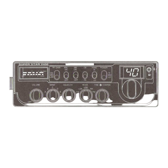
Page 4: Operating Controls And Features
Operating Controls and Features (1) Off/Volume Control Varies the sound output from the speaker. Also incorporates an on-off switch at the extremely counterclockwise position. (2) Band Selector Selects a group of 40 channels in six positions -A, B, C, D, E, or F(240 in all). (3) Squelch Control Used to eliminate any annoying background noise when no signals are present. - Page 5 (5) Fine/Coarse Control This is concentrically located control that permits individual adjustment of receiving and/or transmitting frequencies. Fine (inner knob). Provides fine tuning of the receiver section. On regular AM and FM reception, this will permit adjustment to off-frequency transmis- sions.
- Page 6 (12) NB switch Activates the noise blanker circuit which is effective in reduction of impulse type noise (ignition noise, etc.). (13) ANL switch Activates the automatic noise limiter in the audio. The ANL will be effective in reduction of atmospheric (discharge) interference. (14) RF Gain switch Selects RF Gain (receiver sensitivity) of the transceiver in 3 ways: DX.
-
Page 7: Rear Panel Connection
Rear panel Connection (1) Antenna Accepts a PL-259 type coaxial connector from the antenna lead-in cable. (2) CW Key jack Accepts a 3.5 mm 2-conductor phone plug to connect a CW key. (3) External Speaker jack Used to connect an external speaker (8 Ohm 4W) as an extra sound source. Insertion of the plug from a speaker will silence the internal speaker auto- matically. - Page 8 Mobil Installation Before installing the transceiver in a car, truck, boat, etc., Be sure to choose a location which is convenient to the operating controls, and will not inter- fere with the normal functions of the driver. The transceiver may be mounted to the underside of the instrument panel or deshboard of a car, truck, ect., By means of the special bracket that is supplied with the transceiver.
- Page 9 Channel Selection The transceiver is capable of operation on 240 channels which are divided into 6 groups of 40 channels A, B, C, D, E and F. These groups are selected with the Band Selector switch as the following. Band switch Position Frequency Range 26.065 to 26.505 MHz...
- Page 10 Fine Control 0 peation This control provides fine tuning of the receiver by 0.8 Khz. On regular AM or FM reception, this will permit slight adjustment of your tuning in ca- ses where the received signal is slightly off-frequency. For SSB reception, this control is used as a voice clarifier by turning it for clearest, most i1ntel- ligible voice.
Need help?
Do you have a question about the 2400 and is the answer not in the manual?
Questions and answers