Table of Contents
Advertisement
Quick Links
Studer Vista 5 M3
Digital Mixing System, SW V4.9
0.
Safety/Conformity Information
1.
Introduction, Operating Features
2.
Desk Operation
3.
Parameter Description
4.
Graphical Controller (GC) Operation
5.
AutoTouch+ Dynamic Automation
6.
Session Configuration Tool (Option)
7.
DAW Control
8.
RELINK - Resource Linking
9.
SCore Live
10.
Additional Information:
Meterbridge Installation
Operating Instructions
Advertisement
Chapters
Table of Contents

Related Manuals for Studer Vista 5 M3


Summary of Contents for Studer Vista 5 M3
- Page 1 Studer Vista 5 M3 Digital Mixing System, SW V4.9 Safety/Conformity Information Introduction, Operating Features Desk Operation Parameter Description Graphical Controller (GC) Operation AutoTouch+ Dynamic Automation Session Configuration Tool (Option) DAW Control RELINK - Resource Linking SCore Live Additional Information: Meterbridge Installation Operating Instructions...
- Page 2 Prepared and edited by Copyright by Studer Professional Audio GmbH Studer Professional Audio GmbH Technical Documentation Order no. 5036304 Riedthofstrasse 214 CH-8105 Regensdorf - Switzerland http://www.studer.ch Subject to change Studer is a registered trade mark of Studer Professional Audio GmbH, Regensdorf...
- Page 3 • Only use attachments/accessories specified by the manufacturer. • Use only with the cart, stand, tripod, bracket or table specified by the manufacturer, or sold with the apparatus. When a cart is used, use cau- tion when moving the cart/apparatus combination to avoid injury from tip-over. • Refer all servicing to qualified service personnel. Servicing is required when the apparatus has been damaged in any way, such as the power supply cord or plug is damaged, liquid has been spilled or objects fallen into the apparatus, the apparatus has been exposed to rain or moisture, does not operate normally, or has been dropped. Note: It is recommended that all maintenance and service on the product should be carried out by Studer or its authorised agents. Studer cannot accept any liability whatsoever for any loss or damage caused by service, maintenance or repair by unauthorised personnel. WARNING: To reduce the risk of fire or electric shock, do not expose this apparatus to rain or moisture. Do not expose the apparatus to dripping or splashing and do not place objects filled with liquids, such as vases, on the appara- tus. • No naked flame sources, such as lighted candles, should be placed on the apparatus. • Ventilation should not be impeded by covering the ventilation openings with items such as newspapers, table cloths, curtains etc. WARNING: Do not use this apparatus in very dusty atmospheres, or in atmospheres containing flammable gases or chemicals.
- Page 4 Safety Information • Protective Earth (Ground): Green/Yellow (US: Green or Green/ Yellow) • Neutral: Blue (US: White) • Live (Hot): Brown (US: Black) As the colours of the wires in the mains lead may not correspond with the coloured markings identifying the terminals in your plug, proceed as follows: • The wire which is coloured Green and Yellow must be connected to the terminal in the plug which is marked with the letter E or by the earth symbol. • The wire which is coloured Blue must be connected to the terminal in the plug which is marked with the letter N. • The wire which is coloured Brown must be connected to the terminal in the plug which is marked with the letter L. Ensure that these colour codes are followed carefully in the event of the plug being changed • This unit is capable of operating over a range of mains voltages, as marked on the rear panel.
-
Page 5: Safety Information
Safety Information Conforming to this directive will minimise the risk of hearing damage caused by long listening periods. A simple rule to follow is: The longer you listen, the lower the average volume should be. Please take care when working with your audio system –... - Page 6 Installation General Installation Instructions Please consider besides these general instructions also any product-specific instructions in the “Installation” chapter of this manual. Unpacking Check the equipment for any transport damage. If the unit is mechanically damaged, if liquids have been spilled or if objects have fallen into the unit, it must not be connected to the AC power outlet, or it must be immediately disconnected by unplugging the power cable.
- Page 7 Installation / EMC Class I Equipment (Mains Operation) Should the equipment be delivered without a matching mains cable, the latter has to be prepared by a trained person using the attached female plug (IEC 320 / C13 or IEC 320 / C19) with respect to the applicable regulations in your country.
- Page 8 EMC / Maintenance / ESD • Use a system grounding concept that satisfies the safety requirements (class I equipment must be connected with a protective ground conduc- tor) and that also takes into consideration the EMC require ments. When deciding between radial, surface, or combined grounding, the advantages and disadvantages should be carefully evaluated in each case.
- Page 9 ESD / Repair • When performing a repair by replacing complete assemblies, the removed assembly must be sent back to the supplier in the same packing material in which the replacement assembly was shipped. If this should not be the case, any claim for a possible refund will be null and void. • Unpacked ESD sensitive components should only be handled in ESD protected areas (EPA, e.g.
- Page 10 Repair / Disposal SMD Components Studer has no commercially available SMD components in stock for service purposes. For repair, the corresponding devices have to be purchased locally. The specifications of special components can be found in the service manual. SMD components should only be replaced by skilled specialists using appro- priate tools.
- Page 11 Any changes or modifications not expressly approved by the manufacturer could void the user’s authority to operate the equipment. Also refer to relevant information in this manual. CE Declaration of Conformity Studer Professional Audio GmbH, CH-8105 Regensdorf, declare under our sole responsibility that the product Studer Vista 5, Vista 5 SR, Vista 5 M2 and Vista 5 M3, Digital Mixing Systems (from serial no. 1000),...
- Page 12 Under these conditions the unit or system starts and works without any prob- lem. Beyond these specifications, possible problems are described below. Ambient Temperature Units and systems by Studer are generally designed for an ambient tempera- ture range (i.e. temperature of the incoming air) of +5 °C to +40 °C. When rack mounting the units, the intended air flow and herewith adequate cooling must be provided. The following facts must be considered: • The admissible ambient temperature range for operation of the semicon-...
- Page 13 Appendix evaporation (sublimation) may be expected; otherwise the system must be heated and dried while switched off. A system without visible internal formation of ice or condensation should be heated up with its own heat dissipation, as homogeneously (and subsequently as slow) as possible;...
- Page 14 Appendix Appendix 2: Mains Connector Strain Relief For anchoring connectors without a mechanical lock (e.g. IEC mains connec- tors), we recommend the following arrangement: Procedure: The cable clamp shipped with your unit is auto-adhesive. For mounting please follow the rules below: • The surface to be adhered to must be clean, dry, and free from grease, oil, or other contaminants.
- Page 15 The following Terms and Conditions grant the right to use all programs of Studer that are part of the System and/or its options at the time of its delivery to the Customer, as well as the installation software on the original data disk and the accompanying documentation (‘License Material’).
- Page 16 Reverse engineering is only permitted with the express consent of Studer. The consent of Studer can be obtained but is not limited to the case in which the interface software can not be provided by Studer. In any case Studer has to be informed immediately upon complete or partial reverse engineering.
-
Page 17: Table Of Contents
Vista 5 M3 Digital Mixing System CHAPTER 1 Introduction ...............................3 Operating Principles ............................3 ...............................4 1.1.1 Vistonics ® .......................7 1.1.2 Momentary/Latching Key Activation 1.1.3 Ganging ................................. 8 1.1.4 Copy/Paste................................9 1.1.5 Scrolling ................................10 ..............................11 1.1.6 FaderGlow ™ 1.1.7 TFT Level Meters (Option) ..........................12 The Graphical Controller (GC) .........................13... - Page 18 Vista 5 M3 Digital Mixing System 1-2 Introduction SW V4.9 Document generated: 28.08.13...
-
Page 19: Introduction
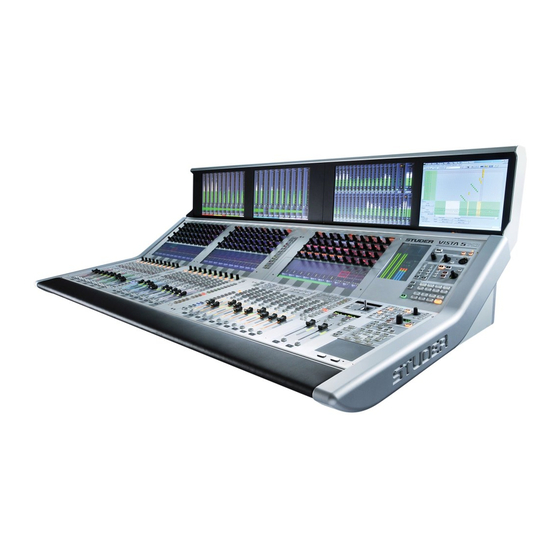
Vista 5 M3 Digital Mixing System INTRODUCTION Operating Principles Studer Vista 5 M3 incorporates operating principles that are applicable throughout nearly the whole console operation: • Vistonics ® • Momentary/Latching Key Activation • Ganging • Scrolling • FaderGlow ® • TFT Meterbridge (optional, see picture above) These operating principles are described below. They are freely combinable. -
Page 20: Vistonics
Vista 5 M3 Digital Mixing System 1.1.1 Vistonics ® Vistonics allows color and shape of controls to be varied according to good ® ergonomic practice. A given audio function is always associated with the same color, and a parameter is always associated with the same icon displaying values graphically –... - Page 21 Vista 5 M3 Digital Mixing System Global Views Up to four different parameters are shown in each channel strip. The same four parameters will be shown globally on the whole console. This mode is meant to be the ‘horizontal way of operation’, mostly used for e.g. operating auxiliaries or input settings.
- Page 22 Vista 5 M3 Digital Mixing System Local Views By touching the graphics shown below the Vistonics rotary controls, the ® whole parameter set of that specific curve is displayed, also covering some of the neighboring channel strips. It is also possible to touch any two curves in one bay in order to display both at the same time.
-
Page 23: Momentary/Latching Key Activation
Momentary/Latching Key Activation A lot of key presses during console operation are repetitive in order to compare settings or to make quick checks for monitoring purposes. The Studer Vista consoles have reduced the amount of required key presses tremendously by... -
Page 24: Ganging
On top of grouping certain channels together in a way commonly known as VCA groups, Studer Vista has the ability to link multiple channels temporar- ily together and let them behave like one single channel. Such a link is called a Gang. -
Page 25: Copy/Paste
Vista 5 M3 Digital Mixing System 1.1.4 Copy/Paste Copying certain audio settings across the console is made very fast and easy: There is a set of global channel processing keys in the center of the desk. • Select the source channel. • Set the desired processing parameters. -
Page 26: Scrolling
‘sweet spot’ at all times. This concept can also be imagined like moving a chair in front of an analog console. On Studer Vista, you move the surface of an imaginary console six times larger than the physical console. -
Page 27: Faderglow
Vista 5 M3 Digital Mixing System Step 2 The user can now navigate through the ‘virtual surface’ (6 sections wide) in two ways: Either he jumps to a specific section by pressing the corresponding key in the control bay, or he scrolls from the present position to the destination by pressing one of the arrow keys (<... -
Page 28: Tft Level Meters (Option)
Vista 5 M3 Digital Mixing System 1.1.7 TFT Level Meters (Option) As an option, additional TFT screens may be fitted to the top of the desk to provide a full mono, stereo or surround meter for every fader on the desk. -
Page 29: The Graphical Controller (Gc)
Vista 5 M3 Digital Mixing System whatever is desired via the strip set-up. There are four configurable user page pages, one with ten slots in one row, one with 20 slots in two rows, and two with 40 half-width slots in two rows. So if calling up page four, there are 40 meters, and they can be virtually anything. -
Page 30: Gc Screen Examples
Vista 5 M3 Digital Mixing System 1.2.1 GC Screen Examples Internal Routing Matrix Control The Channel Patch screen is an audio path-oriented view for controlling the routing of a particular channel, and is used to set up the sequence of channel processing blocks (EQ, Insert, Delay, etc.) and metering locations within the... - Page 31 Vista 5 M3 Digital Mixing System Within the General Patch window, the various cross point routing of sources and targets (destinations) is displayed. For example, it will show which audio signals (AES/EBU in, Direct outs, etc.) connected to the DSP sections are assigned to the corresponding channels and outputs (Input channel, MADI out etc.).
- Page 32 Vista 5 M3 Digital Mixing System Snapshot Functions Display and control of snapshot settings (in other words, complete ‘pictures’ of the operating desk’s controls and of the console’s internal settings) and factory/user presets provide basic working templates. Control of snapshot/preset filters and channel protection is achieved via...
-
Page 33: Channels, Routing, And Buses
Vista 5 M3 Digital Mixing System Channels, Routing, and Buses Processing blocks, such as equalizer, dynamics, delay, etc., can be configured for all channel types. Input Channels Vista’s digital routing matrix is located between the console’s physical inputs and the actual DSP channels. This topology means that the physical analog and digital inputs can be assigned to any console channel via the General Patch page on the Graphical Controller. -
Page 34: Processing Blocks
Vista 5 M3 Digital Mixing System Processing Blocks Equalizers Four fully parametric bands are provided on the Vista. Each band, which can be switched in and out independently, extends from 20 Hz to 20 kHz, with a ±18 dB gain range. The EQ features a psycho-acoustically corrected frequency response for high frequencies, similar to well-known analog EQ designs. - Page 35 Vista 5 M3 Digital Mixing System Talkback and Signaling Block Diagram Using D21m GPIO Cards Studio A Studio B TB In Studio A TB In Studio B (Line Level) (Line Level) e.g. Speaker e.g. Speaker Talk to Talk to GPI 2...
-
Page 36: Static Automation Functions
Vista 5 M3 Digital Mixing System Static Automation Functions Snapshots An unlimited number of snapshots can be captured, stored, and recalled for each Project Title. All control parameters of the console are stored in the snapshots. When a snapshot is recalled, the console typically requires 120 ms to fully reset itself. -
Page 37: Input Channel Block Diagrams
Vista 5 M3 Digital Mixing System Input Channel Block Diagrams Block Diagram of a Typical Mono Input Channel: Please note that, essentially, all channel types have the same structure, regardless of the type (input, AUX, group, master, etc.) Introduction 1-21 Document generated: 28.08.13... - Page 38 Vista 5 M3 Digital Mixing System Block Diagram of a Typical Stereo Input Channel: Please note that, essentially, all channel types have the same structure, regardless of the type (input, AUX, group, master, etc.) 1-22 Introduction SW V4.9 Document generated: 28.08.13...
- Page 39 Vista 5 M3 Digital Mixing System Block Diagram of a Typical 5.1 Input Channel: Please note that, essentially, all channel types have the same structure, regardless of the type (input, AUX, group, master, etc.) Introduction 1-23 Document generated: 28.08.13 SW V4.9...
- Page 40 Vista 5 M3 Digital Mixing System 1-24 Introduction SW V4.9 Document generated: 28.08.13...
- Page 41 Vista 5 M3 Digital Mixing System CHAPTER 2 Vista 5 M3 Desk Operation ..........................3 Vistonics Operation / Local Views ........................4 ® Fader Area ................................6 2.2.1 Channel Meters ..............................7 Channel Selection ...............................8 Global Views ..............................9 Central Channel Processing Keys ........................10 Control Bay Details ............................13...
- Page 42 Vista 5 M3 Digital Mixing System 2.11 Virtual Vista ..............................42 2.11.1 Screen Layout..............................44 2.11.2 Fader Bay View ..............................45 2.11.3 Control Bay View ..............................46 2.11.4 GC View ................................48 2-2 Desk Operation SW V4.9 Document generated: 28.08.13...
-
Page 43: Vista 5 M3 Desk Operation
Vista 5 M3 Digital Mixing System VISTA 5 M3 DESK OPERATION Fader Bays Control Bay The desk consists of two types of bays: From one to three fader bays (ten faders each), and one control bay (ten faders plus two ‘grand master’ faders). -
Page 44: Vistonics Operation / Local Views
Vista 5 M3 Digital Mixing System Vistonics Operation / Local Views ® Vistonics Rotary Control Area ® Each rotary control is grouped with a key to form a control element. These control elements are sometimes used in a channel-related manner, dedicating four of the control elements to each channel strip;... - Page 45 ® and VIEW MISC keys form a sort of ‘center assign panel’ function, known from many other consoles, such as the Studer D950 M2. VIEW: BUS ASN Brings up the bus assign view of one channel, covering the whole touch screen area.
-
Page 46: Fader Area
Vista 5 M3 Digital Mixing System Fader Area USR 1 Key for programmable user- or application-specific functions (such as fader start, fader ramps (audio-follows-video), switching to an alternate n-x output signal, user specific functions etc.). The virtual desk width may be reduced from six sections to three double sec-... -
Page 47: Channel Meters
Vista 5 M3 Digital Mixing System PFL Activates pre-fader listening mode. Signal is fed to the near-field monitoring outputs as standard, but can be inserted into the main control room monitors by pressing CR INJECT. As a standard the PFL works in non-additive mode. This means that pressing a second PFL button will automatically release the first one. -
Page 48: Channel Selection
Vista 5 M3 Digital Mixing System Channel Selection MULTI SEL Used to make multiple selections; acts similar as the ‘Ctrl’ key on a PC key- board. LINK ALL Links all channels of one type together (‘Super Gang’) mainly for setup pur- poses. -
Page 49: Global Views
Vista 5 M3 Digital Mixing System Global Views These keys allow changing the view on the fader bays or across the whole console if FOLLOW is active on control bay. If the control bay is not in FOLLOW mode, these keys will only change the views on the two fader bays. -
Page 50: Central Channel Processing Keys
Vista 5 M3 Digital Mixing System GLOBAL VIEW: LABEL TYPE Changes the label type of the second line in the generic display area to show: • Inherited label (also known as session label) • Fixed label (shows the channel number) • Inherited label of second layer (if activated) GLOBAL VIEW: BUS ASN Activates a ‘bubble view’ of the bus assignment throughout the whole console. - Page 51 Vista 5 M3 Digital Mixing System HI CUT LO CUT DELAY INS COMP / LIMIT EXP / GATE EQ PAN Audio functions on/off; if lit, the corresponding audio function is activated. If dark, the function is bypassed. For more details about functions and their parameters refer to chapters 3.3...
- Page 52 Vista 5 M3 Digital Mixing System A (Copy/Paste All) As above, but includes all functions of a channel at the same time. This includes input gains, AUX, fader and bus assign. This function ‘clones’ the whole channel. Hint for console setup: Set one channel to the desired status, including bus assignment etc., create a ‘super gang’...
-
Page 53: Control Bay Details
Vista 5 M3 Digital Mixing System Control Bay Details 2.6.1 System/TB/Headphones STBY Indicates that AC power is connected to the desk. Flashes, if redundant power supplies are fitted and power is lost on one of them. MAIN ON Indicates that the power for the control system is ok. -
Page 54: Loudness Metering
In collaboration with RTW Germany (www.rtw.de), a custom RTW TM7 TouchMonitor unit was added the to the Vista 5 M3 digital console. This meter is internally connected to the desk monitoring. A total of eight sig- nals are internally wired to the meter : DirOut of CR Monitoring (6 chan- nels), as well as PFL L and PFL R. -
Page 55: Control Room Monitoring
Vista 5 M3 Digital Mixing System 2.6.3 Control Room Monitoring MONO, L-R, LCRS, 5.1 Selects the control room monitoring format. The monitoring section hosts a 5.1-to-two-channel downmixer. When L-R is active and the selected monitor- ing source delivers a 5.1 signal, the six channels get downmixed automatically to two channels. - Page 56 Vista 5 M3 Digital Mixing System solo is active. The offset level is displayed where normally the listening level of the control room is visible. Turn the CR level knob for adjustment of solo offset level. If any of the PLF or SOLO keys on the console is active (even if it is currently not visible on the surface), this key will be lit.
-
Page 57: Studio Monitoring
Studio Monitoring Select (STUDIO) A/B..to access this Area Vista 5 M3 gives direct access to the most important functions for two studios. Control and view of the following functions are directly accessible, without having to select the appropriate studio first: A / B RED LIGHT, SIG 1 (Ready), SIG 2 (Call), TALK These keys allow activation of the corresponding function;... -
Page 58: Monitoring Source Selection
Vista 5 M3 Digital Mixing System 2.6.5 Monitoring Source Selection POPUP POPUP POPUP POPUP LINE DESK DESK MAIN MAIN First select the target to be changed: CR (control room), STUDIO A, or STUDIO B. Then select the appropriate source key. All keys are fully user- definable by using the monitoring setup dialog on the control screen (acces- sible to system administrators only). -
Page 59: Option (Spare Keys)
Vista 5 M3 Digital Mixing System 2.6.6 Option (Spare Keys) Toggle MIDI IN MIDI OUT Blackout Update Update VCA/Mute Snapshot This area contains spare keys for future functions and/or options. Key #3 is currently used to switch on the desk lights again after a ‘blackout’ event within the theatre cue list. - Page 60 Vista 5 M3 Digital Mixing System Available talkback destinations: • AUX: direct outputs of all AUX masters • GRP: direct outputs of all group masters • MAST: direct outputs of all masters • DIR: direct outputs of all input channels • BUS: outputs of all multi-track buses (without faders in between)
-
Page 61: Control And Mute Groups
2.6.9.2 Mute Groups Vista 5 M3 provides up to 16 mute groups. MUTE GROUPS M1...M8 have dedicated keys on the left side of the control bay. Mute groups M9...M16 may be operated using eight of the 16 monitoring source selectors. -
Page 62: Mute Group Setup
Vista 5 M3 Digital Mixing System M 10 M 11 M 12 M 13 M 14 M 15 M 16 2.6.9.3 Mute Group Setup Press the SETUP: GROUPS key on the control bay. The mute group master keys (dedicated MUTE GROUPS M1...M8 keys, and, if defined, keys M9…M16 in the SOURCE SELECTOR area, see above) will be half-lit. -
Page 63: Off-Air Conference
Vista 5 M3 Digital Mixing System This Channel is Part of Mute Groups 1, 3, and 8 Press SETUP GROUPS again in order to leave the setup mode. Assignment of channels to mute groups are saved within a so-called ‘start snapshot’... -
Page 64: Gc Shortcut Keys
Vista 5 M3 Digital Mixing System 2.6.10 GC Shortcut Keys SNAPSHOT 1...4 A snapshot contains all audio settings including patching and labels. These keys allow four snapshots to be saved and recalled without making use of the Graphic Controller screen. -
Page 65: Hardware Keys
Vista 5 M3 Digital Mixing System 2.6.11 Hardware Keys These keys give direct access to the cue list on the control bay. They can be used to control various functions of the cue list and allow certain functions to be switched using a hardware key, while it remains possible to use the trackball and operate these functions on the graphic controller screen: • Switching on/off the cross-fade function between cues... -
Page 66: Joystick
Vista 5 M3 Digital Mixing System 2.6.12 Joystick Display Indicates the inherited label of the channel currently assigned to the Joystick. Y axis lock X axis lock Lock the Y axis () or X axis () when moving the joystick. -
Page 67: Fader
Vista 5 M3 Digital Mixing System 2.6.13 Fader Page Navigator These keys allow changing of the Control Bay faders to different pages. Each page may be scrolled to the left or right, allowing for a total of 120 channels to be displayed in the control bay. Any channel type may be placed on the Control Bay channel strips, including masters and input channels. -
Page 68: Grand Master Faders
Vista 5 M3 Digital Mixing System 2.6.14 Grand Master Faders Vista 5 M3’s control bay also hosts two ‘grand master’ faders. The user determines which two faders are most important for him and to which he wants constant access. This may be very useful as an ‘emergency access’... -
Page 69: Output Views / Follow
Vista 5 M3 Digital Mixing System 2.6.15 Output Views / FOLLOW Besides the monitoring and housekeeping functions the control bay hosts twelve faders and a Vistonics screen. The faders are independent from the ® rest of the console in terms of changing fader pages. - Page 70 Vista 5 M3 Digital Mixing System The top user-definable view is labeled MATRIX. This page is also fully user- definable and covers the same functionality as the other four USER1...4 keys. As a standard the user may want to use the MATRIX key to see the console’s...
-
Page 71: Contribution Access
Vista 5 M3 Digital Mixing System Channel Label Channel Fader Level Real-Time Level Meter Channel Fader Control of Vistonics ® Rotary SOLO / PFL MUTE / TALK FOLLOW If this key is active, the view on the control bay Vistonics will follow the ®... - Page 72 Vista 5 M3 Digital Mixing System REDUCED (View) OFF All channels that may contribute are displayed. These are all channels that can be assigned to that specific output bus. This view allows assigning or de- assigning them from the master bus by using the corresponding Vistonics ®...
-
Page 73: Fader Bay Details
2.7.1 Channel Control Rotary Control If a Studer microphone preamplifier is connected, the analog gain will be controlled before the analog/digital converters. Otherwise the rotary control will adjust digital input gain. In any case, further control is available on the Vistonics module. - Page 74 Both Layers at the Same Time: If the second layer option is activated, Vista 5 M3 may display the label and real time metering of both layers at the same time. In order to activate this label...
-
Page 75: Clipboard Libraries
Vista 5 M3 Digital Mixing System Clipboard Libraries On the Vista console it is possible to save and load clipboards to/from the internal file system or a USB memory stick. Clipboard files can contain one or more audio functions (e.g. EQ only, Dynamics only, or a combination of EQ and Dynamics) from a channel, or even can save complete channel settings. -
Page 76: Paste To Clipboard Library
Vista 5 M3 Digital Mixing System Clipboard Library Icon The window may be closed by clicking on the close box on the top right corner of the window, by clicking on the Close button, or by pressing F4 again. 2.8.2 Paste to Clipboard Library 1 Press the ... -
Page 77: Rename/Delete A Clipboard Library File
Vista 5 M3 Digital Mixing System 2.8.4 Rename/Delete a Clipboard Library File 1 Open the Clipboard Library window (see above). 2 Select the file you want to change or delete by clicking on it. Click on the ‘Rename’ or ‘Delete’ button of the Clipboard Library window in order to execute the desired action. -
Page 78: Where Are Clipboard Libraries Saved
Vista 5 M3 Digital Mixing System 2.8.9 Where are Clipboard Libraries Saved? If you don’t want to maintain multiple libraries on your console, you never have to change or define a name; just start directly, using the library function- ality. The system will then use a library called DefaultClipboardLib. -
Page 79: 2.10 Optional Tft Level Meters
Vista 5 M3 Digital Mixing System 2.10 Optional TFT Level Meters The TFT meterbridge option may also be retrofitted to the desk at a later point. Installation instructions are described on a sheet shipped with the meterbridge and also in... - Page 80 Vista 5 M3 Digital Mixing System in two rows, and two have 40 half-width slots in two rows. The two slots at the right of the control bay TFT screen continuously show PFL and CR levels. The illustration on the previous page is an example of a meter screen with mono, stereo and surround channels and different views in the lower area –...
- Page 81 PFL and CR levels. Note Installation instructions for the TFT meter bridge for your Vista 5 M3 console are contained in the packaging of the meter bridge. You will find them too in the last chapter of this manual.
-
Page 82: 2.11 Virtual Vista
Vista 5 M3 Digital Mixing System 2.11 Virtual Vista ‘Virtual Vista’ is a Windows application that can be used both as an online and offline editor. An indicator visible on all fader and control bay screens shows whether the editor is currently online (i.e., connected either to a desk/ core system or to a core only), or offline. - Page 83 Vista 5 M3 Digital Mixing System Online, With Desk/Core Takeover Virtual Vista can connect to the core only if there is a second network connec- tion from the Virtual Vista computer to the second port of the SCore Live’s bridge card.
-
Page 84: Screen Layout
Vista 5 M3 Digital Mixing System 2.11.1 Screen Layout Since the Vistonics screen picture already uses 1024 × 768 pixels and addi- tional space is required at the sides of and below the Vistonics screen area, the screen resolution should be at least 1440 × 900 pixels in order to display the complete Virtual Vista screen. -
Page 85: Fader Bay View
Vista 5 M3 Digital Mixing System 2.11.2 Fader Bay View By clicking into the meter area of one of the fader bay icons (Faderbay 1...), the corresponding Vistonics view opens up. The upper part of the selected fader bay icon is highlighted in order to make clear which bay the operator is looking at. -
Page 86: Control Bay View
Vista 5 M3 Digital Mixing System By clicking into the fader area of one of the fader bay icons (Faderbay 1...), the ten corresponding faders are shown instead of the Vistonics screen. The central fader on the right is then hidden. The lower part of the selected fader bay icon is highlighted –... - Page 87 Vista 5 M3 Digital Mixing System By clicking into the fader area of the control bay icon in the desk overview area, the ten faders of the control bay are shown. At the right of the screen the two GRAND MASTER faders are displayed.
-
Page 88: Gc View
Vista 5 M3 Digital Mixing System 2.11.4 GC View The GC general patch view opens after a single click on the GRAPHICAL CONTROLLER – SHOW button (at the bottom right of any of the fader and control bay windows), or by a click on... - Page 89 Vista 5 M3 Digital Mixing System CHAPTER 3 Vistonics™ Parameters ............................3 Introduction ................................3 View Change ...............................3 3.2.1 Global View Change ............................. 3 3.2.2 Channel-Related View Change ..........................4 3.2.3 5.1 Surround Input Channels..........................5 Global Views ..............................6 3.3.1 Input ..................................6 3.3.2...
- Page 90 Vista 5 M3 Digital Mixing System 3-2 Parameters SW V4.9 Document generated: 28.08.13...
-
Page 91: Vistonics™ Parameters
Vista 5 M3 Digital Mixing System VISTONICS™ PARAMETERS Introduction The desk can show different audio controls on the Vistonics screens. The controls differ in type of graphical viewing, shapes, and colors. If required, they are grouped together with frames in order to give the user maximum information without the need to read text on the display. -
Page 92: Channel-Related View Change
Vista 5 M3 Digital Mixing System 3.2.2 Channel-Related View Change The views listed below can be activated in a channel strip. Then the corre- sponding values of this particular channel are shown. • Dynamics (by touching the green dynamics view on the screen) • EQ (by touching the red EQ view on the screen) • Panning (by touching the yellow pan view on the screen) • Bus Assignment (by pressing VIEW: BUS ASN – as opposed to the GLOBAL... -
Page 93: 5.1 Surround Input Channels
Vista 5 M3 Digital Mixing System 3.2.3 5.1 Surround Input Channels With the 5.1 surround input channels, the user has input, EQ, dynamics and panning sections completely designed for premixed 5.1-channel input sources. The main goal is that he can adjust the most important parameters directly with a touch on the Vistonics screen, without the need to ‘spilling’... -
Page 94: Global Views
Vista 5 M3 Digital Mixing System Global Views 3.3.1 Input Press GLOBAL VIEW: INPUT GAIN. For input sources IN 1, IN 2, and GEN (selection with the hardware keys below the channel meters), an input control view is available. The number of functions available on Input or Output channels, as well as on mono or stereo channels, depends on the active configuration. - Page 95 Vista 5 M3 Digital Mixing System Input Parameters for Mono Channels only: PHASE Two positions are provided (select either with the key or the rotary): • NORM/Off, in phase (default setting). • REV/On, out-of-phase. Input Parameters for Mono and Stereo Channels: GAIN Input gain can set in 1 dB steps from –24 dB (attenuation by 24 dB) to +24 dB.
- Page 96 Vista 5 M3 Digital Mixing System input balance function to correct the levels of two channels feeding a stereo input channel, and then add them together to become a mono sum. A practical example is the feed of a stereo channel from a VTR, one channel containing ambient signals and the other one being the commentator.
-
Page 97: Pre-Amp Remote Control
Vista 5 M3 Digital Mixing System 3.3.2 Pre-Amp Remote Control Press GLOBAL VIEW: A / D CTRL. Various analog functions of the D21m mic/line input cards can be remote controlled. On the 5.1 surround input channels these controls are linked for all six legs of the surround signal. -
Page 98: Direct, Multi-Track And N-1 Outputs
Vista 5 M3 Digital Mixing System 3.3.3 Direct, Multi-Track and N–1 Outputs Press GLOBAL VIEW: OUT n-1. This view allows controlling the level of the Direct, Multi-Track and the channel’s contribution (‘send’) to the N–1 bus(es). If the channel is assigned as a bus owner of an N–1 bus, the N–1 bus outputs is controlled from here as... -
Page 99: Mono Auxes
Vista 5 M3 Digital Mixing System 3.3.4 Mono AUXes Press one of the GLOBAL VIEW: AUX MONO keys. The mono AUX view provides selection of the AUX bus (ON/OFF), send level adjustment, and pre-/after-fader switching. From 5.1 surround channels, mono AUX sends are fed with an ITU-compatible mono down-mix. -
Page 100: Stereo Auxes
Vista 5 M3 Digital Mixing System 3.3.5 Stereo AUXes Press one of the GLOBAL VIEW: AUX STEREO keys. The stereo AUX view provides selection of the AUX bus (ON/OFF), send level adjustment, pre-/after-fader switching, and pan setting. From 5.1 sur- round channels, stereo AUX sends are fed with an ITU-compatible stereo down-mix. -
Page 101: Filters
Vista 5 M3 Digital Mixing System 3.3.6 Filters Press GLOBAL VIEW: FILTER. This view enables the user to control the parameters of the hi- and low-cut filters. These filters are available on the channel-related EQ views as well, refer to chapter 3.4.1. -
Page 102: Delay And Insert
Vista 5 M3 Digital Mixing System 3.3.7 Delay and Insert Press GLOBAL VIEW: DLY-INS. This view enables the user to control the delay and insert parameters. Please note: The two sections are activated with the DELAY and INS hardware keys in the CHANNEL PROCESSING section. - Page 103 Vista 5 M3 Digital Mixing System Insert Parameters: The insert section provides selection and control of the insert point (INSERT ON/OFF) and the INSERT MIX function (ON/OFF), plus defining the dry/ wet mix ratio (INSERT MIX %). INS(ert) On/Off is selected with the INS hardware key in the CHANNEL PROCESSING section.
-
Page 104: Dynamics
Vista 5 M3 Digital Mixing System 3.3.8 Dynamics Standard/Vintage Dynamics Since SW version 4.0 there is an alternative VMC processing block available for mono and stereo channels. It is called ‘Vintage Dynamics’ and consists of a compressor that can be used together with an expander/noise-gate. The design focus was very clearly set on the compressor. - Page 105 Vista 5 M3 Digital Mixing System Standard Dynamics Section (left): LIM THRS Rotary The limiter threshold can be adjusted in 1 dB steps from 0 dB –48 dB . The limiter threshold corresponds to the output level. LIM On/Off Individual limiter on/off control.
-
Page 106: Expander / Gate
Vista 5 M3 Digital Mixing System 3.3.8.2 Expander / Gate Press GLOBAL VIEW: EXP GATE. This view enables the user to control the most important parameters of the dynamics section’s expander and gate parts. The complete parameter set is available on the channel-related dynamics view, refer to chapter 3.4.2. - Page 107 Vista 5 M3 Digital Mixing System GATE hyst on/off The gate hysteresis function provides an offset between the un-mute and mute thresholds. So the gate will remain open (un-muted) at a level slightly lower than the one required to open it in order to avoid effects such as chattering.
-
Page 108: Parametric Eq
Vista 5 M3 Digital Mixing System 3.3.9 Parametric Note Both parametric and graphic EQs may be set up for all or specific channels using the Vista Configuration Editor. Since the graphic EQ uses up all Viston- ics controls, there is a channel-related EQ view only, refer to chapter 3.4.1.2. -
Page 109: Panning
Vista 5 M3 Digital Mixing System 3.3.10 Panning Press GLOBAL VIEW: PAN. This view enables the user to control the most important parameters of the pan- ning section. Representation is different depending on channel type (mono/ stereo/5.1/stereo upmix), and on the selected panning format. The complete... -
Page 110: Global Bus Assignment View
Vista 5 M3 Digital Mixing System 3.3.11 Global Bus Assignment View Press GLOBAL VIEW: BUS ASN (at the left-hand side of the fader bay). This is an On/Off key that can be activated in addition to other global view keys. -
Page 111: Generic And Label Display Area
Vista 5 M3 Digital Mixing System 3.3.12 Generic and Label Display Area Channel label display: The top line always indicates the inherited label (corre- sponds to the user label of the patched source – ‘track sheet’) of each channel. The second line normally is set to user label display, but can be changed by pressing GLOBAL VIEW: LABEL TYPE. -
Page 112: Channel-Related Views
Vista 5 M3 Digital Mixing System Channel-Related Views 3.4.1 EQ / Filter 3.4.1.1 Parametric EQ Note Since SW V4.7 there is an additional 30-band graphic EQ available; both graphic and parametric EQs can be set up either for all or specific channels using the Vista Configuration Editor. -
Page 113: Graphic Eq
Vista 5 M3 Digital Mixing System Q value Rotary The Q (bandwidth) can be set to values from 0.27 through 8.7, in 30 steps. For the HM and LM bands Q can be set only if ‘bell’ is selected. HM, high-mid frequency, and LM, low-mid frequency: Q = 0.27 through 8.7, in 30 steps. - Page 114 Vista 5 M3 Digital Mixing System Boost/Cut (Rotary Knobs) The 30 rotary knobs in the three upper rows control boost or cut for the dif- ferent frequency bands. The individual band center frequencies are fixed and displayed in the corresponding Vistonics fields. Boost/cut can be adjusted in a ±12 dB range in steps of 0.2 dB.
-
Page 115: Dynamics
Vista 5 M3 Digital Mixing System 3.4.2 Dynamics 3.4.2.1 Standard Dynamics Limiter Parameters: LIM On/Off Limiter on/off. LIM THRS Rotary The limiter threshold (= output level) can be adjusted in 1 dB steps from 0 dB –48 dB LIM REL Rotary... - Page 116 Vista 5 M3 Digital Mixing System Compressor Parameters: CMP On/Off Compressor on/off. CMP THRS Rotary The compressor threshold level can be adjusted in 1 dB steps from 0 dB –96 dB CMP REL Rotary The compressor release time can be adjusted in 13 steps within a 10 ms to 10 s range (10 ms, 20 ms, 30 ms, 50 ms, 100 ms, 200 ms, 300 ms, 500 ms, 1 s, 2 s, 3 s, 5 s, and 10 s).
- Page 117 Vista 5 M3 Digital Mixing System Gate Parameters: GATE On/Off Gate on/off. GATE THRS Rotary The gate threshold level can be adjusted in 1 dB steps from 0 dB –96 dB GATE REL Rotary The gate release time can be adjusted in 13 steps within a 10 ms through 10 s range (10 ms, 20 ms, 30 ms, 50 ms, 100 ms, 200 ms, 300 ms, 500 ms, 1 s, 2 s, 3 s, 5 s, and 10 s).
- Page 118 Vista 5 M3 Digital Mixing System SC HI CUT/LO CUT Rotary Both side-chain high- and low-cut filters feature cut-off frequencies continu- ously adjustable between 20 Hz and 20 kHz. MKUP GAIN auto on/off auto on automatically compensates a compressor level loss. auto off acti- vates the manual MKUP GAIN rotary control.
-
Page 119: Standard Dynamics For 5.1 Surround Channels
Vista 5 M3 Digital Mixing System 3.4.2.2 Standard Dynamics for 5.1 Surround Channels Touch the green Vistonics dynamics field. This view is the same as with mono or stereo channels with one exception, refer to the screenshot below. Please note that the dynamics settings applied here will be valid for all surround signal legs except the LFE. - Page 120 Vista 5 M3 Digital Mixing System Four different possibilities are available: All signal legs (L, R, C, Ls, Rs) are part of the sidechain link. Only the L, R, Ls and Rs signal legs are part of the sidechain link.
-
Page 121: Vintage Dynamics
Vista 5 M3 Digital Mixing System 3.4.2.3 Vintage Dynamics The main differences between the vintage and standard dynamics sections is that the vintage dynamics are intended to be used as an effect by itself rather than being transparent. Its compressor has some additional parameters com- pared with the standard dynamics section, but no hold function instead;... - Page 122 Vista 5 M3 Digital Mixing System CMP REL Rotary The compressor release time can be adjusted within a 5 ms to 5 s range. CMP ATCK Rotary The compressor attack time can be adjusted in steps within a 200 µs through 250 ms range.
-
Page 123: Panning
Vista 5 M3 Digital Mixing System 3.4.3 Panning There are several panning options available. These range from a simple mono-to-left/right pan over a stereo direction pan with width control to the sophisticated family of Virtual Surround Panning (VSP) modules. Left/Right and VSP functions are available for mono input, group, multi-track input, and multi-track monitor channels. - Page 124 Vista 5 M3 Digital Mixing System LR PAN for Stereo Channels The PAN ON/OFF and PAN functions are extended to enable working with either standard (L/R) stereo or with MS (mono/side) signals. In addition, features are available to increase the stereo image manipulation possibilities, such as • Input direction or...
-
Page 125: Amplitude Panning
Vista 5 M3 Digital Mixing System 3.4.3.1 Amplitude Panning Mono Channels: Stereo Channels: LR Panning Parameters for Mono Channels: Mono channel LR PAN has only one panning function: left/right panning. It is useful for left/right panning to stereo master or group buses, or for odd/ even panning to group or multi-track buses. - Page 126 Vista 5 M3 Digital Mixing System INP DIR / BAL Selection from two input functions: INP BAL or INP DIR. INP DIR / INP BAL Rotary The INP DIR function is used to control the direction of a stereo input signal.
-
Page 127: Upmix Panner (For Stereo Channels Only)
Vista 5 M3 Digital Mixing System 3.4.3.2 Upmix Panner (for Stereo Channels only) Still a significant number of stereo sources is used for a typical surround production, so these need to be brought into the 5.1-channel format. The upmix panner is a way to pan stereo signals to a surround mix, providing the possibility to ‘unwrap’... -
Page 128: Multi-Format Panning
Vista 5 M3 Digital Mixing System 3.4.3.3 Multi-Format Panning Surround panning consists of two panning algorithms: Multi-format panning, and VSP (Virtual Surround Panning). These support a variety of surround formats and applications; in all these modes, an LFE (Low Frequency Effects) control is available. - Page 129 Vista 5 M3 Digital Mixing System FORMAT Rotary This serves as the format selector in all multi-format panning modes. The fol- lowing selections are possible: L-R, LCR, LCRS, 5.1, EX, and 7.1. Depend- ing on this selection, the actually required parameters are displayed.
-
Page 130: Vsp Panning
Vista 5 M3 Digital Mixing System 3.4.3.4 VSP Panning Please note that the controls within the left part of the screenshot below are identical with the ones in chapter 3.4.3.2 – for details, please refer to the description in that chapter. - Page 131 Vista 5 M3 Digital Mixing System • ORTF – An idealized version of the common cardioid microphone setup according to angles and distances used for stereo miking. A more accurate sound field is created through the manipulation of both amplitude and time differences.
-
Page 132: Panning For 5.1 Surround Channels
Vista 5 M3 Digital Mixing System 3.4.3.5 Panning for 5.1 Surround Channels Touch the yellow Vistonics pan field. General PAN On/Off is selected with the PAN hardware key in the CHANNEL PROCESSING section. CENT LEVEL Center level control from MUTE (i.e. –∞ dB) to +10 dB. - Page 133 Vista 5 M3 Digital Mixing System CENTER On/Off On/off selector for center channel use. CENTER Center channel percentage control; 0% = no center channel use (phantom center), 100% = center channel fully active. FRONT WIDTH On/Off Switches the FRONT WIDTH function on/off.
-
Page 134: Microphone Simulation Tool (Mst) - User Pan Mode
Vista 5 M3 Digital Mixing System 3.4.3.6 Microphone Simulation Tool (MST) – User Pan Mode As a further sophistication of the VSP system, a Microphone Simulation Tool (MST) has been created. This allows the mix engineer to create his/her own multi-channel panning law, by simulating the placement of microphones in a virtual space. - Page 135 Vista 5 M3 Digital Mixing System Here are the placements for some of the Panner Mode presets: ORTF (With Surrounds) The amplitudes vary due to the directionality of the microphones, while time delay is varied based on the distances between the microphones (each of them feeding a speaker).
- Page 136 This is an exciting and functional tool that the mix engineer now has exclusively with the use of the VSP panning system within the Studer D950 or Vista consoles. 3-48 Parameters SW V4.9...
-
Page 137: Vistamix (Vmx)
3.4.4 VistaMix (VMX) Basics Studer VistaMix is an automatic mix algorithm based on gain sharing, intro- duced with SW V4.9. VistaMix processing comes in very handy in multi- microphone situations, such as round-table discussions or unscripted games shows, in which indirect voice and early reflection-spill negatively affects the summed mix. - Page 138 Vista 5 M3 Digital Mixing System To use VistaMix processing, the SCoreLive Config Editor V1.85 is required; it is included in the SW V4.9 upgrade. Several instances of both mono and stereo VistaMix channels may be configured in a single DSP configuration.
- Page 139 Vista 5 M3 Digital Mixing System VistaMix Master Channel Master channels will appear in cyan in the strip assign page and may be assigned to the faders in the normal way. The Vistonics view of the VMX bus parameters is opened by touching the Vistonics PAN icon of the desired bus.
- Page 140 Vista 5 M3 Digital Mixing System Response Time The response can be set from 20 ms up to 4 s. Recommended setting is 50 ms but the engineer’s ears have to decide. The response time cannot be compared with release and attack times of dynamic processes. This time sets how fast the crossfades between the calculated gain values are executed and how fast VistaMix is reacting on the occurring changes of the signals.
-
Page 141: General 5.1 Surround Channel View
Vista 5 M3 Digital Mixing System 3.4.5 General 5.1 Surround Channel View Pressing VIEW: CHANNEL brings up an overview of the channel selected with the LINK / SEL key, covering the whole Vistonics TFT. All available parame- ters are shown in the rotary section, except for dynamics, EQ, and panning. -
Page 142: Misc View (Miscellaneous Parameters)
Vista 5 M3 Digital Mixing System After the individual setting has been made, pressing VIEW: CHANNEL again switches back to the standard channel view. In our case (where the front and LFE channels of Inp x 1 have individual dynamics settings), the dynamics... -
Page 143: Bus Assignment View
Vista 5 M3 Digital Mixing System 3.4.7 Bus Assignment View When pressing VIEW: BUS ASN, the display changes to the bus assign window of the selected channel. Only buses are shown here to which the current channel can be assigned. - Page 144 Vista 5 M3 Digital Mixing System 3-56 Parameters SW V4.9 Document generated: 28.08.13...
- Page 145 Vista 5 M3 Digital Mixing System CHAPTER 4 Graphical Controller Operation ........................5 Introduction ................................5 The GC Screen ..............................7 4.2.1 The Toolbar ................................8 4.2.2 The Status Bar ............................... 9 Graphical Controller Basics ..........................10 4.3.1 Sources and Targets ............................. 10 4.3.2 The Session Configuration ..........................
- Page 146 Vista 5 M3 Digital Mixing System 4.4.4 Snapshot Page ..............................41 4.4.4.1 Snapshots .................................42 4.4.4.2 Multiple Snapshots ..............................45 4.4.4.3 Snapshot Crossfading ...............................47 4.4.4.4 Additional Snapshot Functionality ..........................48 4.4.4.5 Partial Snapshots ..............................49 4.4.4.6 Typical Applications ..............................51 4.4.4.7 Snapshot Filtering (Static Automation) ........................52 4.4.4.8...
- Page 147 Vista 5 M3 Digital Mixing System Second Level: The Toolbar Functions ......................93 4.5.1 Page Selection ..............................93 4.5.2 Tools ..................................94 4.5.2.1 Title Memo ................................94 4.5.3 Channel Selection..............................95 4.5.4 System Functions ..............................95 4.5.4.1 System Functions: Protect/Unprotect SysAdmin Mode ..................95 4.5.4.2...
- Page 148 Vista 5 M3 Digital Mixing System Fourth Level: SysAdmin Menu ........................126 4.7.1 SysAdmin: General Patch – Subclassify Digital Interfaces ................127 4.7.1.1 Setting the Subclass Labels ............................128 4.7.1.2 Assigning Sources and Targets to Subclasses ......................129 4.7.2 SysAdmin: General Patch – ProBel Setup ......................130 4.7.2.1...
-
Page 149: Graphical Controller Operation
Vista sessions, the user basically needs to start only one application program: D950SYSTEM.EXE. The D950SYSTEM.EXE is represented by the Studer Vista shortcut icon on the GC monitor screen: Depending on the desired operating mode (static, i.e. with snapshot automa- tion, or dynamic, i.e. - Page 150 Vista 5 M3 Digital Mixing System Full use is made of the Windows-standard, context-sensitive menus that can be accessed by the right touch pad button. The same is valid for conventional double-click techniques. The Tab, PgUp/Dn, and arrow keys behave according to standard Windows operation.
-
Page 151: The Gc Screen
Vista 5 M3 Digital Mixing System The GC Screen Upon starting the GC for the first time, the screen will look similar to this: Main Window Title Bar Menu Bar Toolbar Workspace Controls Status Bar Please note the most important parts of the screen: • The Menu bar, allowing access to all the Vista’s functions. -
Page 152: The Toolbar
Vista 5 M3 Digital Mixing System 4.2.1 The Toolbar The toolbar contains a number of short-cut icons for the Vista’s most impor- tant functions. There are four individual toolbar parts: page selection, channel selection, tools, and system functions. Page Selection... -
Page 153: The Status Bar
Vista 5 M3 Digital Mixing System 4.2.2 The Status Bar The Status bar at the lower edge of the screen has two functions: • Displaying system information; • Short on-line help information. Status information is displayed in the Status bar continually. It is especially helpful to view the Status bar during startup of the Vista system, because various information regarding the boot process and system parts will be dis- played on the monitor screen. -
Page 154: Graphical Controller Basics
Vista 5 M3 Digital Mixing System Graphical Controller Basics This chapter describes the basic concepts of the work with the graphical controller (GC). 4.3.1 Sources and Targets Generally, all audio signals available to the Vista can be divided into Sources and Targets. -
Page 155: Labels
Session Configurations. However, there are some cases where you will not need to be concerned with the Session Configuration, because the one configuration that was loaded at the Studer factory will remain loaded and active unless you changed it. The last-loaded Session Configuration will remain loaded and active until it either is changed, or another one is loaded. - Page 156 Vista 5 M3 Digital Mixing System For example: Fixed Label User Label Meaning DAT Player 1, coming in via AES/EBU, physical input AES In 4L (Local) DAT 1 no. 4, left channel, on internal (‘local’) AES/EBU I/O module Line, physical output no. 7, on internal (‘local’) analog...
-
Page 157: First Level: Main Gc
Vista 5 M3 Digital Mixing System First Level: Main GC Pages There are five main graphical controller pages, each of which deals with a different operating part of the Vista system: • General Patch page • Channel Patch page • Snapshot page • Cue List page • Strip Setup page These main pages can be accessed in three different ways: • From the Page menu, by clicking on the appropriate menu item:... -
Page 158: One Page, Or More
Vista 5 M3 Digital Mixing System 4.4.1 One Page, or More... The GC Workspace can be used to display one single page, or a number of pages and panels at the same time. Because different users will prefer different page layouts, the User menu enables Workspace layouts to be saved and ret- rieved for later use by any number of users. - Page 159 Vista 5 M3 Digital Mixing System In this example, there are two active pages displayed on the same screen: You can also open the same page more than once, which can be useful for simultaneously viewing different areas of the General Patch page, for example.
- Page 160 Vista 5 M3 Digital Mixing System Tip If you should forget to save your particular preference, don’t worry. The system will automatically save the screen layout used when it is shut down. When starting the system the next time, the screen will appear exactly as it was left and may then be saved.
-
Page 161: The General Patch
Vista 5 M3 Digital Mixing System 4.4.2 The General Patch The GC General Patch page can be accessed in three different ways: • From the Page menu, by clicking on the appropriate menu item • Using the page icons, by clicking on the appropriate icon in the toolbar • Using the GENERAL PATCH function key. This is the fastest way. The General Patch is the main tool used to establish and clear audio con- nections within the system. -
Page 162: General Patch Navigation
Vista 5 M3 Digital Mixing System 4.4.2.1 General Patch Navigation 4.4.2.1.1 Navigating the Sources/Targets List The audio sources list (located on the Y axis) and the targets list (on the X axis) allow the user to find and select a Source/Target pair, and to make or clear a required cross-point connection. -
Page 163: Other Navigation Methods
Vista 5 M3 Digital Mixing System 4.4.2.1.2 Other Navigation Methods Choosing Source/Target Subcategory: There are two methods to select the required Source/Target subcategory: 1 Use the Source/Target subcategory drop-down menu. 2 Right-click directly in the Sources/Targets List. All the available sub- categories (identical to those in the drop-down menus) can be accessed directly from the lower portion of the menu. -
Page 164: What Subcategories Are There
Vista 5 M3 Digital Mixing System 4.4.2.1.3 What Subcategories are There? There are different subcategories for each of the Sources and Targets Lists: Sources: Targets: Each subcategory contains a number of Sources or Targets, depending on the currently loaded configuration. Sometimes certain sections will not be present;... -
Page 165: How To Deal With The Analog Interfacing
Vista 5 M3 Digital Mixing System 4.4.2.2 How to Deal with the Analog Interfacing? ‘Where are the analog interfaces coming in?’, you might be asking. We still need some analog sound. Here is how we achieve that task: The Vista Patch and DSP systems only know about digital interfacing. -
Page 166: Using Subclasses To Aid Navigation
Vista 5 M3 Digital Mixing System 4.4.2.3.1 Using Subclasses to Aid Navigation To use the subclasses, ensure that the Use Subclasses check box is selected in the Sorting window. While either the Input Ports or Output Ports subcategories are shown, right-click on the Sources/Targets list to show the selection menu. -
Page 167: Making And Clearing The Cross-Points
Vista 5 M3 Digital Mixing System 4.4.2.4 Making and Clearing the Cross-Points The creation and updating of cross-points is simple. First, select the source and target; the selection bars have to be crossed to form an X-Y pair. There are two ways of making or breaking a cross-point connection: • By double-clicking the left touch pad button, while the cursor is positioned... - Page 168 Vista 5 M3 Digital Mixing System Stereo Source – Mono Target Icon Indicates Connection Type Left to Mono Right to Mono Clear Connection Protected Connection Mono Source – Stereo Target Icon Indicates Connection Type Mono to Both Left & Right...
- Page 169 Vista 5 M3 Digital Mixing System A feature is available for fast diagonal patching of multiple Sources to mul- Tip tiple Targets. The example below shows this feature used in practice. • By keeping the left touch pad button pressed while dragging the pointer across a region in the General Patch view, multiple connections can be selected now.
-
Page 170: Editing The User Labels In The General Patch
Vista 5 M3 Digital Mixing System Connection Protection It is also possible to protect a certain connection from accidental change both by the user or by recalling a snapshot. Double-clicking on a connection selects the padlock item to lock the connec- tion. -
Page 171: Sorting Options
Vista 5 M3 Digital Mixing System 4.4.2.5.1 Sorting Options There is a number of options for sorting the display of the Sources and Targets in the General Patch Lists. This sorting is independent of which label type is being displayed due to the global label mode selection. -
Page 172: Working With Labels
Vista 5 M3 Digital Mixing System 4.4.2.6 Working with Labels For a detailed description of different label types, please refer to chapter 4.3.3. The most important aspect of any audio patching system is its labeling. Clear labeling allows fast navigation and fault-free patching. -
Page 173: Automatic Label Propagation
Vista 5 M3 Digital Mixing System 4.4.2.6.1 Automatic Label Propagation The philosophy on Vista consoles concerning labeling is not to name any labels within channels, but to name patch sources in the General Patch, let- ting the system propagate them to the connected channels. Specifically, we are talking about two kinds of labels which will be propagated in this way: Device labels (technical labels), and User labels (session labels, e.g. -
Page 174: What Are Device Labels
Vista 5 M3 Digital Mixing System This may look as follows: Large Label = Source User Label Small Label Toggles to Show: • Device Label • Fixed Channel Label Note In the Strip Setup window it is possible to display either the session labels (standard) or the device labels, depending on the option selected in the lower right corner of the window. -
Page 175: How To Activate The Device Label Functionality
Vista 5 M3 Digital Mixing System 4.4.2.8 How to Activate the Device Label Functionality In order to activate the automatic import of your device labels from the device label file, two conditions must be met: • There must be a preset file named ‘ ’ matching the __DeviceLabels.pre... -
Page 176: Automatic Generation Of Intelligent Fixed Labels
Audio coming through the D21m I/O components is always reaching the core over Studer’s proprietary HD (high density) link. This link is present between the local hub(s) and the DSP core. Each link may carry up to 96 audio channels. -
Page 177: Channel Patch
Vista 5 M3 Digital Mixing System frame is connected to the console via a serial link. However, when recalling a snapshot containing the ‘non intelligent’ fixed labels (e.g. from older pro- ductions), this will overwrite the fixed labels as well and make the ‘intelligent fixed labels’... -
Page 178: Using The Channel Patch For Patching Audio
Vista 5 M3 Digital Mixing System Essentially, the Channel Patch provides a block diagram of the selected chan- nel’s audio path. All channel types can be selected. From the Channel Patch, you can: • View General Patch connections to and from the selected channel; • Directly access the channel’s patch points in the General Patch; • View channel’s DSP processing blocks; • Set the order of DSP processing blocks in the selected channel’s audio path;... -
Page 179: Setting The Order Of Dsp Processing Blocks
Vista 5 M3 Digital Mixing System 4.4.3.2 Setting the Order of DSP Processing Blocks The following processing blocks (if available in the currently selected con- figuration) can be placed individually at different locations along the Audio Path of the channels: • EQ;... -
Page 180: Set The Metering And Direct Out Source Point
Vista 5 M3 Digital Mixing System 4.4.3.5 Set the Metering and Direct Out Source Point Set Metering Source Point: To set the Metering Source point in the selected channel’s audio path, click on one of the three Meter boxes. The channel meter will now be sourced from the selected point in the signal path. -
Page 181: Setup & Activate The Dynamics Sidechain Link
Vista 5 M3 Digital Mixing System 4.4.3.7 Setup & Activate the Dynamics Sidechain Link The effect of a Dynamics Sidechain Link, if activated, is identical to any item of outboard gear set to Link or Stereo mode. This function is used to control between two and eight Dynamics Processors inserted into up to eight different channels. - Page 182 Vista 5 M3 Digital Mixing System Sidechain Link Setup: Click on the Sidechain Link Setup button to bring up the Sidechain Link editor screen, which allows selecting available links and adding/removing of channels to/from the links. Select Available Sidechain Links...
-
Page 183: Fader Ramp Control ('Audio Follows Video')
Vista 5 M3 Digital Mixing System 4.4.3.8 Fader Ramp Control (‘Audio Follows Video’) Faders of all console channels can be externally controlled. When using this feature, the console operator determines the Fader Open/Close values, as well as the fade in/out speed. Various triggers are available in order to activate the fade. - Page 184 Vista 5 M3 Digital Mixing System Clicking on the Capture button will set the current fader value to be used when OFF (Fader Value): the GPI is inactive, hence the value used when the fader is lowered/closed. Alternatively the value may be modified as described above.
-
Page 185: Snapshot Page
Vista 5 M3 Digital Mixing System 4.4.4 Snapshot Page The snapshot page of the graphical controller can be called up in three different ways: • From the Page menu, by clicking on the appropriate menu item • Using the page icons, by clicking on the appropriate icon in the toolbar • Using the SNAPSHOT function key on the console – which is probably the fastest way. -
Page 186: Snapshots
Vista 5 M3 Digital Mixing System 4.4.4.1 Snapshots To capture a new snapshot of the various user controls, press the MAKE SNAPSHOT key on the console: The new snapshot will automatically be numbered like SNAPSHOT #1 etc. SNAPSHOT #2, 4-42 GC Operation SW V4.9... - Page 187 Vista 5 M3 Digital Mixing System Now You Can: Recall a Snapshot • Select a snapshot from the List, and • click on the Recall button, or • simply double-click on the snapshot you wish to recall. Clicking on the Next button will recall the currently selected snapshot, move down by one row in the snapshot list and recall the next snapshot. The snaps- hot that was recalled last is marked with a small triangle.
- Page 188 Vista 5 M3 Digital Mixing System Update a Snapshot • Select a snapshot from the List, and • Click on the Update button. This action will bring up a window that allows the user to confirm the update. An update will save any changes you since made under the selected snapshot’s name.
-
Page 189: Multiple Snapshots
Vista 5 M3 Digital Mixing System 4.4.4.2 Multiple Snapshots Updating Multiple Snapshots Very often, certain parameters should be overwritten in multiple snapshots. It may be important that only certain parameters are overwritten and others are left as they are in the individual snapshots. In order to achieve this, place those parameters into ‘Isolate’... - Page 190 Vista 5 M3 Digital Mixing System Example 2 Goal The value of channel 3 should be reduced by 4 dB on ‘snapshot #1’, ‘snapshot #3’, and ‘snapshot #5’. These snapshots currently contain the following fader values: ‘snapshot #1’: 0 dB; ‘snapshot #3’: –5 dB; ‘snapshot #5’: –10 dB.
-
Page 191: Snapshot Crossfading
Vista 5 M3 Digital Mixing System 4.4.4.3 Snapshot Crossfading It is possible to define a crossfade time for each snapshot. This is done by simply clicking on the crossfade time and scroll your touch pad up or down. If the crossfade feature is deactivated (see below), it is impossible to adjust the crossfade time. -
Page 192: Additional Snapshot Functionality
Vista 5 M3 Digital Mixing System 4.4.4.4 Additional Snapshot Functionality In addition to the dedicated MAKE SNAPSHOT hardware key, there are four SNAPSHOT 1...4 keys for saving and recalling four individual snapshots on these keys. To save a snapshot onto one of the 4 keys, push and hold down the MAKE Assign a Snapshot to a Key: SNAPSHOT key, then hit the key you would like it to be saved on. -
Page 193: Partial Snapshots
Vista 5 M3 Digital Mixing System Snapshot Preview: By clicking on the PREVIEW button, the console enters this mode. Regardless of which snapshot the user selects, pink elements within all Vistonics elements will show any difference between the current console settings and the settings within the previewed snapshot. - Page 194 Vista 5 M3 Digital Mixing System If no gang is present, the whole console settings will be saved in a full snaps- hot. If the ‘New snapshots include:’ setting is set to ‘No Mask’, there will always be made a full snapshot, regardless of a gang being present or not. It is also possible to set the partial snapshot to ‘Active snapshot Filter’.
-
Page 195: Typical Applications
Vista 5 M3 Digital Mixing System Next to each snapshot there is an Edit link at the very right of the snapshot list. By clicking this button, you will put the console into the ‘partial snapshot filter edit’ mode. Then you will see the same edit dialog box on the screen as when editing the snapshot filter. -
Page 196: Snapshot Filtering (Static Automation)
Vista 5 M3 Digital Mixing System 4.4.4.7 Snapshot Filtering (Static Automation) At the time of recalling a snapshot, there might be a filter active, leaving some console settings unchanged upon recall of any snapshot. Each console parameter can therefore be in one of the following states: • Isolate ( = part of the filter); this parameter will not be influenced by... - Page 197 Vista 5 M3 Digital Mixing System This window allows adding a whole group of parameters to your snapshot filter. Either select one of the four groups on top, or one of the listed busses. Audio Settings: Will add all channel processing functions to your snapshot filter.
-
Page 198: Presets
Vista 5 M3 Digital Mixing System De-activating Snapshot Filters It is possible to de-activate an existing filter in order to re-activate it at a later point. Click on the corresponding icon in the toolbar to activate/de-activate the current snapshot filter. -
Page 199: Default Settings
Vista 5 M3 Digital Mixing System 4.4.4.9 Default Settings In the preset List, there is always one line labeled defaultSettings. This is a preset that is automatically generated for every Session Configuration, but no file will be found in the corresponding Session Configuration directory (as would be the case for other presets). -
Page 200: Cue List / Theatre Cue List
Vista 5 M3 Digital Mixing System 4.4.5 Cue List / Theatre Cue List Two different cue list functionalities are available that allow sorting snap-shots and attaching MIDI and HiQNet commands to each one of them. Each title can contain one cue list. It can be controlled from external controllers using MIDI. - Page 201 Vista 5 M3 Digital Mixing System Capture To quickly make a cue (and edit the name and/or timecode stamp later, if necessary), click on Capture in the GC’s cue list window when you hear the audio event to be marked: In both cases, a cue point will be generated, automatically numbered, and stamped with the current timecode address at the moment the key was pressed.
- Page 202 Vista 5 M3 Digital Mixing System Edit Opens an edit window that allows changes to be made to the name and the timecode stamp of a selected cue from the cue list. Delete Opens an edit window that allows one or more cues to be deleted from the list.
-
Page 203: Theatre Cue List
Vista 5 M3 Digital Mixing System 4.4.5.2 Theatre Cue List In order to activate the ‘theatre cue list’ functionality, enter the ‘Option - Static Automation’ menu and tick the Enable Theatre Cue List item (the further menu options are described in chapter 4.4.5.2.15). -
Page 204: Cross-Fading Between Cues
Vista 5 M3 Digital Mixing System events into the cue list’s Events column. If one of the events is selected, the Configuration area shows the settings and options useful for the current event. A click on the Library Entries button opens the cue actor overview window that gives a comprehensive overview of all library events. -
Page 205: Organizing Events
Vista 5 M3 Digital Mixing System After six seconds, faders 11…20 have finished their cross-fade and are set to –40 dB. After ten seconds faders 1…10 also have finished their cross-fade and are set to –20 dB. 4.4.5.2.2 Organizing Events It is possible to move events from one cue to a different one by using drag- and-drop. -
Page 206: Xfade Active
Vista 5 M3 Digital Mixing System 4.4.5.2.6 XFade Active It may be useful to temporarily disable cue cross-fades (e.g., during rehear- sals). This can be done by un-checking this item. 4.4.5.2.7 Preview The snapshot/cue preview mode can be activated either by a hardware key or by clicking on the button located in the top right corner of the cue list window. -
Page 207: Event Types
Vista 5 M3 Digital Mixing System 4.4.5.2.10 Event Types Library Events Cue-based theatre productions need a large number of parameter changes per channel, usually for a number of subsequent cues. Example: In scene 3, the character Jasbo Brown played by Daniel wears a wide-brimmed hat, changing the sound of his lavalier microphone due to reflections. - Page 208 Vista 5 M3 Digital Mixing System MIDI/MMC Events The MIDI/MMC (MIDI machine control) event type can either be used for automatically sending MIDI commands if the symbol has been entered into the Events column (such as Program, Note On, Controller, MMC and Sysex), or for triggering the associated cue on arrival of the command if the symbol has been entered into the ...
- Page 209 Vista 5 M3 Digital Mixing System Timed Events For a timed event, the time until the next cue is recalled as well as the number of the next recalled cue can be set. When clicking into the corresponding entry field, the recall time can also be adjusted by moving the mouse or the touch pad up/down (range: 0…60 seconds).
- Page 210 Vista 5 M3 Digital Mixing System recording is then started either by touching a control (fader or rotary knob), by pressing a key (e.g. MUTE), or by a click on the pause button. Once the recording is complete, click on stop.
-
Page 211: Vca / Channel Mute Mode
Vista 5 M3 Digital Mixing System All channels currently muted are indicated in red. The ones being part of a VCA group have the group number in their upper part. When right-clicking on one of the channels, a list with all group assignment possibilities pops up;... -
Page 212: Isolate Labels And Vca Assignment
Vista 5 M3 Digital Mixing System 4.4.5.2.12 Isolate Labels and VCA Assignment In order to allow label changes being copied into several snapshots (by recall- In order to allow label changes being copied into several snapshots (by recall- ing and updating snapshots) they need to be able being isolated on an input port-by-input port basis. -
Page 213: Hard Mute
Vista 5 M3 Digital Mixing System 4.4.5.2.14 Hard Mute ‘Hard mute’ is an additional mute status. It can be used in the same way as a mute group, but doesn’t need a mute group setup and has, in particular, top priority over any other programmed mutes. -
Page 214: Cue List Options Menu
Vista 5 M3 Digital Mixing System 4.4.5.2.15 Cue List Options Menu In the ‘Option - Snapshot Automation Options’ menu the following options are available: Default Crossfade Options The system allows cross-fading between two cues. The default cross-fade values may be defined here. These will be used whenever a cue is created. -
Page 215: Theatre Workflow Tutorial
Vista 5 M3 Digital Mixing System 4.4.5.3 Theatre Workflow Tutorial In general, a cue-based production usually has a workflow similar to the fol- lowing scenario: Console Setup The channels are labeled, patch connections are made, etc. Building Cues With the help of the script, the cues are created and named. -
Page 216: Console Setup
Vista 5 M3 Digital Mixing System 4.4.5.3.1 Console Setup Tip: Always work with active device labels (SysAdmin – Device Labels – Use Device Labels, and Overwrite Chan. User Label with Device Label) In this phase, all the necessary console setup work is made. No actors or musicians need to be on stage. -
Page 217: Building Cues
Vista 5 M3 Digital Mixing System 4.4.5.3.2 Building Cues Cues can be built on the Virtual Vista. When the rehearsals begin at a later stage, the title needs to be transferred to the ‘real’ console. Depending on the time available, cues may, of course, be built on the ‘real’ console directly. In both cases the goal is having audio as soon as it is needed for the first rehears- als. - Page 218 Vista 5 M3 Digital Mixing System no library events are used throughout the whole show. Adjusting any static parameters of the console and overwriting the ‘basic settings’ snapshot is an easy way of updating the static settings, without affecting or overwriting the changes that are caused through the VCA/mute and library events on a cue- by-cue basis.
- Page 219 Vista 5 M3 Digital Mixing System A right-click on the VCA/mute event icon of the current cue (i.e., the one that is currently highlighted) allows copying/pasting the VCA/mute settings from the current cue to a different one (that must be made the current cue, i.e.
-
Page 220: Rehearsal Phase
Vista 5 M3 Digital Mixing System 4.4.5.3.3 Rehearsal Phase Once the basic settings are transferred to and saved within the console and the rehearsals are at a stage where the original cast is rehearsing, e.g. already in costumes and with the stage props, the cue list can be completed with library events where necessary. - Page 221 Vista 5 M3 Digital Mixing System in the channel through to the end of the cue list. If other library events have already been applied to cues further down in the play, the new applied setting will only be applied from the current cue to the one right before the cue where the next library event is active.
-
Page 222: Shows
Vista 5 M3 Digital Mixing System 4.4.5.3.4 Shows Tweaks During the performances, all console parameters can be tweaked. If these are static parameters (settings that remain constant throughout the whole show) and there is only one single ‘basic setting’ snapshot at the very beginning of the cue list, they remain with the same tweaked value until the end of the show. - Page 223 Vista 5 M3 Digital Mixing System End Show Button There is an End Show button at the bottom of the clipboard library window. It is intended to be used at the end of a show performance, as the name implies.
- Page 224 Vista 5 M3 Digital Mixing System This button opens a list that displays all tweaked library event settings. It prompts the operator to decide whether he wants to save or discard these tweaks, either globally or setting by setting. The End Show mechanism simply makes sure that no tweaked setting can be forgotten to be either discarded or kept.
-
Page 225: Strip Setup
Vista 5 M3 Digital Mixing System 4.4.6 Strip Setup The Strip setup page can be called up in three different ways: • From the Page menu • Using the page Icons • Using the STRIP SETUP function key in the Control Bay of the Vista sur- face. The Strip Setup page has a number of functions. Primarily, the ‘Strip Setup’... - Page 226 Vista 5 M3 Digital Mixing System Color Code Color is applied to aid the user in channel identification. The colors relate to the channel type being shown. These are consistent with the use of color for channel identification on the Vistonics screens.
-
Page 227: How To Use The Strip Setup
Vista 5 M3 Digital Mixing System 4.4.6.1 How to Use the Strip Setup To create a new strip setup or to adapt an existing strip setup, first call up the strip setup page (see above). 4.4.6.1.1 Assigning a Single DSP Channel to a Single Channel Strip To assign a channel to one of the virtual channel strips, right-click on the virtual channel strip that the DSP channel is to be displayed on. -
Page 228: Moving Already Assigned Dsp Channels To Other Channel Strips
Vista 5 M3 Digital Mixing System 4.4.6.1.3 Moving Already Assigned DSP Channels to Other Channel Strips If a DSP channel is already assigned to a channel strip, it is extremely easy to change the channel strip on which it is shown. Simply click-and-hold the left touch pad button on the desired channel and drag-and-drop it onto any other channel strip. -
Page 229: Useful Information
Vista 5 M3 Digital Mixing System 4.4.6.1.4 Useful Information • Any DSP Channel can be assigned to any Channel Strip on the virtual control surface. • Any DSP Channel can be assigned more than once to several different Chan- nel Strips on any Section. • It is not necessary to assign all DSP Channels available in the currently loaded configuration; then, however, there will be no control of these channels from the control surface. • Assigning DSP Channels to Channel Strips has no affect on audio. It is purely a viewing function, and therefore changing the strip setup can be done at any time whilst operating the console. -
Page 230: Metering
Vista 5 M3 Digital Mixing System 4.4.6.1.6 Metering Strip Setup Window If the ‘Fader Bays’ or ‘Control Bay’ tab is active, every channel displayed on the console surface also has a slow meter in the strip setup window that is a slow indication of signal activity at this channel’s input. Color is used to identify the channel’s status. - Page 231 Vista 5 M3 Digital Mixing System Fader Bay Meters The default assignment of the TFT meters to the fader channel strips is 1:1. This may be modified by the system administrator only; if not logged in as system administrator, the ‘Fader Bay Meters’ tab is not displayed, and meter assignment is is restricted to the control bay.
-
Page 232: Faderglow
Vista 5 M3 Digital Mixing System 4.4.6.1.7 FaderGlow The FaderGlow color assignment is performed in the strip setup as well. After a right-click on the desired channel, click on the ‘Faderglow’ item; a list will drop down offering the eight available colors and ‘no color’, i.e. Fader- Glow switched off. -
Page 233: Clipboard Libraries
Vista 5 M3 Digital Mixing System 4.4.7 Clipboard Libraries On the Vista console it is possible to save and load clipboards to/from the external memory device. Clipboard files can contain one or more audio func- tions (e.g. EQ only, Dynamics only, or a combination of EQ and Dynamics) from a channel, or even can save complete channel settings. -
Page 234: Clipboard Library Window
Vista 5 M3 Digital Mixing System 4.4.7.1 Clipboard Library Window The Clipboard Library window is automatically opened whenever a paste function is pending on the Vista console. In order to open the window manu- ally (e.g., to load the console clipboard with a saved value), select the corre- sponding icon from the toolbar or press the OPTIONS F4 key on the console. -
Page 235: Rename/Delete A Clipboard Library File
Vista 5 M3 Digital Mixing System Click on the (Copy/Paste) button of the desired function in order to activate copying. The button will light, and all possible destination keys on the console surface will be half-lit. Shortcut: A double-click on the clipboard name in the list will activate copying of all contained audio values within that particular file directly. -
Page 236: Import A Clipboard File From Another Library
Vista 5 M3 Digital Mixing System 4.4.7.8 Import a Clipboard File from Another Library Select ‘Import Clipboard’ from the file menu. Navigate to the desired library. Open the desired file. It will automatically appear and be saved within .cpy the library currently active. -
Page 237: Second Level: The Toolbar Functions
Vista 5 M3 Digital Mixing System Second Level: The Toolbar Functions The toolbar contains a number of short-cut icons for the most important Vista system functions. There are four individual parts of the toolbar: Page Selection Channel Selection Tools System Functions Each of the toolbar parts can be switched on and off individually. -
Page 238: Tools
Vista 5 M3 Digital Mixing System 4.5.2 Tools The various control panels from the Tools section of the toolbar can be called up or hidden in two different ways: • From the View menu; • Using the toolbar icons, by clicking on the appropriate icon. 4.5.2.1 Title Memo The Title Memo editor page allows any relevant title information to be kept for later use. -
Page 239: Channel Selection
Vista 5 M3 Digital Mixing System 4.5.3 Channel Selection This tool allows one console Channel to be selected for control of various centralized functions on the graphical controller, such as Channel Patch. There are three arrow buttons: Selects the previous channel from the list;... -
Page 240: System Functions: Label Mode Selector
Vista 5 M3 Digital Mixing System 4.5.4.2 System Functions: Label Mode Selector This icon allows the Label Mode for both Desk Labels and the Source/Target Labels to be set at the same time. Label Mode is toggled through to display:... -
Page 241: Third Level: Menu Items
Vista 5 M3 Digital Mixing System Third Level: Menu Items 4.6.1 The File Menu The File menu contains most of the Vista system’s bookkeeping functions. Management of projects, titles and mixes, access to DSP configurations, backup and import functions, and also the Exit menu are controlled from here. -
Page 242: Titles And Projects
Vista 5 M3 Digital Mixing System 4.6.1.1 Titles and Projects The Title is the main container for all the session data. Titles contain all snapshot, mix, cue list, title memo, and other files that relate to each session. Titles also contain pointers that recall the appropriate configuration, monitor file, and so on. - Page 243 Vista 5 M3 Digital Mixing System • Creating the necessary title-oriented files that are saved within this title subdirectory; • Display of the current title name in the title bar. If you do not create a new title, all your subsequent data will be saved in whichever title is currently open. If a title is not currently open you will be prompted to open or create a new title before data can be saved.
- Page 244 Vista 5 M3 Digital Mixing System Open Title This action opens the list of project folders from the directory. D950PROJECTS This enables the selection and opening of an existing title from a selected folder. Titles can also be deleted from this menu item.
-
Page 245: Save
Vista 5 M3 Digital Mixing System Save Title As... Opens a Windows dialog box allowing to select a new name and to save the current title’s data under a new name. The process is similar to ‘New Title’ because it creates a new title under a new name. The difference is that it also copies all the snapshots, mixes, etc., from the current title into the new title. -
Page 246: Import
Vista 5 M3 Digital Mixing System Restore Backup This action opens the Restore Backup window entitled, where a backup directory is selected for reloading. To restore a backup directory: • Select Restore Backup from the File menu; • Highlight the desired backup directory; • Click the OK button or press Enter on the keyboard; A pop-up dialog box will appear giving you the option of replacing the exis- ting title, saving the restored title as a new title, or canceling the backup. -
Page 247: Load Dsp Configuration
Vista 5 M3 Digital Mixing System 4.6.1.5 Load DSP Configuration If there is more than one DSP configuration on your Vista system, you may need to access this menu item in order to load a different configuration. Since titles will automatically open the correct DSP configuration (if its not already loaded), using the Load Configuration menu item is only necessary when loading a configuration without opening a Title. -
Page 248: Exit Vista Application
Vista 5 M3 Digital Mixing System Notes: When a cnfiguration is loaded via the Load Configuration menu, the currently open Title will be closed; no new Title will be opened. Before any data can be saved using the newly loaded configuration, an existing Title must be opened or a new one must be created. -
Page 249: The View Menu
Vista 5 M3 Digital Mixing System 4.6.2 The View Menu The View menu contains commands for opening various pages and tools, and defining the appearance of the toolbar (refer to chapter 4.2.1). View/Toolbar: This action displays the various items of the Toolbar/Status bar to be checked. -
Page 250: The Option Menu
Vista 5 M3 Digital Mixing System 4.6.4 The Option Menu The Option menu is used to set up various operating modes, prefer ences, and options. It consists of several items, some of which may not be available if the appropriate Vista option is not installed. Items in the upper part will generally bring up a screen for selection of settings and operating modes;... -
Page 251: Option: Tc Reader / Generator
Vista 5 M3 Digital Mixing System Metering / Overload LED If ‘Shows Entering Headroom’ is ticked, the Overload LEDs on the channel strips as well as the red overload sign on the TFT screens illuminates when the signal level enters the headroom set with ‘Headroom Threshold’ instead of an overload condition. -
Page 252: Option: N-1 Assign(Ment)
Vista 5 M3 Digital Mixing System 4.6.4.3 Option: N–1 Assign(ment) The N–1/mix-minus Assignment window allows setup and configuration of the N–1/CleanFeed/mix-minus structure. The principle of N–1 is summing; i.e. all desired channels (N) get summed to a bus except the ‘minus one’ (–1). - Page 253 Vista 5 M3 Digital Mixing System The chosen Bus Owner channel is shown in the list as (in our example, Ext Line 5), any assigned channels to the bus are shown in the list as (e.g. Inp m 8). Clicking on individual channel boxes will either select or deselect a channel;...
-
Page 254: Option: Signaling Setup
Vista 5 M3 Digital Mixing System 4.6.4.4 Option: Signaling Setup The Signaling Setup menu allows on-line assignment of available Signaling relays to functions, such as Red Light activation or Fader Start of remote systems. It also allows Save and Load of such assignment configurations for later use. -
Page 255: Signal Out Configuration
Vista 5 M3 Digital Mixing System This action will open the Edit relay labels page and first allow selection of the desired relay, and then to enter a user label for each relay. Be sure to click ok when finished; otherwise all changes will be lost. - Page 256 Vista 5 M3 Digital Mixing System Up to four different relays may be configured for each source. They may fea- ture different Trigger Setups (see later). For each relay, Latching or Impulse operation modes can be selected. Multiple sources can be configured to one single relay, forming a logical OR combination.
- Page 257 Vista 5 M3 Digital Mixing System The Triggers have to be set according to the application of the selected relay. All Triggers always work in a logical AND fashion: • The desired Source must be patched to the appropriate Channel (implicitly understood and done in the Patch), and There is the possibility to check up to five other Triggers to finally trigger the relay: • User key 1, and...
-
Page 258: Red Light Configuration
Vista 5 M3 Digital Mixing System You can also remove all assigned relays from the list by clicking on the Remove all outputs button. For a typical stereo source, such as a CD player, the same relay should be Tip configured for both the left and the right signal part, as shown in the example above for D1 (relay cd1) and D2 (relay cd2). -
Page 259: Load Signaling Configuration
Vista 5 M3 Digital Mixing System Now you have to select the relay itself (use the arrow button to open a list of relays), and to determine its mode of operation to either latching (contact closed when trigger conditions is fulfilled) or impulse (contact closed for a short time when trigger conditions is fulfilled, and then opened again). -
Page 260: Save Signaling Configuration As
Vista 5 M3 Digital Mixing System 4.6.4.4.5 Save Signaling Configuration As This action opens a window that allows entry of a new name for the Signaling Configurations to be saved. The directory will usually be C:\D950SYSTEMDB displayed first, and a Session Configuration must be selected. The Signaling Con fig uration files have a extension. -
Page 261: Option: Shared Delay Configuration
Vista 5 M3 Digital Mixing System 4.6.4.6 Option: Shared Delay Configuration The settings of the Stereo and Multi-format Monitoring Delays (for control room, PFL, headphones etc.) are made in the same dialog window where the ‘Shared Delay’ processes are set. -
Page 262: Option: Snapshot Confirm
Vista 5 M3 Digital Mixing System 4.6.4.9 Option: Snapshot Confirm The Snap Confirm option can be checked or unchecked: • If checked, the snapshots/presets can only be recalled with user confirma- tion (the user must click OK or press Enter to finally recall the snapshot/ preset, or click Cancel to cancel the snapshot/preset Recall). -
Page 263: Option: Snapshot Automation
Vista 5 M3 Digital Mixing System 4.6.4.10 Option: Snapshot Automation This item allows setting of all parameters for the static, i.e. snapshot automa- tion. GC Operation 4-119 Document generated: 28.08.13 SW V4.9... -
Page 264: Option: Eq/Dynamics View
Vista 5 M3 Digital Mixing System 4.6.4.11 Option: EQ/Dynamics View The EQ/Dynamics View option can be checked or unchecked. If checked, the graphical controller will display an EQ and/or a Dynamics screen. EQ Screen The EQ screen is displayed for the channel on which any of the rotary encoders is touched or operated while the channel’s controls are in the EQ/... -
Page 265: Option: Control Group Filter
Vista 5 M3 Digital Mixing System Dynamics Screen The Dynamics screen will appear when any Dynamics control is touched. However, for the Dynamics screen to be displayed, at least one of the LIM, COMP, EXP, or GATE functions must be engaged in the channel. -
Page 266: The User Menu
Vista 5 M3 Digital Mixing System 4.6.5 The User Menu The User menu allows the users to individually save various prefer ences including page layout, size, and position of various windows. User – Save Preferences... This action opens a dialog box that allows selection of a name for a new Preference file, and to create a new Preference file. -
Page 267: User: Vista Settings
Vista 5 M3 Digital Mixing System 4.6.5.1 User: Vista Settings The Vista Settings window allows different adjustments, most of them self- explanatory; there are five tabs for selection of Desk (timeout and delay time settings), Console Lighting, Speaker Calibration, and Misc(ellaneous) settings. - Page 268 Vista 5 M3 Digital Mixing System Speaker Calibration To allow access to the speaker calibration, the Enable Setup function must be enabled. Please refer to chapter 4.7.5. Calibrate Mode Calibrate mode allows setting a level offset for a whole monitor group (MAIN, ALT or NEARFIELD) relative to the other two.
-
Page 269: The Window Menu
Vista 5 M3 Digital Mixing System 4.6.6 The Window Menu This menu helps with the organization of the graphical controller screen, and works in the same way as with most Windows-compatible applications. If multiple windows/pages are active, the lower part of this menu allows to make a particular page the current page (put on top). -
Page 270: Fourth Level: Sysadmin Menu
Vista 5 M3 Digital Mixing System Fourth Level: SysAdmin Menu The SysAdmin (system administration) menu is normally hidden from view within the Console’s standard operating mode, because it contains functions that are only useful during building the console and setting it up for operation. -
Page 271: Sysadmin: General Patch - Subclassify Digital Interfaces
Vista 5 M3 Digital Mixing System 4.7.1 SysAdmin: General Patch – Subclassify Digital Interfaces There is only one accessible item in this menu: Subclassifying the Digital In and Digital Out Interface Sections of the Patch. For more information on Subclasses refer to chapter 4.4.2.3. -
Page 272: Setting The Subclass Labels
Vista 5 M3 Digital Mixing System 4.7.1.1 Setting the Subclass Labels Click on the ‘Edit labels...’ button to open the Subclass Label editor. Within the editor page, enter the names you wish to appear for each of the Subclasses in the Patch Lists. Confirm with OK, otherwise any changes will be lost. -
Page 273: Assigning Sources And Targets To Subclasses
Vista 5 M3 Digital Mixing System 4.7.1.2 Assigning Sources and Targets to Subclasses To initiate the process of assigning, first select the interface type you want to assign: Digital Inputs, or Digital Outputs. IF List Assigned Subclasses Select what to Subclassify:... -
Page 274: Sysadmin: General Patch - Probel Setup
Vista 5 M3 Digital Mixing System A Source or Target can be assigned to any of the Subclasses, but only to one Subclass at a time. To reassign an item or items from a Subclass, use the same selection tech- niques as above. - Page 275 Vista 5 M3 Digital Mixing System Enabling Pro-Bel Setup In order to activate and see the button on the General Patch Setup Pro-Bel window, the system has to be in SysAdmin mode. The SysAdmin menu con- tains a General Patch sub menu and a item.
- Page 276 Vista 5 M3 Digital Mixing System Targets with their respective connections can be selected by clicking on them in the list on the general patch. Selected targets change their color to pink to show their selection state. Clicking on the...
- Page 277 Vista 5 M3 Digital Mixing System Make sure to always associate the same Pro-Bel destination to the same set of targets. Any connection on the patch may be mapped to certain Pro-Bel connect commands. You are not limited just to outputs or inputs!
-
Page 278: Pro-Bel P-08 Support
Vista 5 M3 Digital Mixing System 4.7.2.1.1 Pro-Bel P-08 support In case the user wants to extend the number of controlled patch points to above 1’000 it is recommended to use the Pro-Bel P-08 protocol. This protocol also supports transferring labels from 3 party router systems at the same time. -
Page 279: Exclude Certain Patch Targets From Being Changed By Snapshots
Studer supports two label exchange protocols: Pro-Bel SW-P-08 and Grass Valley Group Series 7000. Normally this feature is only used for label import from the external devices. -
Page 280: Support Of External Monitoring Source Selector Panels
Switching patch points is not only possible to outputs of the console, but everywhere within the patch (e.g. input patches to input channels or inserts). Therefore the Studer panel may also be used to switch any number of input patches of the console to different inputs. -
Page 281: Fader Ramp Control ('Audio Follows Video')
Vista 5 M3 Digital Mixing System 4.7.2.1.7 Fader Ramp Control (‘Audio Follows Video’) Faders of all console channels can be externally controlled. When using this feature, the console operator determines the Fader Open/Close values, as well as the fade in/out speed. Various triggers are available in order to activate the fade. -
Page 282: Sysadmin: Surveyor
Vista 5 M3 Digital Mixing System Clicking on the Capture button will set the current fader value to be used ON (Fader Value): when the GPI is active, hence the value used when the fader is opened. Alternatively the value may be typed using the keyboard or by using the track- ball: Click in the number field and drag the pointer up or down. -
Page 283: Sysadmin: Monitoring
Vista 5 M3 Digital Mixing System 4.7.5 SysAdmin: Monitoring The Monitoring menu item contains several functions regarding the Vista loudspeaker control: Edit Monitor File: This action brings up the Monitoring Setup editing utility. The title bar will display the name and location of the currently loaded monitor configuration. - Page 284 Vista 5 M3 Digital Mixing System Clear Selection button: This button will clear all Speaker/Source selections made for that Monitor Source Selector key. Source Type Selection box: This box provides a pop-up menu used to select the type of digital source for assignment (such as a mono master direct output or an AES interface).
-
Page 285: Sysadmin: Control Group Assign
Vista 5 M3 Digital Mixing System Reinitialize: This action will reinitialize the monitor system and reload the last used moni- tor configuration file. The monitors will mute during this operation. Test Command: This menu item is only used in the factory for testing the communication between the work-surface, the control PC, and the monitoring racks. - Page 286 Vista 5 M3 Digital Mixing System Control Group Members Control Group Members can be selected to and deselected from a Control Group during the console operation. This is done in a special Control Group Edit mode. Any console channel can be selected as a member in a Control Group.
- Page 287 Vista 5 M3 Digital Mixing System On first press, the SETUP: GROUPS key is lit to show that an activity has been started but not yet finished. All LINK/SEL keys of Control Group Master chan- nels are half-lit. Pressing one of these enables setting up the corresponding Control Group.
-
Page 288: Control Group Assignment
Vista 5 M3 Digital Mixing System toggled when the Master Mute is used. If Toggle is not selected, all Mutes on the members will be forced to the same status as the Master Mute the next time the Master Mute is used, regardless of their original status. -
Page 289: Option: Vca-Style Control Groups ('Motors Off')
Vista 5 M3 Digital Mixing System 4.7.6.3 Option: VCA-Style Control Groups (‘Motors Off’) The ‘Control Group Masters’ in a classic sense were implemented in such a way that all channel faders belonging to a certain control group would auto- matically move whenever the master fader was moved. This has the advantage that you always visually see the audio settings currently active in the DSP core. -
Page 290: Hierarchical Cgms
Vista 5 M3 Digital Mixing System 4.7.6.3.1 Hierarchical CGMs It is possible to have control group masters (CGMs) being a member of other CGMs. The indication of the control group number on master channels has therefore slightly changed: The green display next to the fader is constantly showing to which master a channel belongs. -
Page 291: Offline Conferencing
Vista 5 M3 Digital Mixing System 4.7.7 Offline Conferencing When configuring the N–X buses, a subset of N–X owner channels may be defined to be members of a conference. Whenever their fader is closed, they will automatically hear all other members (without hearing themselves back), rather than the normal N–X signal. -
Page 292: Conference Level
Vista 5 M3 Digital Mixing System 4.7.7.4 Conference Level While in conference mode, the N–X send level of the channel conferencing may be adjusted. This level will then be used as a conference send level only. When opening the fader, the level previously set returns. In other words, the system remembers two level settings;... -
Page 293: Alternate Signal To N-X Outputs (Cue)
Vista 5 M3 Digital Mixing System 4.7.7.7 Alternate Signal to N–X Outputs (CUE) The new N–X bus type allows defining an ‘alternate N–X bus assignment’. It is possible to select any console channel (or multiples) to be the alternate N–X output signal. This signal is activated by the ALT n-1 key on the channel strip. - Page 294 Vista 5 M3 Digital Mixing System Option to bring back ALT N–X status upon closing fader. Option active ( ): The signal will switch back to ALT N–X upon closing the fader again, in case it was active before opening. This allows e.g. feeding an off-air signal to the outside lines while there are not on air (e.g.
-
Page 295: Fifth Level: The Surveyor
Vista 5 M3 Digital Mixing System Fifth Level: The Surveyor Vista constantly monitors the status of all major hardware and software sys- tems. This information is provided to the user via the Surveyor. The Surveyor is also the primary diagnostic tool used for troubleshooting and fault finding. - Page 296 Vista 5 M3 Digital Mixing System Surveyor Page: The Surveyor page may be opened from the SysAdmin menu or by clicking on the Surveyor button. The main window contains all the major system elements displayed as a directory tree. The status icon at the start of each directory indicates the general status of its contents.
- Page 297 Auto Touch Plus Dynamic Automation ......................5 Basics ..................................5 Getting Started Quickly .............................8 5.2.1 The Virtual ACU (Automation Control Unit) Window ..................8 5.2.2 Automation Keys on the Vista 5 M3 Desk ......................10 5.2.3 Mix Passes ................................11 5.2.4 Write Zones ................................. 12 5.2.5 How to…...
- Page 298 Vista 5 M3 Digital Mixing System Touch and Hold ..............................53 5.8.1 Touch and Un-Touch ............................53 5.8.2 Touch Record ..............................54 5.8.3 Touch Hold ................................55 5.8.4 Touch Record + Touch Hold ..........................56 5.8.5 Held Controls ..............................57 5.8.5.1 Held Plays Mix .................................57...
- Page 299 Vista 5 M3 Digital Mixing System 5.15 Miscellaneous Controls/Modes ........................101 5.15.1 Mix On ................................101 5.15.2 View Dynamic ..............................101 5.15.3 Scene Capture/Recall ............................102 5.16 Special Operating Modes ..........................103 5.16.1 Stop Frame Automation ............................ 103 5.16.2 Read Lock ................................. 104 5.17...
- Page 300 Vista 5 M3 Digital Mixing System 5-4 AutoTouchPlus SW V4.9 Document generated: 28.08.13...
-
Page 301: Auto Touch Plus Dynamic Automation
AUTO TOUCH PLUS DYNAMIC AUTOMATION Basics Since SW V4.2, the AutoTouchPlus dynamic automation (up to then used on the larger Vista consoles only) was made available for Vista 5 M3 as well, making it even more versatile. Dongle In order to activate the hardware keys described below, a dongle is required. - Page 302 Virtual ACU Due to space restrictions on the Vista 5 M3 operating desk, most of the AutoTouchPlus functions are operated from the GC screen, using the ‘virtual’ automation control unit window (ACU). In order to open it, system adminis- trator (admin) rights are required.
- Page 303 Vista 5 M3 Digital Mixing System Definitions: Objects An ‘object’ in the context of the AutoTouchPlus automation is any channel parameter, such as a fader, a key (for e.g. switching an EQ on and off), or a knob (for adjustment of anything like gain, etc.).
-
Page 304: Getting Started Quickly
Vista 5 M3 Digital Mixing System Getting Started Quickly This short introduction to the AutoTouchPlus Automation is meant to give the user an easy entry point in order to start working with the dynamic automa- tion. For simplicity some facts are not totally accurate and may have excep- tions. - Page 305 Vista 5 M3 Digital Mixing System Most buttons in this window can be roughly divided into three groups: [1] Preselector Buttons These buttons select the group of functions that will be influenced by the ac- tion buttons located below them: Fdr, Mute, Knob, Sw, or all currently Held objects.
-
Page 306: Automation Keys On The Vista 5 M3 Desk
Vista 5 M3 Digital Mixing System 5.2.2 Automation Keys on the Vista 5 M3 Desk Desk Controls The controls used for automation on the Vista 5 M3 desk are marked below: Mix On Read Touch Write Record Touch Clear Hold... -
Page 307: Mix Passes
Vista 5 M3 Digital Mixing System Hardware Keys The most important AutoTouchPlus commands have been assigned to the six CUSTOM PANEL keys shown below. Mix On Read Touch Write Record Touch Clear Hold Touch 5.2.3 Mix Passes Normally a new mix pass is automatically being created when play speed of incoming timecode is detected. -
Page 308: Write Zones
Vista 5 M3 Digital Mixing System In order to locate precisely to a certain frame without ‘overshooting’, it might be useful to suspend the reading of timecode while searching for that specific frame. This can be done by activating the Stop Frame – Suspend button. -
Page 309: How To
Vista 5 M3 Digital Mixing System 5.2.5 How to… ...put the whole console into write mode? Activate preselector buttons Fdr, Mute, Knob, Sw (or click the All/Clr but- ton) and click CONTROL MODES – Write Enable (make sure you have TOUCH –... - Page 310 Vista 5 M3 Digital Mixing System ...activate a glide on one channel while another one shouldn’t glide back? As stated above, Glide is a mode button and does only influence upcoming punch-outs. You can switch this button while mixing. E.g.: Glide is off and you punch-out channel 8. It will punch-out without gliding.
-
Page 311: The Details
About this Chapter Assumptions This chapter is designed to explain the operation of the Studer AutoTouchPlus dynamic automation system. It will prepare the reader for basic to advanced operation of the system. It assumes the user will have basic familiarity and operational proficiency with the Vista consoles. -
Page 312: Features
Vista 5 M3 Digital Mixing System 5.3.2 Features There is an impressive array of features built into AutoTouchPlus. A summary of these features follows. Mix Management Automation Mix files are managed via the Mix Tree System (MTS). The MTS will work in conjunction with the expanded Mix Pass Stack (8 Mix Passes). - Page 313 Vista 5 M3 Digital Mixing System Mix Pass Control Full flexibility is allowed for how a new Mix Pass automatically merges with the Active Pass Read Mix data. The setting of a control when it is punched out may be written to the punch-out point; the next data change in the read mix;...
-
Page 314: Operational Philosophy
Vista 5 M3 Digital Mixing System 5.3.3 Operational Philosophy The automation system follows the paradigm that there is audio under each control. It is as if this were a conventional analog moving fader system, in which case the fader position always represents the audio level. This is re- ferred to as WYSIWYH (‘What You See Is What You Hear’). - Page 315 Vista 5 M3 Digital Mixing System The key to efficient operation is knowledge of this formula and the elements within. Rules provide the basis of operation and functionality, Conditions further define behaviors, and Options provide specific parameters to the vari- ous elements being used.
-
Page 316: Essential Concepts
Vista 5 M3 Digital Mixing System Essential Concepts In addition to the various Rules, Conditions, and Options, there is a small set of ‘essential concepts’ that must be understood when operating AutoTouchPlus. An explanation of these concepts follows. 5.4.1 Static and Dynamic Objects One of the primary tenants of the AutoTouchPlus system is the concept of Static and Dynamic controls. - Page 317 Vista 5 M3 Digital Mixing System values of all controls at the time the new Mix Tree was created. This value will be retained in subsequent passes unless the Static value is changed. Any time a control is adjusted (without being in Record), its Static value will change.
-
Page 318: Dynamic Objects
Vista 5 M3 Digital Mixing System 5.4.1.2 Dynamic Objects A Dynamic object is defined as any automatable control whose value changes at one or more timecode locations within a Mix Pass. Any switch, fader, ro- tary control, and some GC items (automation objects) may be classified as a ‘Dynamic object’. -
Page 319: Touch & Un-Touch Events
Vista 5 M3 Digital Mixing System 5.4.2 Touch & Un-Touch Events Another crucial but easy to understand concept is that of Touch and Un-touch. Auto TouchPlus is a very tactile system and relies on physical actions for ef- ficient operation. Faders and encoders are touch-sensitive and can be made to respond in different ways depending on the mode and operation being performed. -
Page 320: File Management
Vista 5 M3 Digital Mixing System File Management Mix File Structure There may be multiple mixes within each Title. Each Mix has its own name and a folder in which its files are kept. There is one Mix Tree for each Mix. -
Page 321: Mix Tree
Vista 5 M3 Digital Mixing System 5.5.1 Mix Tree Automation Mix files are managed via the Mix Tree System (MTS). Each and every Mix Pass is automatically saved and archived within the Mix Tree. Used in a linear fashion, the Mix Tree will have no branches. If at some point a previously written Mix Pass becomes the Active Pass, a new branch of the Mix Tree will start growing as new passes are generated. -
Page 322: Passes In The Mix Tree
Vista 5 M3 Digital Mixing System 5.5.1.1 Passes in the Mix Tree Mix Pass Info Each completed Mix Pass has the following information: • Assigned Mix Pass Number • Mix Pass Name • Mix Pass Notes Assigned Mix Pass Numbers Assigned Mix Pass Numbers are used by the system to identify each Mix Pass. - Page 323 Vista 5 M3 Digital Mixing System Type the new name for the pass and click OK. The new Mix Pass Name will appear in the Pass Name field and in the Mix Tree. Mix Pass Notes A set of notes can be entered and stored for each Mix Pass. Combined with the Mix Pass Name, this can greatly benefit the organization of a large number of passes.
-
Page 324: Active Pass
Vista 5 M3 Digital Mixing System 5.5.1.2 Active Pass The Active Mix Pass provides the Read Mix data for subsequent Record Mix Passes. When a Mix Pass becomes Active the following events occur: • In the AutoTouchPlus window: - The name and assigned number of the Mix Pass appears in the Pass:... - Page 325 Vista 5 M3 Digital Mixing System Whether or not the Mix tree window is displayed, the Mix Pass number, name, and notes are always displayed for the currently selected Active Mix. See above. Mix Pass Display Modes Within the Mix Tree, Mix Passes are displayed in one of three ways: • Pass Name:...
- Page 326 Vista 5 M3 Digital Mixing System • Display Options menu: Right-clicking within the Mix Tree window will bring up the Mix Tree menu. Selecting Display Options from this menu will open a context menu which contains the three display modes. The desired mode can be selected from this menu.
-
Page 327: Mix Tree Click Functions
Vista 5 M3 Digital Mixing System 5.5.1.4 Mix Tree Click Functions A variety of ‘click functions’ are available within the Mix Tree. These functions range from Left-Click Functions • Single-clicking a Mix Pass within the Mix Tree will ‘mark’ that pass by highlighting it in red. Clicking a marked pass will ‘unmark’ it and re- move the red highlight. - Page 328 Vista 5 M3 Digital Mixing System The Mix Tree menu items function as follows: • Set As Read Mix: Makes the selected Mix Pass the Active Pass (this is the same as double-clicking a Mix Pass in the Mix Tree) • Unmark This Pass: Unmarks the selected Mix Pass • Clears All Marks: Unmarks all marked Mix Passes (always available when any passes are marked) • Invert Marked Passes: Reverses which Mix Passes are marked and which are unmarked. (always available) • Mark This Branch: The selected Mix Pass and all subsequent passes made...
-
Page 329: Creating A New Mix
Vista 5 M3 Digital Mixing System 5.5.2 Creating a New Mix New Mixes To create a new Mix use the following procedure: 1. Select New Mix Tree… from the Automation menu in the GC. The New Mix Tree box will open and a display of existing Mixes will be shown. -
Page 330: Loading An Existing Mix
Vista 5 M3 Digital Mixing System 5.5.3 Loading an Existing Mix Existing Mix Trees and Mix Passes made with software V3.0 or later may be loaded by selecting the following from the Automation menu: • Open Mix Tree…: Loads an entire Mix Tree. A directory of existing Mix Trees within the current Title will be displayed. -
Page 331: Mix Pass
Vista 5 M3 Digital Mixing System Double-clicking the desired Mix Tree folder will open that tree and the Mix Passes within will be displayed. The desired Mix Pass may be loaded by double-clicking its name or icon. The newly loaded Mix Pass will be loaded in the top position of the Mix Pass Stack and becomes the Active Mix. -
Page 332: Mix Pass Stack
Vista 5 M3 Digital Mixing System 5.6.1 Mix Pass Stack There is an eight-position Mix Pass Stack which holds up to eight Mix Passes in memory for immediate use. Mix Passes can only be played back from the Mix Pass Stack. The Mix Pass Stack is located in the AutoTouchPlus window on the GC. -
Page 333: Mix Comparison
Vista 5 M3 Digital Mixing System • Creating a new Mix Pass: The newly created Mix Pass will be added to the top of the Mix Pass Stack and becomes active. • Right-clicking a Mix Pass in the Mix Tree: The Mix Tree Right Click menu will open. Selecting ‘Set As Read Mix’ will cause the selected Mix Pass to be added to the top of the Mix Pass Stack and become active. - Page 334 Vista 5 M3 Digital Mixing System Using these buttons activates adjacent Mix Passes within the Mix Pass Stack, with Undo moving backward through the stack and REDO moving forward. Undo and Redo Note The Undo and Redo buttons move consecutively through the Mix Pass Stack.
-
Page 335: Dump
Vista 5 M3 Digital Mixing System 5.6.1.3 Dump The Dump function prevents a new pass from being written if flaws are detected while a new Mix Pass is being created. This is useful if a mistake is made during a Record pass and the resultant pass would not be worth keeping. -
Page 336: Control Modes
Vista 5 M3 Digital Mixing System Control Modes There are four Control Modes used in the AutoTouchPlus mix system: • Read • Write Enable • Trim Enable • Isolate Each automatable control within the system is always in one of these four modes. -
Page 337: Read
Vista 5 M3 Digital Mixing System 5.7.1 Read Read is the data replay mode of the system. Controls in Read mode will playback changes written in the Mix Pass. Read Rules Record Off: • REPLAY: The control plays back the mix data to timecode. Static controls will be set to the value stored within the Mix Pass. -
Page 338: Write
Vista 5 M3 Digital Mixing System 5.7.2 Write Write Enable is the primary data recording mode of the system. Controls in Write Enable are armed for recording and those in Record will write changes to a new Mix Pass. Write Enable Rules Record Off: • Write Enable: The control acts the same as if it were in Read (replaying... -
Page 339: Trim
Vista 5 M3 Digital Mixing System Conditions • If touched and not in Record, the control will enter AUDITION for the duration of the touch. The control will snap back to its Read value upon release. • With TOUCH – Record engaged, the control will enter Record (Punch- in) when touched and return to Write Enable (Replay) when released (Punch-out). - Page 340 Vista 5 M3 Digital Mixing System Faders The first time a fader is placed in Trim, the null point is 0 dB and the fader will snap to this position. It should be noted that the fader is showing the null value rather than the Read Mix values and in this case it is 0 dB.
- Page 341 Vista 5 M3 Digital Mixing System The Read Mix (replay value) is roughly indicated by a pink-colored ele- ment. If the control is moved while in Trim Enable (no Touch modes en- gaged), the Trim value will be AUDITIONED. The Trim values will offset the Read Mix Data and the net result will be heard.
-
Page 342: Isolate
Vista 5 M3 Digital Mixing System Automation Menu • Selecting Clear TRIM Replay Data from the Automation menu in the GC deletes the fader Trim Replay Data and creates a new Mix Pass with 0 dB recorded as the new Trim Replay value. -
Page 343: Global Mode Entry
Vista 5 M3 Digital Mixing System 5.7.5.1 Global Mode Entry Global Control Mode Entry The primary method to enter automation Control Modes is using the Global CONTROL MODES section of the ACU window. Controls that are to enter the mode are ‘preselected’ using CONTROL MODES preselector buttons. - Page 344 Vista 5 M3 Digital Mixing System All / Clr • All / Clr: Permits the changing of all of the preselectors at once. This button functions as follows: If one or more preselectors are active, then clicking All / Clr clears all of the preselectors.
-
Page 345: Mode Entry
Vista 5 M3 Digital Mixing System when a new Control Mode is enabled. In other words, only the controls that have been preselected will enter the new mode and all others change to READ. • <When Loading a Preset>: Radio buttons in the Panel Preset Options page allow the selection of one of the following options to take effect when a Panel Preset is loaded: <Maintain Object Modes>: Loading a Panel Preset will not change... - Page 346 Vista 5 M3 Digital Mixing System from the one within the last mix pass, a pink colored element indicates the value of the last mix pass, while the main display is indicating the current value. Fader Value Current and replay value of the fader. If the current value is different from the one in the last mix pass, a pink colored element indicates the value within the last mix pass, while the main display is indicating the current value.
- Page 347 Vista 5 M3 Digital Mixing System n–1 x n–1 x indicates that the channel is the owner of an n–1 bus, together with its bus number - e.g. ‘m 1’ for ‘mono 1’. Rotary Dynamic/Static Dynamic/static view of the rotary control:...
- Page 348 Vista 5 M3 Digital Mixing System 5-52 AutoTouchPlus SW V4.9 Document generated: 28.08.13...
-
Page 349: Touch And Hold
Vista 5 M3 Digital Mixing System Touch and Hold Touch and Hold functions are key aspects of understanding the AutoTouch- Plus system. Knowledge of these functions and their permutations is essential to the operation of the system. As with Control Modes, there are rules, condi- tions, and options that determine the precise function of these features. -
Page 350: Touch Record
Vista 5 M3 Digital Mixing System and/or TOUCH – Hold are not active. It should also be noted that when necessary, Touch and Un-touch events can be suppressed to facilitate specific functionality. Basic Touch/Un-touch Events Touch/Un-touch events can be registered without TOUCH – Record or TOUCH –... -
Page 351: Touch Hold
Vista 5 M3 Digital Mixing System is defeated for controls in READ, and only written values will be heard. • The TOUCH – Record button may be overridden by checking options in the <Master Panel Overrides> section of the Master Panel Options page. -
Page 352: Touch Record + Touch Hold
Vista 5 M3 Digital Mixing System 5.8.4 Touch Record + Touch Hold TOUCH – Record and TOUCH – Hold can be used together to create a condition where controls will change to RECORD (if currently enabled) or AUDITION (if currently in READ) when touched and stay in that mode when released. -
Page 353: Held Controls
Vista 5 M3 Digital Mixing System 5.8.5 Held Controls A control that is touched with TOUCH – Hold engaged becomes a ‘held’ control. Held controls are also known as ‘Held Objects.’ Controls that are held not only stay in their Touched mode when released, they are identified by the system as being held. -
Page 354: Iso (Auto Mode) Key Function
Vista 5 M3 Digital Mixing System punch. This ‘TOUCH AUDITION’ mode allows the Punch-In value to be determined by touching and moving the control to the desired position and releasing it to return to hearing the Read mix. The control retains its AUDITION value awaiting Punch-In while the Read mix is heard. -
Page 355: Modified Un-Touch Inverts
Vista 5 M3 Digital Mixing System Note To achieve the function mentioned above when Global TOUCH – Record is inactive, the ‘Modified Untouch Inverts’ option (radio button TOUCH – Record) must be selected (also refer to chapter 5.22.7). 5.8.6.1 Modified Un-touch Inverts As an option, TOUCH –... -
Page 356: Option Modified Un-Touch Inverts
Vista 5 M3 Digital Mixing System A control being in RECORD mode can be punched out by keeping the ISO (AUTO MODE) key pressed, then touching and un-touching the control. At the moment the control is released, it punches out of RECORD but remains in HELD status. - Page 357 Vista 5 M3 Digital Mixing System Global Global Control Control Status Ref. Step TOUCH- TOUCH- ISO (AUTO MODE) Key Action Action Condition/Reaction Record Hold ENABLE Press + Hold ENABLE Hold Touch RECORD Hold Un-touch ENABLE ENABLE Press + Hold ENABLE...
- Page 358 Vista 5 M3 Digital Mixing System Global Global Control Control Status Ref. Step TOUCH- TOUCH- ISO (AUTO MODE) Key Action Action Condition/Reaction Record Hold ENABLE Press + Hold ENABLE Hold Touch ENABLE Hold Un-touch ENABLE + HELD ENABLE Touch + Hold...
-
Page 359: Global Record
Vista 5 M3 Digital Mixing System Global Record Controls can be ‘punched in and out’ on a global basis. Global punch-ins and punch-outs are accomplished in one of three ways: 1. Manually: Using the Punch In and Punch Out activator buttons in the GLOBAL RECORD section of the ACU window 2. -
Page 360: Manual Punch-In/-Out
Vista 5 M3 Digital Mixing System Note If no preselectors are active, then no controls will be punched-in or out. All / Clr • Permits changing all preselectors at once: If one or more preselectors are active, then clicking All / Clr clears all of the preselectors. - Page 361 Vista 5 M3 Digital Mixing System the AutoTouchPlus window. If this box is unchecked the Write Zone has no affect. Write Zone - Begin Time The Write Zone - Begin Time is the timecode location before which record- ing is locked out, assuming the Write Zone is enabled. Recording is allowed only after the Write Zone - Begin Time, but only up to the Write Zone - End Time.
- Page 362 Vista 5 M3 Digital Mixing System Entry Field Right-click Menu Right-clicking either Write Zone entry fields will open the Entry Field Right- click menu. This menu contains several items that assist the user in quickly entering timecode values. These items are organized in five basic areas: • Significant System Times: Mix Begin, Mix End, Current Time, Clear...
-
Page 363: Auto Punch-In/Out
Punch In and Punch Out buttons available to external systems or external keys. If such functionality is required, the file needs to be adapted Signaling.ini accordingly. Please contact Studer Service & Support to do the necessary changes in that file. AutoTouchPlus 5-67 Document generated: 28.08.13 SW V4.9... -
Page 364: 5.10 Data Transition Behavior
Vista 5 M3 Digital Mixing System 5.10 Data Transition Behavior Data Transitions In simplest terms, a Data Transition takes place whenever new data meets old data. In more formal terms, a data transition is where Record Mix Data transitions to Read Mix Data and vice versa. This means a transition takes... - Page 365 Vista 5 M3 Digital Mixing System Write To: Buttons The MIX PASS – Write To: buttons determine the point at which the tran- sition from Record Data to Read Mix Data will take place. As noted above, there are four different Write To: functions, one of which must be selected.
- Page 366 Vista 5 M3 Digital Mixing System The End Time is defined in three different ways: End of Mix: The Last Recorded Value will be applied until the End Time of the Active Mix. End of Time: The Last Recorded Value will be applied up to the last possible timecode location (i.e.
- Page 367 Vista 5 M3 Digital Mixing System timecode values. These items are organized in five basic areas: • Significant System Times: Mix Begin, Mix End, Current Time, Clear (00:00:00.00), and End of Day (23:59:59.23) • Cue List Times: Allows access to the Title Cue List and provides the means to sort and go to cues • Copy/Paste/Undo Changes: Entry field clipboard functions • Most Recent: A list of the most recently used timecode locations is main-...
-
Page 368: Extend Back To
Vista 5 M3 Digital Mixing System 5.10.2 Extend Back To: The choice of Mix Pass Extend Back To: function determines where the Read Mix Data-to-Record Data transition takes place. In essence, the concept is as follows: ‘Take the last recorded value and extend it back to: _____________!’... - Page 369 Vista 5 M3 Digital Mixing System Post Pass Processing By definition, Extend Back To: transitions are performed as a post pass process. This also means it is possible to overwrite mix data in locations that have not been heard. Care is suggested while using Extend Back To: func- tions.
-
Page 370: Glide
Vista 5 M3 Digital Mixing System 5.10.3 Glide AutoTouchPlus provides extensive Glide functions. Glide determines how the new data transitions to old data and vice versa. The behavior of the Glide functions are determined by the specified Glide Time and the enabled Glide options. - Page 371 Vista 5 M3 Digital Mixing System • Glide Before Transition Point (Back Time enabled <Option>): This feature is only available for Write To: data transitions and at the end of the Write Zone when AutoPunch is used. Write To: At the Record Data-to-Read Mix Data transition, Glide functions will start before the transition point by the amount of the Glide Time.
- Page 372 Vista 5 M3 Digital Mixing System Hot Keys Hot Keys are provided to aid in the entry of glide times. A complete descrip- tion of Hot Key functions is provided in chapter 5.24. <Option> Glide can be applied to all transition points used within the system. The af-...
-
Page 373: 5.11 Switch Automation
Vista 5 M3 Digital Mixing System 5.11 Switch Automation Switch automation using AutoTouchPlus is both easy to use and flexible enough to facilitate numerous functions and modes of operation. Real-time Switch Editing The location of switch state changes may be edited in real-time. Adding or deleting switch events may also be easily accomplished. - Page 374 Vista 5 M3 Digital Mixing System VMC Switches VMC oriented switches can be automated using AutoTouchPlus. These switches are as follows: MUTE: Channel Mute Encoder Parameter Switches: The switch associated with each of the four channel strip rotary encoders. Rotary Selectors: This also includes rotary encoders that are used as Selectors.
-
Page 375: Switch Control Modes
Vista 5 M3 Digital Mixing System 5.11.2 Switch Control Modes Since switches and selectors are not continuous controllers like faders or encoders, Control Modes affect switches in a unique manner. Switch operations will perform the following functions when dynamic switches are in the Control Modes indicated: READ The Read Mix data will determine the switch state. -
Page 376: Switch Operation
Vista 5 M3 Digital Mixing System With TOUCH – Record engaged, Switch Press will toggle the switch state and punch the switch into RECORD. The switch will punch-out when released. If its state does not match the Read Mix state, it will toggle to match upon release. -
Page 377: Press And Release
Vista 5 M3 Digital Mixing System AutoTouchPlus recognizes Switch Press and Switch Release as separate and independent events. The Touch event produced by a Switch Press serves a separate from the Switch Press itself. This system allows the user to determine what will take place when a key is pressed and also when it is released. -
Page 378: Press And Hold
Vista 5 M3 Digital Mixing System 5.11.3.2 Press and Hold Press and Hold is defined as using switches in a temporarily sustained man- ner. To perform a Press and Hold operation, press a switch and hold it down for a period of time before releasing it. AutoTouchPlus senses how long the key is down and its mode of operation changes if it is held down longer than a specified period of time (typically 500 ms or so). -
Page 379: Modified Press Function
Vista 5 M3 Digital Mixing System 5.11.3.3 Modified Press Function It is possible to suppress the toggle function when a switch is pressed, but still allow the Touch event to be produced. This allows a punch-in or Audition to be performed by pressing a switch without toggling its state. This ‘Modified Press Function’... -
Page 380: 5.12 Graphical Controller Automation
Vista 5 M3 Digital Mixing System 5.12 Graphical Controller Automation As discussed in the Switch Automation chapter, controls that are defined in the VMC may be automated. While most of these controls are desk oriented, some controls are found only in the Graphical Controller. - Page 381 Vista 5 M3 Digital Mixing System As with any control, changes to General Patch connections may be Audi- tioned. Record a General Patch Change To automate a connection in the General Patch, use the following procedure: 1. Select the desired global Control Mode. Write will overwrite previous changes, both location and connection type.
-
Page 382: Channel Patch
Vista 5 M3 Digital Mixing System 5.12.2 Channel Patch There are several items within the Channel Patch that may be automated. These items may be stored as Static objects or recorded as Dynamic objects. The following Channel Patch items may be automated: • Input Selector: Changes to the selected channel input may be automated... - Page 383 Vista 5 M3 Digital Mixing System control. The following Channel Patch items have switches on the channel strip that duplicate the Channel Patch functions: • Input Selector • Dynamic Sidechain Link Enable • Dynamic Key Input Routing The channel Meter location can be set globally using the controls in the ‘Meter/Generator’...
- Page 384 Vista 5 M3 Digital Mixing System Channel Patch Operations Channel Patch items are operated as follows: • Input Selector: Place the cursor on or near the Input Selector icon. Each trackball click will cycle the selector through the inputs. A Touch event will be produced for each click. • Processor Block Order: Click and hold the processor block to be moved, drag it to the new location, and release the trackball button (click and drag).
-
Page 385: 5.13 Other Automated Functions
Vista 5 M3 Digital Mixing System 5.13 Other Automated Functions There are several ancillary functions that may be automated. These functions are described below. 5.13.1 Bus Assignments Bus Assignments may be automated. Both ‘assignment’ and ‘de-assign ment’ operations may be stored as Static objects or recorded as Dynamic objects. -
Page 386: Snapshots/Presets
Vista 5 M3 Digital Mixing System 5.13.2 Snapshots/Presets VMC Snapshots and Presets may be recalled while AutoTouchPlus is in use. The control values contained within Snapshots and Presets may be applied to the console while AutoTouchPlus is in operation, but only for controls that have been properly enabled. -
Page 387: Gc Menu Items
Vista 5 M3 Digital Mixing System Record Recalled VMC Values To record Snapshot or Preset values to controls, use the following procedure: 1. Select the desired global Control Mode. 2. Select TOUCH – Record. 3. Select the desired Write To: function (Trim will default to ‘Next Change’). - Page 388 Vista 5 M3 Digital Mixing System Record a Menu Item Change To automate a menu item, use the following procedure: 1. Select the desired global Control Mode. Write will overwrite previous changes, both location and connection type. Trim will allow the locations of changes to be moved without changing connection types.
-
Page 389: 5.14 Mix Protection
Vista 5 M3 Digital Mixing System 5.14 Mix Protection Mix Protection allows individual controls or sets of controls to be ‘Protected’ or locked out from changes. Mix Protection may also be applied to the General Patch. When Protected, a control is essentially in a ‘read only’ mode. The Read Mix data for the Active Pass will be heard for all Protected controls. -
Page 390: Protection Sets
Vista 5 M3 Digital Mixing System 5.14.1 Protection Sets Protection Sets Any combination of controls on any combination of channels may be orga- nized into ‘Protection Sets.’ These may be created, saved, and recalled as needed. Any number of Protection Sets may be created and stored. Protection Sets are available to any Mix Pass within the Title. - Page 391 Vista 5 M3 Digital Mixing System 3. Once controls have been selected for Protection, click ‘Apply’ or ‘OK’ at the bottom of the object picker (OK will close the picker, Apply will keep it open). A temporary Protection Set will be created and made the current set.
-
Page 392: Saving Protection Sets
Vista 5 M3 Digital Mixing System 4. Check ‘Protect From Automation Enable’ for the selected set of controls and/or the General Patch. Click the ‘USE’ button to enable Protection for the selected Protection Set. Note Either the ‘Current’ or ‘Both’ radio button in the ‘Use’ section of the Automa- tion Protection window must be selected to enable the ‘Edit’... -
Page 393: Loading Protection Sets
Vista 5 M3 Digital Mixing System 5.14.1.3 Loading Protection Sets To make a Protection Set the current set, it must be Loaded unless it was the last set used or saved. Using the following procedure, previously created Protection Sets may be loaded: 1. -
Page 394: Applying Mix Protection
Vista 5 M3 Digital Mixing System 5.14.2 Applying Mix Protection One or more Protection Sets may be applied simultaneously. This affords mul- tiple layers of protection, which may be built up during the course of a mix. These layers of protection may be quickly applied and removed as needed. If a Title is being used as a production template, the saved Protection Sets may be used with any Mix Pass created using that template. -
Page 395: Removing Protection
Vista 5 M3 Digital Mixing System • Both: The current Protection Set and any checked sets will be selected. Applying Protection Sets To apply one or more Protections Sets, use the following procedure: 1. Click the ‘Mix Protection Enabled’ button to open the ‘Automation Pro- tection’ window if it is not already open. -
Page 396: Isolate Via Protection
Vista 5 M3 Digital Mixing System 5.14.4 Isolate via Protection Controls and the General Patch can be forced into ISOLATE using the Mix Protection selection methods. This is different from selecting the ISOLATE Control Mode in that Isolation persists only as long as the Protection Isola- tion is applied. -
Page 397: 5.15 Miscellaneous Controls/Modes
Vista 5 M3 Digital Mixing System 5.15 Miscellaneous Controls/Modes A variety of controls and modes that are not explained elsewhere are described below. 5.15.1 Mix On Engaging the Mix On button (or the Mix On desk key) activates the AutoTouch- Plus system. -
Page 398: Scene Capture/Recall
Vista 5 M3 Digital Mixing System 5.15.3 Scene Capture/Recall A Scene is a global ‘snapshot’ of the automation status of each control within the system. There are two buffers in which Scenes may be stored. Scenes will be stored and can recalled during subsequent sessions. -
Page 399: 5.16 Special Operating Modes
Vista 5 M3 Digital Mixing System 5.16 Special Operating Modes AutoTouchPlus offers a series of special operating modes and features to ac- commodate specific production requirements and working styles. 5.16.1 Stop Frame Automation The Stop Frame automation feature makes it possible to write specific control values between timecode locations. -
Page 400: Read Lock
Vista 5 M3 Digital Mixing System Using Stop Frame Automation The procedures for using Stop Frame Automation are as follows: 1. Select Write Enable or Trim Enable and the desired preselector(s). 2. Engage TOUCH – Record so that touched, enabled controls change to RECORD. -
Page 401: 5.17 Offline Mix Editing
Vista 5 M3 Digital Mixing System 5.17 Offline Mix Editing There are two methods of offline editing of Mix Passes: • Event List Editing: The location of automation records may be moved or ‘slipped in time.’ Automation records may also be deleted. Control values may not be edited. • OFLA Editing: Allows the value of automation records to be changed within a timecode window. - Page 402 Vista 5 M3 Digital Mixing System List will contain all Events recorded at that location. Only the timecode location of an Event may be edited. Events may copied to new locations or be deleted from the new Mix Pass. Important Note Control values may not be changed using the Event List Editor.
- Page 403 Vista 5 M3 Digital Mixing System The Event List Filter provides the means to select desired controls within desired channels for display within the Event column. This set of Events is not limited to Mutes and Switches. Any combination of channels and controls is possible.
- Page 404 Vista 5 M3 Digital Mixing System Notes Automated Graphical Controller items are not selectable using the Object Picker for the Event List Filter. If objects are selected for display that do not have recorded Events, the Event List will be empty.
- Page 405 Vista 5 M3 Digital Mixing System • Event Lists: Individual Event Lists may be selected by clicking the Event List header or the associated timecode. • Selected Events and/or Event Lists: A group of selected Events and/or Event Lists may be chosen using any of the following methods: Click and Drag: Click and hold on an Event or Event List and drag the cursor over the desired items.
-
Page 406: Ofla Editing
Vista 5 M3 Digital Mixing System Perform an Event List Edit To perform an Event List edit, use the following procedure: 1. Make the Mix Pass to be edited the Active Pass if it is not already. 2. Select ‘Event List Editor’ from the GC Automation menu. The Event List Editor window will open. - Page 407 Vista 5 M3 Digital Mixing System OFLA Edit Types There are eight different Edit Types available. It should be noted that all Edit Types are not available for all control types (for example, the value of a mute or switch cannot be trimmed).
- Page 408 Vista 5 M3 Digital Mixing System • Clear: Controls will be reset to their default values within the timecode window. • Make Static: Controls will be made Static. All automation records other than the Static value will be erased for the entire Mix Pass. • Spread: Control values at a specific point in a source mix (Active or Mix Tree) may be applied throughout the timecode window. • Merge: Control values a timecode window within a source mix (Active or Mix Tree) may be applied throughout the timecode window.
-
Page 409: Object Picker
Vista 5 M3 Digital Mixing System 5.17.2.1 Object Picker The Object Picker is used to select the elements within a mix you wish to edit. These elements are organized into channels and objects within channels. Selection of elements can be as specific as an individual parameter value, within a particular object, within a single channel, and as broad as all param- eters, within all objects, within all channels. -
Page 410: Channel Selector Window
Vista 5 M3 Digital Mixing System 5.17.2.2 Channel Selector Window This window contains buttons that correspond with the channels that are present within the active mix. Using these buttons, channels can be selected for editing as follows: All Chans selects all channels for editing;... -
Page 411: Object Selector Window
Vista 5 M3 Digital Mixing System Notes User Labels can be displayed on ‘Group’ buttons by selecting ‘User Labels on Group Buttons’ from the Options menu. The buttons in the Channel Selector Window select channels and groups on a global basis. If individual (or subsets of) channels/groups are to be selected for editing, the ‘Show Channels>>’... -
Page 412: Channel/Object Tree Display Area
Vista 5 M3 Digital Mixing System Using these buttons, objects can be selected for editing as follows: All Objects selects all objects for editing; Fader/Mute selects all fader and mute parameters for editing; selects all EQ parameters for editing; Filter selects all filter parameters for editing;... - Page 413 Vista 5 M3 Digital Mixing System Once a tree has been chosen, all of the individual elements it contains may be viewed by opening the displayed folders and folders within folders (click the ‘+’ icons to open folders and the ‘–‘ icons to close them). Like the channel/ object selectors, only elements contained within the VMC are displayed.
- Page 414 Vista 5 M3 Digital Mixing System Notes When all items within a channel/object section have been chosen, the associ- ated selector button(s) will illuminate with a dark blue light and the associated tree elements will be indicated with a black check. If only part of a section is chosen, the associated selector buttons will illuminate in light blue and the tree elements will be checked in gray.
-
Page 415: Function Controls
Vista 5 M3 Digital Mixing System 5.17.2.5 Function Controls A set of function controls is provided below the Channel/Object Selector windows. These function buttons are as follows: Copy copies the Selected Objects Set to the PC clipboard; Paste pastes the contents of the PC clipboard (copied Selected Objects Set) to the Object Picker;... -
Page 416: Mix Controls
Vista 5 M3 Digital Mixing System 5.17.3 Mix Controls All edits are based upon an existing mix, known as the Active Mix. Depending on the type of edit selected, data may be needed from another mix or snapshot. The controls for the necessary mixes appear in the combo boxes to the right of the Object Picker or Mix Viewer window. - Page 417 Vista 5 M3 Digital Mixing System Timecode addresses may be entered into all three fields in the following ways: • Capture the current timecode address using the ‘In’ or ‘Out’ buttons (if provided); • Highlight all or a part of the entry field and type in the address; • Highlight all or a part of the entry field and scroll the value up or down (‘click-and-scroll method’); • Press the ‘+’ or ‘–‘ key from the computer keyboard, and an additional Timecode Entry Field will appear. The value entered into this field will be added (+) or subtracted (–) from the existing timecode value.
-
Page 418: Spread Source Mix
Vista 5 M3 Digital Mixing System 5.17.3.2 Spread Source Mix The Spread Source Mix allows external mix data from a single point in time (Data Point) to be applied to the Active Mix. The data from the selected point in an external mix (Spread Source Mix) is applied to the selected objects, on the selected channels, in the Active Mix during the Edit Region. -
Page 419: Merge Mix
Vista 5 M3 Digital Mixing System +/– Box Toggles the Offset Value between positive (+) and negative (–); ‘+’ is the default value Offset Value Difference between the Active Mix and Spread Source Mix In Times (00:00:00:00 is the default value) - Page 420 Vista 5 M3 Digital Mixing System Timecode Entry Fields For a Merge edit to be performed, a Data Region from within the Merge Mix must be selected. The Data Region is defined using Timecode Entry Fields. The Merge Mix has the following Timecode Entry Fields: In Time This is the starting point of the Data Region from the Merge Mix;...
-
Page 421: Update Snap Source Mix
Vista 5 M3 Digital Mixing System 5.17.3.4 Update Snap Source Mix The Update Snap Source Mix allows external mix data from a single point In Time (Data Point) to be applied to the Active Mix. The data from the se- lected point in an external mix (Spread Source Mix) is applied to the selected objects, on the selected channels, in the entire Active Mix. -
Page 422: Timecode Controls
Vista 5 M3 Digital Mixing System 5.17.4 Timecode Controls 5.17.4.1 General Information All timecode values are expressed as positive numbers and are limited by the number of timecode addresses available. Times cannot be less than 00:00:00:00 or greater than 23:59:59:29 (in 30 non-drop). Only Offset fields can have both positive and negative time values. - Page 423 Vista 5 M3 Digital Mixing System Click-and-Type • Highlight all or part of the entry field with a click (hours, minutes, seconds, and frames may be selected individually or as a group); • Type in the desired timecode value (colons are not necessary when typing); • Press Enter. Click-and-Scroll • Highlight all or part of the entry field with a click, and, while holding the trackball button, scroll the value up or down; an upward trackball motion will increase the timecode value, and a downward motion will decrease it;...
-
Page 424: Timecode Entry Controls
Vista 5 M3 Digital Mixing System • Clear: This clears the timecode entry for the selected field and resets the value to 00:00:00:00. The Backspace key will also clear entries, however, it resets all timecode fields. • End of Day: This will enter the last possible timecode address available. -
Page 425: Locking Timecode Fields
Vista 5 M3 Digital Mixing System Undo/Redo Toggles between Undo and Redo modes of operation; Undo resets the time- code fields to the values that were in use before changes were made; Redo restores the most recent changes; Save Copies all timecode values to the PC clipboard;... - Page 426 Vista 5 M3 Digital Mixing System Locking the Length/Offset Fields Both the Length and Offset fields may be locked simultaneously. This al- lows the Edit Region and Offset to remain constant when other fields are altered. In this case, it is possible to change the Offset field by more than ±...
-
Page 427: Selected Objects Display
Vista 5 M3 Digital Mixing System 5.17.5 Selected Objects Display Selected Objects Window Once channels/objects have been selected and applied using the Object Picker, a list of the chosen objects is displayed in the Selected Objects window. It is the parameter values of these objects that will be affected when the edit is performed. -
Page 428: Edit Types
Vista 5 M3 Digital Mixing System Parameters of similar type may be selected from similar types of objects. For example, ON/OFF parameters may be selected from Filters, EQ, Dynamics, Delay, and other objects that contain ON/OFF switches. However, parameters that are dissimilar may not be chosen for Set and Trim Edit Types. -
Page 429: Offline Editing Tutorial
Vista 5 M3 Digital Mixing System 5.17.7 Offline Editing Tutorial Select Objects 1. Click the ‘SELECT’ button in the AutoTouchPlus page in the GC. 2. Using the Object Picker, click the channel buttons to choose groups of channels for editing. -
Page 430: 5.18 User Files
Vista 5 M3 Digital Mixing System 5.18 User Files To help manage the multiple options available in AutoTouchPlus, the settings of all Options can be saved in a User File. The current ACU window settings and presets are also saved within User Files. This allows each engineer to save his or her own preferred settings and recall them at future sessions. - Page 431 Vista 5 M3 Digital Mixing System 5. Enter the name of the new User File in the Save User File As field and click OK. 6. A new User File will be created. Load a User File Use the following procedure to store a User File: 1.
- Page 432 Vista 5 M3 Digital Mixing System Update a User File Use the following procedure to update an existing User File: 1. Make changes to Options as desired. 2. Select ‘Save Mix Options…’ from the GC Automation menu. The Save User File As window will open.
-
Page 433: 5.19 Virtual Acu Window Survey
Vista 5 M3 Digital Mixing System 5.19 Virtual ACU Window Survey CONTROL MODES (see also chapter 5.7) Read – Sets selected objects (depending on the preselector setting) into Read mode. Write Enable – Sets selected objects (depending on the preselector setting) into Write Enable mode. - Page 434 Vista 5 M3 Digital Mixing System All Clr – Permits changing of all preselectors at once. • If one ore more preselectors are active, All Clr clears all of them • If none of the preselectors are active, All Clr activates all of them. • If All Clr and a global enable mode (e.g. Write Enable) is clicked, this brings all controls into Write Enable (as if preselectors were bypassed).
- Page 435 Vista 5 M3 Digital Mixing System GLOBAL RECORD Preselectors (see also chapter 5.9.1) Before globally any control can be punched in or out (Record, Play), the preselectors for the desired objects must be activated. These are: Fdr (faders) – all faders Mute –...
- Page 436 Vista 5 M3 Digital Mixing System chapter 5.6.1.2). View Dyn – When held, dynamic objects are lit on the desk (see also chapter 5.15.2). SCENE (see also chapter 5.15.4) A Scene is a global ‘snapshot’ of the automation state of each control within the system.
-
Page 437: 5.20 Desk Automation Controls
Vista 5 M3 Digital Mixing System 5.20 Desk Automation Controls This chapter gives an overview of the channel strip and central automation controls different from the ones found in the ACU window. Channel Strips In automation mode, the channel strips hold additional functions for detailed display of the current status. - Page 438 Vista 5 M3 Digital Mixing System Vistonics Indicators The meaning of the different Vistonics indicators is as follows: Displayed Value The displayed value (e.g. ‘–7.6 dB’) is always the current value, except when the control is in TRIM mode. Then it shows the offset from TRIM null point.
- Page 439 Vista 5 M3 Digital Mixing System Recording Recording mode of the fader (in the Vistonics™ generic display area): Characters without a frame indicate the status of the fader (I = Isolate, R = Read, T = Trim, W = Write).
-
Page 440: 5.21 Auto Touch Plus Window
Vista 5 M3 Digital Mixing System 5.21 Auto Touch Plus Window [10] [11] [12] [13] [14] [15] [16] [17] [18] Mix Tree window. Can be hidden by clicking on the Hide Tree button. If hidden, this button turns into Show Tree, and the Display Mode button becomes inactive (refer to chapter 5.5.1... - Page 441 Vista 5 M3 Digital Mixing System Extend Back To: / Write To: In the entry box Extend Back To: a Fixed value, the Beginning of Time, or the Beginning of the Mix can be selected. In the entry box Write To: a Fixed value, the End of Time or the End of Mix can be defined.
- Page 442 Vista 5 M3 Digital Mixing System Write Zone is defined by a Begin and an End timecode value. If activated, automation data can be written in this zone only. If Auto Punch In is checked, Write-enabled parameters will punched in au- tomatically at the Write Zone - Begin, and punched out at the Write Zone - End.
-
Page 443: 5.22 Mix Options
Vista 5 M3 Digital Mixing System notes can be entered for the selected Mix Pass (also refer to chapter 5.5.1.3). Mix: Shows the Mix Tree Name Pass: Shows the name of the mix pass and allows to enter the PASS INFO dialog box Notes: Shows the notes. -
Page 444: Saving/Loading Mix Options
Vista 5 M3 Digital Mixing System 5.22.1 Saving/Loading Mix Options A set of Mix Options may be saved as part of a User File and recalled at any time. Only the sections that apply to saving and recalling User Files is presented here. - Page 445 Vista 5 M3 Digital Mixing System 3. Click the New User button. The Enter New User Name window will open. 4. Enter a new user name in the field provided and click OK. A new User folder will be created bearing the name entered.
- Page 446 Vista 5 M3 Digital Mixing System 2. The User folder containing the active User File will be open and the ac- tive User File will be indicated in blue letters. 3. If necessary open the appropriate User folder by clicking the + icon for that User or double-click the name.
-
Page 447: Control Mode Options
Vista 5 M3 Digital Mixing System 5.22.2 Control Mode Options Channel Auto-Mode Button <Order>: This list selects which Control Modes will be selected by pressing the ISO (AUTO MODE) key, and in what order. All four Control Modes may be selected or not in whatever order is desired. -
Page 448: Glide
Vista 5 M3 Digital Mixing System Mode Enable sets non-selected to READ Normally you can use the preselectors in combination with the CONTROL MODES activators to set various control types into different Control Modes. For example, you could select Fdr (only) and click Write Enable, and the faders will all go into Write. - Page 449 Vista 5 M3 Digital Mixing System Write to... Punch-Out The Punch-Out glide will take place if the control is punched out… • While timecode is running (glide takes place in real-time) • As a result of Timecode being stopped (glide takes place in the post pro- cess) • And even if timecode is stopped in the middle of the glide (glide takes place partly in real-time and partly in the post process). This is a great feature because there are many times when a machine (TC) is stopped by one mixer just after another mixer has punched out and a glide has begun.
-
Page 450: Hold
Vista 5 M3 Digital Mixing System 5.22.4 Hold Held Plays Mix <Disable While Touched>: When HELD – Plays Mix in the ACU window is active, channels that are Held do not ‘play’ their held auditioned values, but play the Read Mix values instead. When this option is set, touching a control at this time disables this feature and allows a new audition (punch) value to be established by being able to listen to the Audition audio. -
Page 451: Master Panel
Vista 5 M3 Digital Mixing System 5.22.5 Master Panel This option page allows you to over-ride certain settings of the system that are normally controlled by the ACU window. This allows for the ACU window to control functions for certain types of controls while allowing other types of controls to remain in specific modes or be blocked by them. - Page 452 Vista 5 M3 Digital Mixing System Switches: <Follows Panel>: Switches (keys) and Selectors (keys or knobs) will follow the settings of the ACU window in regards to TOUCH – Record. <On>: Switches (keys) and Selectors (keys or knobs) will always be in TOUCH –...
-
Page 453: End Of Pass
Vista 5 M3 Digital Mixing System 5.22.6 End Of Pass The End Of Pass options determine the behavior of specific functions when a Mix Pass is terminated by stopping timecode. At the end of a Mix Pass each of the options control this behavior in the following manner. -
Page 454: Miscellaneous
Vista 5 M3 Digital Mixing System 5.22.7 Miscellaneous This option page contains options not addressed elsewhere. Protect Static <When Stopped>: Changes to Static objects will be ignored unless the system is ‘Mixing’ (timecode running or stop frame mode). <For Protected Controls>: When a control is protected (out of scope) changes to the control will not be stored as Static values. -
Page 455: 5.23 Gc Automation Menu
Vista 5 M3 Digital Mixing System Locate System on Standing Code <Never>: AutoTouchPlus will never locate to a standing timecode location. <Always>: AutoTouchPlus will always locate to a standing timecode location. <After ... milliseconds>: AutoTouchPlus will locate to a standing timecode location after the time specified in the milliseconds pull-down menu. -
Page 456: 5.24 Hot Keys
Vista 5 M3 Digital Mixing System Edit Mix Pass Selecting Edit Mix Pass from the Automation menu opens the OFLA offline mix editor. The Active Mix Pass control values and locations may be edited. Event List Editor Selecting Event List Editor from the Automation menu opens the offline Event List Editor. - Page 457 Vista 5 M3 Digital Mixing System Function Single Click Selects Field Double Click Selects All fields Delete Zeros out selection Bumps Selected Field Up (if more than one field is selected it will bump by the right most field and keep the...
- Page 458 Vista 5 M3 Digital Mixing System Offsets up to 99 Frames When offsetting, the add/subtract editor window will allow frames to be entered up to 99 if the hh, mm and ss fields are all 0. For example if you wanted to offset the timecode 1.5 seconds at 30 fps you could either press +,...
- Page 459 Vista 5 M3 Digital Mixing System CHAPTER 6 Session Configuration Tool ..........................3 Installation ................................3 6.1.1 Where to Install ..............................4 6.1.2 How to Install ................................ 4 Introduction ................................7 6.2.1 Features & Benefits ............................... 7 6.2.2 Virtual Mixing Console (VMC) Concept ......................9 6.2.3...
- Page 460 Vista 5 M3 Digital Mixing System 6-2 Session Configuration SW V4.9 Document generated: 28.08.13...
-
Page 461: Session Configuration Tool
The Studer Vista Digital Mixing Systems may be easily reconfigured using the optional Session Configuration Tool. Whereas the ability for reconfigu- ration is a great feature of the Studer Vista, it is important for an operator to fully understand the Session Configuration Tool and its functions. There is no safeguard functionality to prevent someone from configuring a console without e.g. -
Page 462: Where To Install
If speed is essential, we recommend running the Session Configuration Tool on a separate PC. In some cases, the Studer Vista Digital Mixing System may be delivered with the Session Configuration Tool already installed. 6.1.2... - Page 463 Vista 5 M3 Digital Mixing System Start the Program: Double-click on the shortcut. There will probably be an error message ‘ Unable ’. This is because the file options have not yet to open file: xxxx .ini been set. Quit the message and the Session Configuration Tool screen will appear.
- Page 464 Vista 5 M3 Digital Mixing System Test the Installation: Now that you have installed all files and set the basic options, you can pro- ceed to test the whole installation, by generating an empty configuration. This empty configuration is loaded per default after starting the application.
-
Page 465: Introduction
Features & Benefits The Vista DSP Concept The concept of the Studer Vista allows to use multiple DSP processors in a fully scaleable and configurable way. It is possible to specify the power of the DSP core in fine steps in order to fulfil the exact need of an application. It can be said that the Studer Vista has a scaleable DSP resource pool of computing power, which can be used in many different combinations. - Page 466 Vista 5 M3 Digital Mixing System control. The total number of DSP cards in any combination can be nine at the maximum. For further details about SCore Live refer to chapter System Size & Numbers The size and power of the system is defined by the number of DSP and I/O cards installed.
-
Page 467: Virtual Mixing Console (Vmc) Concept
VMC. Now the Studer Vista is ready to work with the new Session Configu- ration. There can only be one VMC that is active on the Studer Vista console at any one time, but there can be multiple VMCs configured and saved for later use. -
Page 468: The Practical Side
Tool and do not have to be typed. It is good practice to keep all Session Configurations in the same Windows folder, because both the Session Configuration Tool and the Studer Vista System software can be set to search in this folder automatically. The Con-... -
Page 469: Data Compatibility
C:\D950SYSTEMDB On the Studer Vista System If you are running the Configuration Tool on the Studer Vista System, and the search paths are set as above, there is nothing more you need to do in order to load a configuration. Simply switch to the Studer Vista operating system (the GC) and load a new configuration from the GC File menu. -
Page 470: The Fast Lane - Try It
They can be opened, saved, saved under a different name, moved and deleted. Tip Please be careful to first save the file under a different name in order to keep the Studer Vista basic configuration intact! Use the Save As item in the File menu. Modifying the file that had been delivered with your console is the *.vmc... -
Page 471: Generate The Vista Configuration Files
Vista 5 M3 Digital Mixing System 6.3.2 Generate the Vista Configuration Files In this chapter, a simplified but complete configuration exercise is described. The example file will be used as the starting point and modified. A DSP *.vmc core file will be generated. You will need to start the Session Configuration Tool first. - Page 472 Vista 5 M3 Digital Mixing System As you can see, this configuration is for a console that has: • 4 mono input channels • 2 mono input channels • 2 mono groups + 2 group buses • 2 mono masters + 2 master buses • 4 mono Auxes + 4 mono AUX buses • 2 stereo Auxes + 2 stereo AUX buses • 2 SOLO buses • 1 stereo PFL bus Add More Channels Double-click on the channel area labeled ‘Input mono’. This will open an...
- Page 473 Vista 5 M3 Digital Mixing System Add More AUXes Now we will add two more mono AUX masters. Double-click on the channel area labeled ‘AUX mono’ and change the number of channels to 6. Click on Now you will have to adapt the number of AUX mono buses to reflect the above change.
- Page 474 The reason for this is that the buses (unlike in analog con- soles) are valid audio signals and can be used as such in the Studer Vista patch. They are simply summation buses which will output the sum of all assigned inputs.
-
Page 475: Does My Console Have Enough Power
Vista 5 M3 Digital Mixing System There are five D21m input interfaces with 104 configured channels, and three D21m output interfaces with 48 configured channels. Tip Although we have been through many actions and have edited the original configuration quite a bit, we did not yet touch on all possibilities of the Con- figuration Tool by far. -
Page 476: Generate The Core File
Vista 5 M3 Digital Mixing System Generate Core and Check Again To get to the real number of cards, the full Generate Core process has to be done first, as will be explained in the next chapter. Once this is finished, it... - Page 477 Vista 5 M3 Digital Mixing System Compile Processes A DSP compiler/assembler generates all the individual DSP files needed to perform EQ, Dynamics, Summing, etc. First all channels and then all the summing buses are allocated to the required DSP card processors. Then the final core file is assembled from individual components: Finished ...
-
Page 478: Transfer The Files To The Console
If you are running the Session Configuration Tool on a separate PC, you will need to transfer the configuration files to the Studer Vista control PC. Since all files are Windows files, it is a simple matter of using a transfer medium (CD-ROM, USB stick or even a LAN) to transport the files. -
Page 479: Detailed Tutorial
Vista 5 M3 Digital Mixing System Detailed Tutorial The previous chapter gives a brief run through all the basics needed to con- figure a Studer Vista console. We recommend reading it before you proceed with the detailed tutorial, found in this chapter. 6.4.1 Set Your own Workspace The Session Configuration Tool supports multiple windows. -
Page 480: Sampling Rate
Vista 5 M3 Digital Mixing System 6.4.2 Sampling Rate The sampling rate can be set with the two according buttons on the toolbar (48/96). It may be set anytime during configuration; however, it is wise to do it first thing when editing or generating a new configuration. -
Page 481: Add / Edit Channels
• 5.1-Channel Group • 5.1-Channel Master • VMix (VistaMix bus) All channel types correspond to similar channels of an analog console. Each channel will be assigned to a channel strip on the Studer Vista Desk upon Session Configuration 6-23 Document generated: 28.08.13 SW V4.9... - Page 482 DSP capacity (check the Core page to see how requirements change) and, for some channel types, the maximum number is limited by the capacity of the Studer Vista Desk to operate them. Desk limitations are as follows: Aux Mono Aux Stereo...
-
Page 483: Function Library
Vista 5 M3 Digital Mixing System EQ, or an Aux master can have a limiter if needed. Functions can be added to the current channel by double-clicking on the function in the library, or by using the <<<< button. Please note that several restrictions to the X-bar section apply: • The X-bar section can contain a maximum of 6 functions. -
Page 484: Add / Edit Buses
Vista 5 M3 Digital Mixing System Intensity, Frequency-depending and echo Pan modes, Simulation algorithms for several surround microphone types (HRTF, ORTF, AB, Sphere), Simu- lation of Virtual Rooms with Room Size Control, Ambiance & Absorption Controls, Variable Source Distance. Functions for Stereo Channels Only:... - Page 485 (unlike in analog consoles) are valid audio signals and can be used as such in the Studer Vista patch. They are simply summing buses which will output the sum of all assigned inputs, which means that the buses can also be used as components of multiformat stems.
-
Page 486: Special Configuration Function: Stems
The basic Stem setup is defined in the Session Configuration – the number, type and assignment of Stem buses is fixed. In the Studer Vista GC, there are controls for dynamic Stem setup and for assignments of the related recorder tracks. -
Page 487: Interface Page
Vista 5 M3 Digital Mixing System buses has been configured by adding new buses for a stem of 2, a stem of 2, a stem of 3, etc. All 136 input and group channels have access to all ten stems. - Page 488 Vista 5 M3 Digital Mixing System Edit D21m Interfaces To add D21m input interfaces to the system configuration, simply click on the ‘Add’ button in the D21m Inputs area and a dialog box will appear: Enter Number of D21m Input Channels The number of channels per each D21m interface has to be entered, and the process must be repeated for every D21m interface.
-
Page 489: Core Page
Vista 5 M3 Digital Mixing System 6.4.5 Core Page The Core page displays the statistics of the channels, buses, and I/Os, as well as the occupancy of the DSP core. The page has four parts: Mixing Console Statistics Load of the... -
Page 490: Shared Functions Page
Vista 5 M3 Digital Mixing System 6.4.6 Shared Functions Page The Shared Functions page allows adding and editing the shared functions. Currently the following shared functions are available: • Generator • Dynamics sidechain link • Downmix (surround to stereo) • Monitor stereo (monitoring DSP) • Monitor multi-format (monitoring DSP) • Stereo-to-mono • Delay 240 ms... -
Page 491: File Menu
Vista 5 M3 Digital Mixing System 6.4.7.2 File Menu Opens a new, empty configuration file called ‘Untitled’. Open Opens an existing configuration file. First looks into the folder as stated *.vmc in the ‘Options/Directories/Files’ menu, usually C:\D950SYSTEMDB Close Closes the current configuration file. -
Page 492: Vmc Tree View
Vista 5 M3 Digital Mixing System 6.4.7.5 VMC Tree View The VMC Tree View can be used to view and even edit the configuration. Edit an Item Right-click on any function and choose ‘Edit’ from the dropdown menu. Delete an Item Right-click on any function and choose ‘Delete’... - Page 493 Note Ext Devices are not used with the current D21m I/O system. This is only used for operating vintage I/O units such as Studer D19m or Studer MicAD products. Session Configuration 6-35 Document generated: 28.08.13...
-
Page 494: Generate Menu
Vista 5 M3 Digital Mixing System 6.4.7.6 Generate Menu Starts the Load Balancing and automatic generation of the DSP core file. For a description, please see previous chapters. Detailed This menu item opens up an interactive dialog box that allows to start step- by-step manual Load Balancing and generation of the DSP core file. - Page 495 Vista 5 M3 Digital Mixing System • Gen Task Files • Batch • Generate Core File If all steps are completed, the new core file is generated. Tip If you only wish to see the results of load balancing, but not to generate a core file, use only the following three boxes: • (VMC) Generate...
-
Page 496: Options Menu
Vista 5 M3 Digital Mixing System 6.4.7.7 Options Menu Core Constants For Experts Only! You are not allowed to change anything here, even if you are an expert user. Directories / Files... Allows editing the file, as described in the previous SCoreCfgTool.ini... -
Page 497: Maintenance
Any Session Configuration starts with only two files: • myConfig.vmc • myConfig.cor They are stored in a subfolder (with the name of the configuration) of the Session Configuration folders on the Studer Vista PC. 6.5.2 SCoreCfgTool.ini directory contains the file. This C:\SCoreCfgTool SCoreCfgTool.ini... - Page 498 Vista 5 M3 Digital Mixing System ------------------------------------------------------------------------------- C:\sCoreSystemDB\MyFirstConfig\Test2\Test2c\Test2c.ckf ------------------------------------------------------------------------------- VMC id : 0x4c51728a creation time : Thu Jul 29 14:22:34 2010 ------------------------------------------------------------------------------- The configuration runs at 48k. ------------------------------------------------------------------------------- The configuration has the following functionality ------------------------------------------------------------------------------- Channels: 4 Inp Mono 'Example' Channels Input Selector PreAmp Ctrl D21 Mono Input HPF/LPF &...
- Page 499 Vista 5 M3 Digital Mixing System Shared Process 1 Generator 6 Dynamics Sidechain Link 4 MonStereoOld 5 Downmix 6 Delay 10s 1 sCore 1 MonMultiFormatOld 1 BusOrder LRCLfeLsRs Interfaces: 5 Digital Input D21m Interfaces 3 Digital Output D21m Interfaces -------------------------------------------------------------------------------...
- Page 500 Vista 5 M3 Digital Mixing System PE 2: Channel Inp Mono #3 'Example' CtrlGrp1 Channel Inp Mono #4 'Example' CtrlGrp1 SharedProc Downmix 1 SharedProc Downmix 2 SharedProc Downmix 3 SharedProc Dynamics Sidechain Link 1 Channel Aux Stereo #1 'Example' CtrlGrp1...
- Page 501 Vista 5 M3 Digital Mixing System PE 5: PE 6: task: PE D21m #2 slot: 3 cluster: B firstSlot: 344 #slots: 62 No Summation PE 1: IO21 IO21 Out B#3 P#0 IO21 IO21 Out B#3 P#0 IO21 IO21 In B#3 P#0...
- Page 502 Vista 5 M3 Digital Mixing System task: PE D21m #4 slot: 2 cluster: A firstSlot: 322 #slots: 22 No Summation PE 1: IO21 IO21 In B#2 P#1 IO21 IO21 In B#2 P#1 PE 2: PE 3: PE 4: PE 5:...
- Page 503 Vista 5 M3 Digital Mixing System [GUI settings] ShowWindow=3 View=ChanBusView,1,0,0,946,521,0,0 [GUI settings-Summary] Bars=4 ScreenCX=1600 ScreenCY=1200 [Recent File List] File1=C:\sCoreSystemDB\MyFirstConfig\Test2\Test2b\Test2b.vmc File2=C:\sCoreSystemDB\MyFirstConfig\Test2\Test2c\Test2c.vmc File3=C:\sCoreSystemDB\MyFirstConfig\Test2\Test2.vmc File4=C:\D950SystemDB\MyFirstConfig\Test2\Test2.vmc [GUI settings-Bar0] BarID=59392 XPos=86 YPos=-2 Docking=1 MRUDockID=0 MRUDockLeftPos=86 MRUDockTopPos=-2 MRUDockRightPos=202 MRUDockBottomPos=30 MRUFloatStyle=8256 MRUFloatXPos=-2147483648 MRUFloatYPos=1168 [GUI settings-Bar1] BarID=59392 XPos=-2...
-
Page 504: Troubleshooting
Vista 5 M3 Digital Mixing System 6.5.3 Troubleshooting The Session Configuration Tool was checked at the factory during more than a year for malfunctions and erroneous operations. Hundreds of different con- figurations were tried, and all sorts of tests have been made. Nevertheless, since there exists an almost infinite number of channel, bus, and I/O configu- ration combinations, not all of them could be tested. - Page 505 Vista 5 M3 Digital Mixing System CHAPTER 7 DAW Control ..............................3 Basics ..................................3 Vista Settings ..............................6 DAW Settings ..............................8 Connect the Sessions ............................8 Control Keys in Channel Strip ..........................11 DAW Control 7-1 Document generated: 28.08.13 SW V4.9...
- Page 506 Vista 5 M3 Digital Mixing System 7-2 DAW Control SW V4.9 Document generated: 28.08.13...
-
Page 507: Daw Control
Vista 5 M3 Digital Mixing System DAW CONTROL Basics With the Vista consoles it is possible to directly operate Digital Audio Work- stations (DAW) from the desk surface. This is realized by using two differ- ent serial communication protocols: The more straightforward and simpler ‘Mackie Control Protocol’... - Page 508 Vista 5 M3 Digital Mixing System When controlling the DAW via HUI, an auto-label mechanism copies the channel labels of the workstation project to the DAW channel strip on the Vista console. If the DAW should not support HUI (see list above), user labels can be entered in the strip setup now for every DAW channel. Note Only one DAW can be controlled at a time. The Mackie protocols support a maximum of 32 channels, so this is also the maximum number of DAW channels that can be controlled.
- Page 509 Vista 5 M3 Digital Mixing System Protocol selection (Mackie Control or Mackie HUI) is done in the Vista Settings dialog. This is not done automatically but has to be decided by the user: To enable transport control specifically for the connected DAW, there is a new menu option in the TC Reader / Generator setup dialog. Please note...
-
Page 510: Vista Settings
Vista 5 M3 Digital Mixing System Vista Settings rtpMIDI (rtpMIDI is the current MIDI-over-Ethernet driver, that needs to be installed on the Vista console PC) • Install rtpMIDI v1.0.6.219 (requires Bonjour V2.0.2.0 or later) - for installation details, please refer to the Vista Installation Note “Vista DAW Comtrol with rtpMIDI” Setup of rtpMIDI on Vista Run rtpMIDI and create 4 Sessions using the [+]-Button. The sessions will automatically get the name of the computer and will appear in the directory window. Rename the sessions to Vista, Vista (1), Vista (2), Vista(3) - Page 511 Vista 5 M3 Digital Mixing System System MIDI Port Make sure that the Windows operating system does not assign one of the above MIDI sessions to the Windows default output device. A channel shift might be the result of this faulty assignment. Open the Windows Control Panels after the above installation steps, open the Sounds and Audio Devices Panel and select the “Audio” tab. In the example below, the MIDI playback default device is showing Vista (3), which is one of the rtp sessions. This is a faulty configuration.
-
Page 512: Daw Settings
Vista 5 M3 Digital Mixing System MIDI communication speed rtpMIDI allows to increase the communication speed. In order to change this parameter proceed as follows : • Open rtpMIDI, press and hold CTRL, and double-click with the left button into the empty field to the right of the About tab. An advance tab will appear. -
Page 513: Connect The Sessions
Vista 5 M3 Digital Mixing System Connect the Sessions Vista Assign each session in the My Sessions window on the Vista installation to the corresponding one on the DAW computer, which is also listed in the Directory window. In the example below it is : • Vista to Mac DAW • Vista (1) to Mac DAW (1) • Vista (2) to Mac DAW (2) • Vista (3) to Mac DAW (3) Select the corresponding sessions in My Sessions and Directory and press “Connect”... - Page 514 Vista 5 M3 Digital Mixing System Please note : if Created Sessions do not show up in ProTools Dialog, make sure all Input Devices are activated as shown below : 7-10 DAW Control SW V4.9 Document generated: 28.08.13...
-
Page 515: Control Keys In Channel Strip
Vista 5 M3 Digital Mixing System Control Keys in Channel Strip Some of the channel strip keys on the desk surface can be used for DAW channel control: The marked keys can be used to control the following DAW functions:... - Page 516 Vista 5 M3 Digital Mixing System 7-12 DAW Control SW V4.9 Document generated: 28.08.13...
- Page 517 Vista 5 M3 Digital Mixing System CHAPTER 8 RELINK (Resource Linking) ...........................3 Input Patching ..............................3 Output Patching ..............................4 Mic Take-Over Procedure ...........................5 Vista Restrictions ..............................8 Technical Details ..............................9 8.5.1 Vista I/O Sharing Setup ............................9 8.5.2 Restricting Shared I/O ............................13 8.5.3...
- Page 518 Vista 5 M3 Digital Mixing System 8-2 RELINK SW V4.9 Document generated:28.08.13...
-
Page 519: Relink (Resource Linking)
RELINK allows the design of ‘distributed’ audio network systems – enabling Studer products to access all sources and targets of the complete system, and therefore enhancing the flexibility of your facility. Mic control takeover mechanisms are implemented on both the OnAir and the Vista consoles. -
Page 520: Output Patching
Vista 5 M3 Digital Mixing System Output Patching ‘Set Outputs’ activates all preselected patch points to outputs on remote systems. This introduces an additional safety step in creating a remote patch connection. The operator might want to switch several outputs to a different system (e.g. -
Page 521: Mic Take-Over Procedure
Vista 5 M3 Digital Mixing System Mic Take-Over Procedure The following status diagram shows how the mic control take-over mecha- nism is realized in the OnAir3000. This has to be followed, since it is firmly implemented in the DNet code. - Page 522 Vista 5 M3 Digital Mixing System There is a new parameter in the Vistonics™ view (Mic Ctrl) that allows setting the mic access control to ‘Free’, so that the mic can be controlled by other systems directly. A description of how all the necessary states look like is given below.
- Page 523 Vista 5 M3 Digital Mixing System The same behavior is valid if one or more shared mics currently not in use by other systems is/are patched to the local input channel via a snapshot. If one or several shared mics are used on other systems but then get patched...
-
Page 524: Vista Restrictions
Vista 5 M3 Digital Mixing System If this happens (on one single channel or also on several channels at the same time), a warning message appears on the GC screen: This is the window that shows all I/O Sharing events. It disappears after a click on the OK button. -
Page 525: Technical Details
Vista 5 M3 Digital Mixing System Technical Details 8.5.1 Vista I/O Sharing Setup ConfigTool for DNet Applications For configuring the tie lines necessary for I/O Sharing on the Vista system, we use the ConfigTool for DNet Applications known from the OnAir product range. - Page 526 Vista 5 M3 Digital Mixing System # The containerid identifies this container # and must be unique within the mixing console system # This id is fixed to ‹10› (CORE) for all VISTA desks containerid = 20 ‚20’ is always standing when the container.ini is belonging to a configtool # The containername identifies this container in a readable way # and must be unique within the mixing console system.
- Page 527 Vista 5 M3 Digital Mixing System Start ‘Config tool for DNet applications’ in the Vista console’s C drive (C:\Release ConfigTool\ConfigTool.exe) Select one of the DNet systems available in the network, select the appropriate Vista system. If the Vista or the other connected systems are not appearing, please refer to to verify the settings in the Container.ini file.
- Page 528 Vista 5 M3 Digital Mixing System In the next step a D21m frame is selected (the external frame Ext in our example: Now select the appropriate interfaces (e.g. MADI), one by one, for every single physical audio connection. When finished, click the Save IO Sharing button at the right-hand edge of the Configuration Tool GUI.
-
Page 529: Restricting Shared I/O
Vista 5 M3 Digital Mixing System 8.5.2 Restricting Shared I/O Per default, all sources and targets attached to a Vista system can be seen and used by other systems that are part of the I/O Sharing network. Access to these I/Os may be restricted;... -
Page 530: Container.ini
Vista 5 M3 Digital Mixing System 8.5.4 Container.ini The container.ini file for the Vista system is found in C:\D950System\. This file contains some important entries making the I/O Sharing work. Here a list of these entries: ########################################################################## # container.ini: Necessary for initialization of each container (.exe) # Digital Mixing Console: VISTA # Studer Professional Audio GmbH, Regensdorf, Switzerland... -
Page 531: D950System.ini
Vista 5 M3 Digital Mixing System # Multicast # ------------- # If you use IGMP multicasts instead of broadcasts in your network, # you have to uncomment the lines below. It is possible that a # container is member of one or more than one multicast groups. -
Page 532: Control Network
Vista 5 M3 Digital Mixing System 8.5.7 Control Network All systems that need to be part of the I/O Sharing network need to be inter- connected via Ethernet. On the Vista side, it is always the desk that needs to be networked. -
Page 533: Ip Addresses
All systems being part of the network that can exchange audio via tie lines must be properly synchronized. The best option to do this is having a Studer D21 MasterSync unit feeding word clock in a star configuration to all the systems involved. -
Page 534: Messages From Other Systems
Vista 5 M3 Digital Mixing System Messages from Other Systems When there are patch connections to other systems in the RELINK network – e.g. when using a mic input of another Vista or OnAir console – or when outputs are patched to a Route 6000 or to an other console, the local Vista will receive status messages from these systems. - Page 535 Studer SCore Live (For Vista and OnAir 3000 Systems) Operating Instructions (September 2013, 9 Edition)
- Page 536 Bridge Card ..............................17 3.3.1 SCore Live Bridge Card IP Address ........................19 3.3.1.1 Studer Vista Systems ..............................19 3.3.1.2 Studer OnAir 3000 and Route 6000 Systems ......................19 3.3.1.3 IP Address Setting ..............................20 3.3.1.4 IP Address Recovery ..............................20 3.3.1.5 Web IF Password Reset ............................22 Audio Clock Card (Ext.
-
Page 537: General
Check the condition of the equipment for signs of shipping damage. If there should be any complaints you should immediately notify the forwarding agent and your nearest Studer distributor. Please retain the original packing material because it offers the best protection in case your equipment ever needs to be transported. - Page 538 SCore Live Ventilation Implementation A power dissipation estimation, considering the number of cards and their configuration within the frame, is strongly recommended. The following tables give some guidelines. Dissipation Card No. Card Name/Description (approx.) Backplane with power supply 10 W DSP cards A943.0326 Host card...
-
Page 539: Adjustments, Repair, Cleaning
The primary fuse is located within the power supply module and cannot be changed. In case of failure, the complete power supply unit must be replaced. Please ask your nearest Studer representative. Cleaning Do not use any liquids to clean the exterior of the unit. A soft, dry cloth or brush will usually do. -
Page 540: Introduction
SCore Live INTrOdUCTION The SCore Live system occupies just 6U rack space and provides space for up to nine DSP cards. It also holds up to twelve D21m I/O cards of various formats in addition to one ( ) or two ( ) D21m general- purpose input/output (GPIO) card(s). -
Page 541: Block Diagram
SCore Live Block diagram The upper part of the frame houses the DSP section. Its backplane contains four buses, as shown below: TDM Bus Time Division Multiplex bus for audio and control data transfer between DSP and bridge cards Sync Bus Transport of sync signals between Ext. -
Page 542: Bridge Card Redundancy
SCore Live 2.2.1 Bridge Card redundancy Since Vista SW V4.1, a redundant Bridge card can be used in the SCoreLive. This provides not only cable redundancy but also true bridge card redundancy. The order no. of the bridge card with this functionality is A943.0370.35 or later;... - Page 543 SCore Live Two (Redundant) Bridge Cards ( Vista SW V4.1 or later only) VISTA 9 PC 2 PC 1 LAN 1 LAN 1 IP: 192.168.1.128 IP: 192.168.1.129 IP: 192.168.4.129 IP: 192.168.3.128 SUBN: 255.255.255.0 SUBN: 255.255.255.0 LAN 2 LAN 2 IP: 192.168.2.128 IP: 192.168.2.129 IP: 192.168.4.128 IP: 192.168.3.129...
-
Page 544: Control Signal Flow
SCore Live Control Signal Flow HD Link Desk EXT. BRIDGE SYNC GPIO CARD GPIO CARD DSP CARD DSP CARD DSP CARD DSP CARD PRIMARY PSU CARD CARD 24 V SCoreLive BACKPLANE TDM Bus Sync Bus System Clock Bus C Bus SECONDARY D21m BACKPLANE 24 V... -
Page 545: Modules
SCore Live Modules SCore Live Modules Host Card A943.0326 DSP Pro Card A943.0360 A94x.0370 Bridge Card (Redundant: A94x.0370.35 and up) Audio Clock Card A943.0331 Primary Power Supply DB15 A943.0304 PSII PCB A943.0301 SCore Backplane A943.0312 SCore Backplane for Merger A949.0406 Air Deflection/Filter Unit A949.0599 Fan Unit 1 U... -
Page 546: Score Live Host Card
SCore Live SCore live Host Card A943.0326 The Host card is the logical link between the bridge card and the OnAir 3000 desk. It hosts the DNet mix engine control software. The backplane connector provides 5 V power to the card. The card can be hot-swapped, but requires a power off/on cycle in order to correctly initialize the DSP cards. - Page 547 SCore Live STATUS LEDs During power-up of the core, the Host card STATUS LEDs are controlled by the embedded controller. After the operating system has successfully started and initialized, the application (e.g. OnAir 3000) is taking over the control over the LED bar. Power-Up The STATUS LED bar behavior depends on the setting of two DIP Switches on the Host card (switch 2: POST, switch 4: DISPLAY) .
- Page 548 SCore Live Application Status Regardless of the settings of the DIP switches on the Host card the applica- tion is taking over the LED bar after successful initialization of the OS and indicates the following: Reserved for future use; always off Reserved for future use;...
-
Page 549: Score Live/Pro Dsp Card
SCore Live SCore live/Pro dSP Card A943.0360 The SCore Live/Pro DSP card is used in the SCore Live for digital audio pro- cessing. The VDCA TDM bus interface allows the card to interchange audio data, serial data, and program code with the bridge card and other DSP cards. On the front panel, the card has two HD link ports consisting of 96 channels of input and output each, resulting in 192 inputs and 192 outputs at sampling frequencies of 48 kHz (for... - Page 550 SCore Live 1 2 3 4 S2 Default Setting: LEDs IDLE / FAIL IDLE FAIL Card is ready and waiting for code Card is processing Card has detected an error and is disconnected from the TDM Bus Card is booting code (HD) LOCK Indicates a valid HD link signal at the corresponding input.
-
Page 551: Bridge Card
SCore Live Bridge Card (Redundant Versions: A94x.037035 and up, see chapters 3.3.1.1 and 3.3.1.2) The SCore Bridge card is used in the SCore Live to manage the whole core system. Two Gigabit Ethernet connectors provide a redundant connection to the desk or host application. The card downloads code to the DSP cards and passes serial data, parameters, and meter data between the desk or host application and the DSP cards. - Page 552 SCore Live If there is a blank panel at the left of the bridge card’s slot, it is recommended to remove this panel before removing or inserting the bridge card, which at the same time makes aligning the card with its guides much easier. 1 2 3 4 S2 Default Setting:...
-
Page 553: Score Live Bridge Card Ip Address
If both ports are to be used, the IP address of the primary port must not be within the same subnet as the IP address of the secondary port. 3.3.1.2 Studer Onair 3000 and route 6000 Systems Spare bridge card part number for OnAir 3000 and Route 6000 systems: A943.037038.V The factory default IP address of the primary port is 192.168.1.15. -
Page 554: Ip Address Setting
Select Core management, password: studer (case-sensitive). Select View/Change IP addresses configuration. This allows entering a new IP address as well as looking up the card’s MAC address. - Page 555 SCore Live The bridge card must be started in in ‘Safe Boot Mode’. To do so, first power the core down. Set the first segment of DIL switch S2 on the bridge card to ON. Insert the card into the core and connect port 1 with your computer. After powering up the core, the card will start up with IP address 192.168.1.38.
-
Page 556: Web If Password Reset
Connect to port 1 of the bridge card using FTP, as described under ‘IP Address Recovery’ above. Open the folder /Studer/www/CGI-DATE/ Delete the existing password file. manager_passwd Now you can login to the bridge card’s web interface with the default pass- word (‘studer’) again. 22 SCore Live Document generated: 20.09.13... -
Page 557: Audio Clock Card (Ext. Sync Card)
SCore Live audio Clock Card (Ext. Sync Card) A943.0331 The SCore Ext. Sync card acts as a connector panel for audio clock syn- chronization inputs and outputs. Three inputs (VIDEO IN, WCLK IN, and AES SYNC IN) can be used; their signals are sent to the SCore Live sync bus on the backplane. - Page 558 SCore Live EXT LOCK Indicates that the applied external sync is used by the system. DIP Switch Setting VIDEO IN termination (default setting OFF: High-Z / ON: 75 Ω) reserved (default setting OFF) reserved (default setting OFF) WCLK IN termination (default setting OFF: High-Z / ON: 75 Ω) Connector Pin Assignment AES SYNC IN + 3x OUT (15-pin D-type, female, UNC 4-40 thread) Signal...
-
Page 559: Primary Power Supply
SCore Live Primary Power Supply A943.0304 The 200 W primary power supply unit is auto-ranging (100...240 VAC, 50...60 Hz) with integrated power factor correction. A status output signal is available on the 15-pin D-type front panel socket. The fan unit’s supply can be taken from this socket as well. -
Page 560: D21M I/O Subsystem
I/O cards, and cards for serial control. For more information on the D21m system please refer to the ‘D21m I/O System Operating Instructions’ document available from www.studer.ch in the ‘Downloads’ - ‘User Guides’ - ‘Studer D21m I/O System’ area. 26 SCore Live Document generated: 20.09.13... - Page 561 Vista 5 M3 Digital Mixing System Vista 5 M3 Meterbridge Installation (Option) Contents of the Kit • Meterbridge (22, 32 or 42 fader version, depending on your console) • 6 screws M4 (2 of them not used for 22-fader console) • 1 Cat5 link cable (approx. 0.3 m) • 1 Cat5 link cables (approx. 0.6 m) • 2 Cat5 link cable (approx. 1 m) • 1 DVI cable (approx. 1.8 m) • 1 Power-on link cable DB9 (approx. 0.7 m) • This installation instruction sheet Required Tools 2.5 mm and 3 mm Allen keys Mechanical Important For attaching the meterbridge to the console, you will need the assistance of one or, even better, two additional person(s).
- Page 562 Vista 5 M3 Digital Mixing System Electrical: DSP Core with Single Bridge Card 1. Wire the system according to the diagram below. 2. Connect the mains cable attached to the meterbridge to the mains outlet at the console’s rear side. VISTA 5 M3 Desk with Meterbridge Option, Rear Side Meterbridge PC, Primary LAN – Desk Switch (1 m) Meterbridge Switch – Meterbridge PC, Secondary LAN (0.6 m)
- Page 563 Vista 5 M3 Digital Mixing System Electrical: DSP Core with Dual Bridge Cards 1. Wire the system according to the diagram below. 2. Connect the mains cable attached to the meterbridge to the mains outlet at the console’s rear side. VISTA 5 M3 Desk with Meterbridge Option, Rear Side Meterbridge PC, Primary LAN – Desk Switch (1 m) Meterbridge Switch – Meterbridge PC, Secondary LAN (0.6 m)
- Page 564 Vista 5 M3 Digital Mixing System Configuration and System Start 1. For correct operation of the TFT meters, open the D950system.ini file and add HasTFTMeters=Yes in the [d950systeminfo] area. 2. Copy the VistaMonitor shortcut into the startup folder. Once this is done, the Vista 5 M3 can be started as usual (described in the manual). The meterbridge will automatically start up with the console. 4 Meterbridge Installation Document generated: 07.10.13...
Need help?
Do you have a question about the Vista 5 M3 and is the answer not in the manual?
Questions and answers