
Related Manuals for Interflex IF-4070

Summary of Contents for Interflex IF-4070
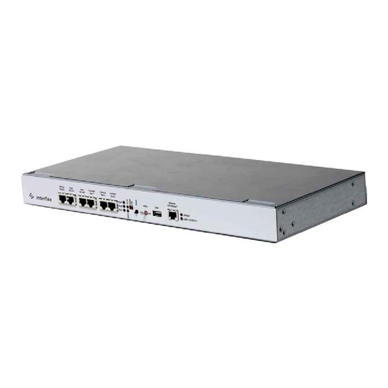
- Page 1 95-10263_Terminal Controller IF-4070 Version: 1/16/2013 Installation and Connection Instructions IF-4070 Terminal Controller...
- Page 2 Please check the goods for completeness upon receipt. Validity of the Documentation This documentation is valid for terminal controllers of the series IF-4070 with software as of version 7.12.3. It contains information on installation, connection and initial operation. For translation reasons, the annotation texts in the figures are in English.
-
Page 3: Table Of Contents
Table of Contents Function ................................4 Interfaces ................................4 Power Supply ..............................5 Sockets ................................5 LED Displays ..............................5 Reset Button ..............................5 Kaltst Switch ..............................5 SW Switch................................5 AKKU Switch ..............................5 Controller Back Side ............................6 Electronic Assembly Units: .......................... -
Page 4: Function
• to control external devices. Eight relays switch electrical devices up to 3V/ 2A, e.g. electric door openers or the inputs of alarm systems. Relay functions and switching times can be parameterized via the Interflex software • to record sensor statuses. Eight inputs record the switching actions of floating feedback sensors. The sensors can be configured as indicators or counting contacts via the Interflex software. -
Page 5: Power Supply
Power Supply Power is supplied either with 230VAC/110VAC alternating current or with a PoE-capable device IEE 802.af of power class 3 (3= up to 13 Watt). A version for low-voltage operation with 12VDC/VAC to 30VDC/VAC is optionally available. We recommend 18VDC (order number of plug-in power supply unit: 41-10063). See chapter "Connections"... -
Page 6: Controller Back Side
Controller Back Side This chapter provides information on the controller back side and the installed electronics. The mains cable with Schuko plug, the openings for inserting signal cables and cable strain reliefs with cable ties as well as the two screw nuts for fastening the cover are on the back side of the unit. L-brackets and retaining plates can be screwed to the sides for mounting into 19"... -
Page 7: Installation And Mounting
Installation and Mounting This chapter provides information on installation and mounting options. The terminal controller is designed for operation in dry rooms at temperatures from +5° C to +40°C. Mounting The housing brackets included in the delivery can be used for mounting the controller into 19” modules or screw fastening to a wall. -
Page 8: Electrical Wiring
Electrical Wiring This chapter shows the electrical wiring for connecting slave terminals, sensors and electrical devices. There is a danger of electric shock in case of faulty 230VAC installations. Severe injuries, or in worst case even death, can result. Installation of 230V systems as well as Schuko sockets may only be carried out by electricians or other qualified persons. -
Page 9: Connections
Connections This chapter shows how to connect the power supply and the data cables. All cables and cable shields must be connected as specified in order to comply with the required EMC values. Connection of the Power Supply The terminal controller with mains cable and Schuko plug is designed for operation with 230 VAC power. ... -
Page 10: Connection To Ethernet Networks
Connection to PoE Use a PoE device of power class 3 (13 Watt) for power supply. To comply with the required EMC values, the terminal controller needs a functional grounding. NOTE This connection is made via the PoE device and the patch cable. Check if there is functional grounding on the PoE device. -
Page 11: Connection Of Bus Data Cables With Slave Terminals
Connection of BUS Data Cables with Slave Terminals You can connect the data cable with slave terminals with RJ45 plugs (on the front panel) or with screw terminals (internal). The following applies for both alternatives: Three RS485 BUS interfaces are available for connection of 16 slave terminals. ... -
Page 12: Connection Of Sensors And Electric Devices
Connection of Sensors and Electric Devices You can connect the following to screw terminals KL.2 to KL.5: Up to 8 floating feedback sensors, such as e.g. reed contacts. Up to 8 electrical devices that can be switched via relay, such as e.g. electrical door openers or signal lamps up to 30V 2A. -
Page 13: Connection To Service Interfaces
Serial with RS232 and a dialog device, e.g. a PC. An RS232 connection is possible: - on the front using a self-made data cable and RJ45 connector as shown in figure 9. - on the inside with Interflex cable 75-4070-0001 and screw terminal KL.7. -
Page 14: Initial Operation
Initial Operation This chapter contains information on initial operation. Follow our procedure to ensure reliable operation. On devices with emergency power supply, open the housing and connect the accumulator cable. Carry out initial operation with all data cables and operative slave terminals connected. Procedure We recommend proceeding as follows: Switch on the power supply. -
Page 15: Point 3: Establish A Telnet Connection
Information on parameterization Please keep the following in mind during parameterization: 1. Interflex calls the software for configuration and indication of device functions "OC Task", the commands "Commands". 2. A connection to OC Task is possible: a. via the network, via TELNET or SSH connection and the factory-set IP address (see device label) or via the IP address 172.18.70.52, which can be set with the Restart push-button... -
Page 16: Point 4: Configure The Network Connections
Point 4: Configure the Network Connections Connection parameters are set with the command netpar. IP address and port number are set with the command netpar -x. DHCP is set with the command netpar -y. Point 5: Set the Parameters of the Interfaces, If Necessary Modify the Booking Memory, The interface settings and the size of the booking memory are modified with the command oc -h. -
Page 17: Point 6: Check The Connections To The Slave Terminals
Point 6: Check the Connections to the Slave Terminals The command cfg lists data from the connected slave terminals in lines 1 to 16. The following points provide information on the most important table columns. B: This column lists the BUS port number. ... -
Page 18: Setting Default Parameters
Rechargeable batteries must be disposed of in compliance with local laws and regulations. Dispose of the battery yourself or send the battery with covered, insulated poles to Interflex, 78591 Durchhausen, Grosswiesenstr. 24., with the note "Old battery to be disposed of". -
Page 19: Technical Specifications
Technical Specifications Power Supply - Mains voltage 230 VAC, +/ - 10%, 50Hz (optionally also 115VAC 60Hz) - Fuse protection 250mA, slow-blowing fuse type TR5 (48-1007) (500mA, slow-blow fuse type TR5 for devices with 110 VAC) - Power consumption approx. 16VA - Low-voltage (optional): 12 to 30VAC/VDC, recommended 18VAC/DC - PoE (Power over Ethernet)
Need help?
Do you have a question about the IF-4070 and is the answer not in the manual?
Questions and answers