
Subscribe to Our Youtube Channel
Related Manuals for MRC PTX-PRO

Summary of Contents for MRC PTX-PRO
- Page 1 PTX-PRO 13 GHz Transmitter User and Technical Manual Manual Part No. 400590-1 Rev. B June 2009...
-
Page 3: About This Manual
Part number 400590-1 The information and design contained within this manual was Revision B June 2009 originated by and is the property of MRC. MRC reserves all PTX-PRO 13 GHz Transmitter (PTX-PRO) patent proprietary design, manufacturing, reproduction use, and sales rights thereto, and to any articles disclosed therein, except Copyright to the extent rights are expressly granted to others. - Page 4 EIRP = P * (10 ^ (G / 10)) = (antilog of G/10) * P RF Exposure - Safe Working Distances MRC provides this warning for safety purposes with the intent to P = RF power delivered to the antenna in mW inform the user of the potential hazard of RF exposure.
- Page 5 20.07 modulation 31.49 MRC, in accordance with the requirements set forth by the 176.73 FCC, provides this information as a guide to the user. It is assumed that the users of this equipment are licensed and...
- Page 6 (WEEE) - The product must not be disposed of with other waste at the end of its life cycle. It is the user’s responsibility to dispose of the waste equipment by handing it over to a designated collection point for recycling. PTX-PRO User and Technical Manual Notices Notices-iv...
-
Page 7: Table Of Contents
Tell Us What You Think! - - - - - - - - - - - - - - - - - - - - - - 1-2 PTX-PRO - - - - - - - - - - - - - - - - - - - - - - - - - - - - - - 5-1... - Page 8 Theory of Operation - - - - - - - - - - - - - - - - - - - - 8-1 PTX-PRO Programming - - - - - - - - - - - - - - - - - - - 6-12...
-
Page 9: Introduction
Related Documents Calling for Service • Van Portable Systems User and Technical Manual MRC Technical Support is available 24 hours a day, 7 days a (part no. 400522-1) week. During regular business hours you can reach our expert staff directly. -
Page 10: Tell Us What You Think
Model number and serial number of the unit. This is located on a label on the bottom of each unit. • Approximate purchase date. • Firmware version, which appears on the PTX-PRO alphanumeric display at startup. - OR - • Firmware version(s) displayed on the Main page of the MRC Radio Configurator (Configurator), when the Configurator software is connected to the PTX-PRO. -
Page 11: Product Description
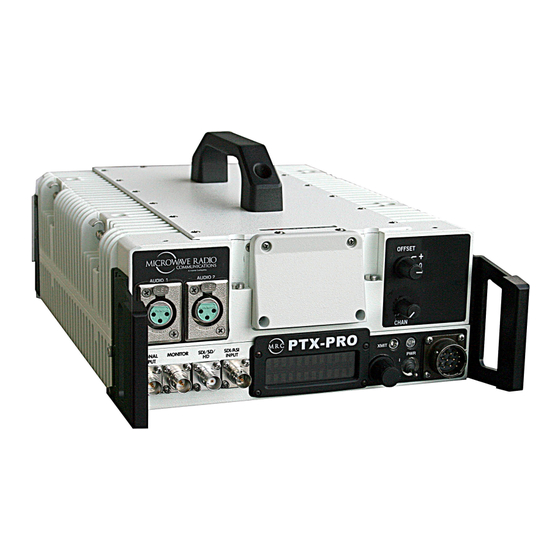
Product Description microwave signal outputs for communications purposes. Figure 2-1: PTX-PRO Transmitter - Typical Chapter Overview This chapter provides an overall description of the PTX-PRO 13 GHz Transmitter (PTX-PRO) components, options, and capabilities. Here are the topics covered: Topic Page... -
Page 12: Power Options
Power Options Portable Deployment In portable applications, the PTX-PRO is The architecture of the PTX-PRO allows a number of options for typically mounted on an MRC Quick Release Mount for easy the external power source. The PTX-PRO configurations attachment to an MRC tripod. The Quick Release Mount... -
Page 13: System Integration
For the field operator, the PTX-PRO has up to nine Presets that can be selected from the front panel. Each Preset controls key parameters such as modulation, frequency, and audio and video settings. - Page 14 PTX-PRO User and Technical Manual Product Description...
-
Page 15: Routine Operation
Control Switch Front Panel vs. Configurator Settings 3-14 XMIT LED For a summary of settings that can be made with the PTX-PRO PWR Switch front panel control switches and which settings are made using AC/DC Power Connector the Configurator software, see Section 3.7 on page... -
Page 16: Front Panel Controls, Indicators, And Connectors
Controls, indicators, monitor system status and to control system settings. and connectors contained on the PTX-PRO front panel are shown in Figure 3-1. - Page 17 Monitor options. Shut down the PTX-PRO and disconnect power. Monitor options are dependent upon the Preset operating mode selected and provide current status of the PTX-PRO. Status includes, but is not limited to, the following: LED Color Meaning • Frequency Setting ----- Power is not on in the unit.
-
Page 18: Rear Panel Connectors And Fuses
Connector PWR Switch The front panel PWR (power) switch controls application of AC or DC power to the PTX-PRO. RF Output Type “N” Connector The rear panel 50 ohm, type “N”, female connector provides the RF output to the transmitting... -
Page 19: Preparing For Operation
Some typical screens are shown in Figure 3-3. Exact typically be mounted on an MRC Quick Release Mount for easy screens displayed will vary. attachment to an MRC tripod. Other mounts are also available. The PTX-PRO will typically power up using the last For additional information, refer to the “Installation”... -
Page 20: Using The Display Screens
Preset • LMS-T (Terrestrial) (LMS-T mode) Output Power Once the PTX-PRO is set up and powered up, you will be able to Level check its configuration and monitor its operation. When configuration settings are established for the individual Presets using the Configurator software, the individual Preset operating Accessing the Main Screen You can access the Main screen modes should be recorded for quick reference. -
Page 21: Using The Monitor Screens In Cofdm Mode
3.5.3 Using the Monitor Screens in Ext IF Input Mode When the PTX-PRO is operating in the Ext. IF In mode, the 70 MHz IF input signal to the SIGNAL INPUT connector is routed through the transmitter. See Figure 3-7 on page 3-10 for the Ext. - Page 22 Displays will alternately Normal appear if no video is present. MPEG AudioA NOTE All Monitor Screens AESEBU Streo revert to the Main Screen after 7 seconds of inactivity. MPEG AudioB AESEBU Streo Error Page PTX-PRO User and Technical Manual Routine Operation...
- Page 23 ASI/SDI In appear. QPSK 8MHz COQPSK 8MHz Displays power level ASI: FE1/2 GI1/8 and Channel number. NOTE All Monitor Screens IF CW revert to the Main Screen after 7 seconds of inactivity. Error Page PTX-PRO User and Technical Manual Routine Operation...
- Page 24 Main Screen 0.0dB NOTE All Monitor Screens revert to the Main Screen Preset Band after 7 seconds of 13 GHz inactivity. Displays power level Mode and Channel number. Ext IF Input Error Page PTX-PRO User and Technical Manual Routine Operation 3-10...
- Page 25 Displays will alternately Normal appear if no video is present. MPEG AudioA NOTE All Monitor Screens AESEBU Streo revert to the Main Screen after 7 seconds of inactivity. MPEG AudioB AESEBU Streo Error Page PTX-PRO User and Technical Manual Routine Operation 3-11...
-
Page 26: Ptx-Pro Control Operations
PTX-PRO Control Operations This section describes how to configure your PTX-PRO using the front panel control switch. Turning the front panel control switch counterclockwise (ccw) controls transmitter functions including changing Presets, changing the video input (VI) mode, changing SD or HD video inputs, changing color bar settings, and setting RF attenuation levels. - Page 27 1) PRESS to activate operating mode is COFDM The HD option may only be selected if 2) TURN to change or LMS-T. your PTX-PRO contains the licensed, 3) PRESS to select SD Mode only Select SD or HD factory-enabled HD option. If the...
-
Page 28: Front Panel Vs. Configurator Settings
Front Panel vs. Configurator Table 3-1: Front Panel vs. Configuration Setting (Continued) Settings Available Using Set Using The design of the PTX-PRO and the Configurator software Parameter Settings Control Configurator makes commonly available settings accessible from the PTX- Switches PRO front panel switches and alphanumeric display and more ✔... - Page 29 • Standard Audio A Input • Test Tone ✔ ✔ • • Analog ✔ ✔ Chroma • 4:2:0 • SDI EMB Format ✔ ✔ • 4:2:2 (Special • AES EBU license required) PTX-PRO User and Technical Manual Routine Operation 3-15...
- Page 30 Interval ✔ • COFDM (Special licenses required) ✔ Modulation • QSPK ✔ • 16 QAM ✔ • 64 QAM ✔ Bandwidth • 6 MHz ✔ • 7 MHz ✔ • 8 MHz PTX-PRO User and Technical Manual Routine Operation 3-16...
-
Page 31: Troubleshooting
The Support. internal processors are not running. Power LED Above the PTX-PRO front panel PWR switch is a multi-color PWR LED that provides unit status indications. The PWR LED status indications are listed in Table 4-1. PTX-PRO User and Technical Manual... -
Page 32: Display Messages
One of the ways the PTX-PRO will alert you to problems is by error messages on the PTX-PRO front panel displays. These are displayed on the Monitor screens. -
Page 33: Error Codes
Error Codes 4.4.1 Error Status The significance of the Error Status digit depends on what The PTX-PRO has a library of diagnostic error codes to help you Primary Error Code is being reported. See Table 4-3. pinpoint any problems. These error codes: Table 4-3: Error Status Digit •... - Page 34 • Contact technical staff. E080 Communication Failure with • Verify condition of cable If problem persists, possible hardware failure. Call MRC the COFDM/MPEG Module connections. Contact technical staff. Technical Support. Parameter Errors (Some internal parameter is outside of allowable limits.) E030 TX 2.048 Volt Reference...
- Page 35 Code E034 TX Temperature Error • Check PTX-PRO to be sure it is not If errors persist with proper location and airflow and too close to sources of heat. correct power is connected, unit has suffered internal Relocate PTX-PRO, if possible.
-
Page 36: Operational Problems
If frequency offsets are used, verify offsets are identical between Transmitter and Receiver. • Contact technical staff. Video source configuration • Verify PTX-PRO front panel settings match • Verify video inputs match problem video source inputs. Configurator software settings. •... -
Page 37: Configurator Troubleshooting
• Verify power source is turned • Call MRC Technical Support. • Contact technical staff. PWR LED on PTX- PTX-PRO is indicating a Minor • Check all Monitor Screens on • Error messages: Troubleshoot per PRO is amber. Alarm. PTX-PRO display. -
Page 38: Configurator Operational Problems
Requirements. RS-232 cable is Replace cable. defective. CD damaged. Contact MRC Technical Support. Installed PTX-PRO Contact MRC hardware is Technical Support. Problem with PC or Contact your PC service defective. its disk drive. provider. PTX-PRO User and Technical Manual Troubleshooting... - Page 39 Programs” function in trying to run. Microsoft Windows Control Panel to AND / OR uninstall the Configurator, then Get “Runtime reinstall it. Error” message. Problem with PC or Contact your PC service its disk drive. provider. PTX-PRO User and Technical Manual Troubleshooting...
- Page 40 PTX-PRO User and Technical Manual Troubleshooting 4-10...
-
Page 41: Advanced Operation
Configurator Settings” on page 3-14. The procedures described in this chapter assume you already Here are the topics covered: know how to operate your PTX-PRO. If this is not the case, please review the following Chapters in this manual: Topic Page “Introduction”... -
Page 42: System Rules
New configurations can created from scratch, updated from existing files on your PC, or may be loaded in from a PTX-PRO • Configuration settings may be loaded into the Configurator and modified. -
Page 43: Channel Plans
PC desktop. New channel plans can be created from scratch, updated from existing files on your PC, or may be loaded in from a PTX-PRO The settings are grouped into pages according to function. The and modified. Once a channel plan is created or modified and pages are accessed using tabs. - Page 44 Close Licensed Configurator Features window Radio Control Record licensed options highlighted in COM Port menu Connect green Radio Mode, Select COM port MPEG, COFDM, required LMS-T, Channel Plan, and Licensing Tabs are displayed PTX-PRO User and Technical Manual Advanced Operation...
-
Page 45: Create New Configuration On-Line
LMS-T, Channel Note Plan, and If the Remember Last PA State option Licensing tabs is selected, the PTX-PRO will return to Change Preset are displayed the last state it was in when it was Names Menu powered down. If the radio was in standby, it will return to standby upon power up;... - Page 46 SDI 625 In, PAL 15.0; if Chroma required (Active In, PAL M In, or setting is 4:2:2, in HD mode only) PAL N In (Radio valid range is Type PAL) 2.0 – 50.0 PTX-PRO User and Technical Manual Advanced Operation...
- Page 47 (Range is 32 - (Range is 32 - (Range is 32 - If check box is active on some 8190) 8190) 8190) 8190) 8190) not selected, PID radio data must be configurations) entered manually PTX-PRO User and Technical Manual Advanced Operation...
- Page 48 1/16, or 1/32, as MHz, or 8 MHz, 3/4, 5/6, or 7/8, 20 MHz, as 16 QAM, as available option 1/16, as required QPSK, as as required as required required required required required PTX-PRO User and Technical Manual Advanced Operation...
- Page 49 Program All Save All Settings Band (13 GHz) Settings to Radio to File Preset Save configuration Configuration settings are File window is loaded into the displayed radio. Save file PTX-PRO User and Technical Manual Advanced Operation...
-
Page 50: Load And Modify Configuration Settings On- Line
All Preset settings Active Preset Load Preset and channel plans Menu Enter Preset are loaded into the Names (12 Configurator characters Only the selected Select Preset max) Preset is loaded required into the Configurator PTX-PRO User and Technical Manual Advanced Operation 5-10... - Page 51 4:2:0, valid characters Max) characters required for HD (Active in HD range is 1.5 – Max) mode) mode only) 15.0; if Chroma setting is 4:2:2, valid range is 2.0 – 50.0 PTX-PRO User and Technical Manual Advanced Operation 5-11...
- Page 52 (Range required (Range If check box is active on some 8190) 8190) 8190) is 32 - 8190) is 32 - 8190) not selected, PID radio data must be configurations entered manually PTX-PRO User and Technical Manual Advanced Operation 5-12...
- Page 53 Guard interval Modulation Bandwidth available option Guard interval option, as correction (FEC), Type option, as option, as Type option, as option, as option, as required as required required required required required required PTX-PRO User and Technical Manual Advanced Operation 5-13...
- Page 54 Preset settings that were changed, are programmed into the radio. Configuration settings for only When Program Preset is selected, only the selected the selected Preset is programmed into the radio. Preset are programmed into radio PTX-PRO User and Technical Manual Advanced Operation 5-14...
-
Page 55: Load Configuration File Into Radio On-Line
5.3.5 Load Configuration File into Radio On-Line The flowchart required to load a configuration and channel plan from a file on your PC into your PTX-PRO is contained in Figure 5-12. Figure 5-12: Load Configuration file into Radio On-Line MRC Configurator Icon... -
Page 56: Change Preset Names In On-Line Mode
Names Menu radio Saves configuration file to a PC Enter Preset Names (12 characters Max) Preset Names and all configuration settings are saved to a file on a PC PTX-PRO User and Technical Manual Advanced Operation 5-16... -
Page 57: Create Channel Plan Offline
22, as required Radio Mode, Select PTX-PRO Select 13 GHz Select <Low MPEG, COFDM, Dual Band Band Disabled> (12.7 – 13.25) Save file LMS-T, FMT, option option Channel Plan, and Licensing tabs appear PTX-PRO User and Technical Manual Advanced Operation 5-17... -
Page 58: Modify Channel Plan In Offline Mode
Low Band Pull- High Band Pull- frequencies are displayed for all Down Menu Down Menu channels and bands, as required Select <Low Select 13 GHz (12.7 – 13.25) Band Disabled> option option PTX-PRO User and Technical Manual Advanced Operation 5-18... -
Page 59: Load And Modify A Channel Plan On-Line
Program All Bands to Radio is selected, only channel plan settings are programmed into the radio. No Preset settings are programmed into the radio. Save file PTX-PRO User and Technical Manual Advanced Operation 5-19... -
Page 60: Load Channel Plan File Into Radio On-Line
5.3.10 Load Channel Plan File into Radio On-Line The flowchart required to load a channel plan from a file on your PC into your PTX-PRO in the on-line mode is contained in Figure 5-17. Figure 5-17: Load Channel Plan into Radio in On-Line Mode... -
Page 61: Add Licensed Option
5.3.11 Add Licensed Option The flowchart required to add new licensed options to your PTX-PRO is contained in Figure 5-18. The license required to add a new licensed feature must be obtained from MRC prior to performing this procedure. Figure 5-18: Add Licensed Option... - Page 62 PTX-PRO User and Technical Manual Advanced Operation 5-22...
-
Page 63: Installation
Chapter Overview • DO NOT discard the container or packing material until This chapter describes how to unpack and install your PTX-PRO you have inspected the equipment and are sure there is 13 GHz Transmitter (PTX-PRO). The topics covered in this no shipping damage. -
Page 64: Mounting And Cabling
Mounting and Cabling of the PTX-PRO using four 1/2-inch long, #6-32, flat head screws. The Quick Release Mount typically remains attached to the PTX-PRO. The Quick Release Mount and PTX-PRO are then attached to the Dovetail Adapter Plate machined into the... - Page 65 Mounting - Non-MRC Tripod (Option 1) To mount a PTX-PRO Tripod on a non-MRC tripod, one option is to attach the Quick Release Mount Mount to the bottom of the PTX-PRO using four 1/2-inch long, #6-32, flat head screws.
- Page 66 PTX-PRO. See Figure 6-5 on page 6-5. Adapter is attached to the bottom of the PTX-PRO using four 1/2-inch long, #6-32, pan head screws, lock washers, and flat washers. The Quick Change Adapter and PTX-PRO assembly is then attached to the QuickSet tripod mount and is secured with the tripod mount locking clamp.
-
Page 67: Power Connections
DC power source for your PTX- PRO, do not exceed 36 volts DC input power. Antenna (2 Options Power is distributed to the PTX-PRO through the front panel Shown) PWR connector on the PTX-PRO. Quick Release Mount... -
Page 68: Power Cable Assemblies
12-Pin, Male, Panel-Mount 90 to 264 VAC DC Power Cable Assembly A prefabricated DC Power Cable Assembly is available from MRC to connect the PTX-PRO PWR Neutral connector to a DC power source. The DC Power Cable Assembly is 10 ft. (3 m) long. The DC Power Cable Assembly comes with a power connector on one end only. -
Page 69: Additional Powering Notes
Do not run cords where they can be walked upon. Protect cables against pinching and chafing. Pay special attention to locations where the cables enter or exit an enclosure or make a sharp bend. PTX-PRO User and Technical Manual Installation... -
Page 70: Grounding
(See Figure 6-10 on page 6-10) is available that splits the audio connections into two separate All PTX-PRO audio inputs are applied to either the front or rear cables with XLR connectors. The two connectors are labelled panel audio connectors. -
Page 71: Rear Panel Audio Connections
6.8.2 Rear Panel Audio Connections The PTX-PRO provides a maximum of four audio circuits. Each audio circuit is a 3-wire balanced circuit capable of carrying one The rear panel AUDIO 3 & 4 10-pin female connector receives tone or voice signal. An audio circuit can carry one analog balanced audio inputs for audio channels 3 and 4. -
Page 72: Aes/Ebu Audio Input
In digital mode, the audio channels are referred to as Audio A and Audio B. In digital mode, the PTX-PRO receives a digital signal and routes the data to the MPEG encoder and then to the COFDM 6.8.5 Video Connections modulator. -
Page 73: Signal Connections
Radio programming using a PC • Wayside data communication. The PTX-PRO can be connected to a PC via a standard null modem cable or it can be interfaced to a LAN for applications such as remote monitoring and control. PTX-PRO User and Technical Manual... -
Page 74: Ptx-Pro Programming
Compatibility MRC has verified that the Wayside channel is Microsoft Windows-based PC. compatible with the following receivers: The PTX-PRO is configured to be a DTE device. If you need to • STRATA Receiver Unit (RXU) with MPEG decoding access the radio programming connections, a null modem cable •... -
Page 75: Panel Data Connectors
Data connections on the Receive end of the Wayside channel for PC or laptop PC. When connected to a DTE device, a null the RS 232 serial port connector on the PTX-PRO are shown in modem cable must be connected between the DTE device and Figure 6-17 on page 6-16. -
Page 76: Networking
This allows both monitoring and programming the PTX-PRO from a remote location. Figure 6-15: Lantronix UDS-10 Device Server To connect the PTX-PRO to a network, you will need the items described below. See Figure 6-14. - Page 77 To PTX-PRO RS-232 Connector DB-9 (Male) Receive Data Radio Transmit Data Data Signal Ground Wayside Data to External Device Wayside Transmit Wayside Data Data Receive Wayside Data Wayside Data from External Device (Not Used) PTX-PRO User and Technical Manual Installation 6-15...
-
Page 78: Powering Up
When the wiring and mounting are completed, it is time to power CAUTION Be sure the power being supplied matches up the PTX-PRO. As good practice, you should make a final the power required by the equipment. check before power is applied. -
Page 79: Configurator Software Installation
Processor Speed 400 MHz 1 GHz 96 MB 256 MB If the PTX-PRO does not power up normally, refer to “Troubleshooting” Chapter on page 4-1. Screen Resolution 800x600 1024x768 Figure 6-18: Typical PTX-PRO Power Up Screen •... - Page 80 Use the “Add/Remove Programs” feature in the Microsoft Windows Control Panel to do this. Locate the CD that was provided with your PTX-PRO. Insert the CD into your computer CD drive. Using the My Computer icon on your PC (or any other method), navigate to that CD drive and display the CD directory on your screen.
- Page 81 Select the Next option button and observe the Installing MRC Radio Configurator window is displayed. See Figure 6-22. Select the Close option button and observe the MRC Figure 6-22: Installing MRC Radio Configurator Window Radio Configurator icon is displayed on your desktop. See Figure 6-24.
-
Page 82: Product Modifications
The product you purchased has been carefully designed and tested, and is warranted to meet specifications when connected and operated as described in this manual. Note If you modify a product without authorization from MRC, you will void the warranty. PTX-PRO User and Technical Manual Installation 6-20... -
Page 83: Replacement Parts
See ”Data Connections” on page 6-11. Since there are no supported field repairs on the PTX-PRO. Audio Input Connector Connects to PTX-PRO AUDIO 3 & 4 The only parts available are external cables and mounting connector for Audio 3 and 4 inputs. -
Page 84: Power Fuses
+11.0 to +36.0 VDC sealing the PTX-PRO enclosure after repair requires exacting techniques and special fixtures to ensure weather resistance of Power fuses for the AC and DC configurations of the PTX-PRO the units. are located on the rear panel of the unit. -
Page 85: Theory Of Operation
PTX-PRO is shown in Figure 8-1. • MPEG encoding with SD and optional HD video solution The PTX-PRO is a versatile portable transmitter designed to technologies accept an IF 70 MHz input signal or composite video signal, • Front panel local control audio signals, or SD/HD SDI signals or ASI/SDI signals from •... -
Page 86: System Theory Of Operation
The PTX-PRO command and control power supply modules technologies. contain external and internal communications circuitry, as well as The PTX-PRO can accept a wide variety of signal formats and supplying necessary system voltages. includes an RF up-converter for use in transporting signals over The PTX-PRO power supply accepts a wide range of DC input a microwave link. - Page 87 Figure 8-2: Standalone 13 GHz PTX-PRO Block Diagram 13 GHz Band Pass RF Output 13 GHz Mixer 13 GHz Filter Power Amplifier Up Converter 70 MHz SDI/SD/ SDI/ASI INPUT AUDIO 1 SIGNAL HD Encoder/ INPUT Modulator AUDIO 2 Baseband Combiner AUDIO 3 &...
- Page 88 PTX-PRO User and Technical Manual Theory of Operation...
- Page 89 Index load configuration file into the PTX-PRO ..5-3 system rules ....... 5-2 Conventions .
- Page 90 Proprietary Material ......Notices-i MRC Customer Service ......1-1 PTX-PRO Business Hours .
- Page 91 Power cable assemblies ....6-6 PTX-PRO ........7-1 power requirements .
- Page 92 WEEE ........Notices-iv PTX-PRO User and Technical Manual...
Need help?
Do you have a question about the PTX-PRO and is the answer not in the manual?
Questions and answers